
Abstract
A single-structured hybrid gas-magnetic bearing (HGMB) has been proposed for frequent start/stop occasions, which eliminates foil structures or static pressure systems by using the closed magnetic poles of the active magnetic bearing (AMB) as the bushing of the gas bearing. This allows the proposed bearing to realize the functions of both AMB and gas bearing with a single bearing structure. In this paper, the bias currents of AMB, aimed for enhanced load capacity and dynamic characteristics, are omitted to reduce power consumption and heat. The combination of zero-bias AMB and rigid self-acting gas bearing in a single bearing structure is therefore proposed. The rotor orbits of gas bearing, AMB, single-structured HGMB, and single-structured zero-bias HGMB in conditions of varied horizontal and vertical external loads are simulated. The dynamic performances during the run-up processes of AMB, HGMB, and zero-bias HGMB are investigated. The electromagnetic forces of each kind of bearing are compared. Numerical results demonstrate that by applying the single-structured zero-bias HGMB, the power consumption can be significantly reduced in contrast with pure AMB and single-structured HGMB. The reduced load capacity and dynamic characteristics of zero-bias AMB can be compensated by the rigid self-acting gas bearing, making the single-structured zero-bias HGMB an ideal candidate for cryogenic, ultra-high speed as well as frequent start/stop occasions.
Keywords
Introduction
In industrial applications, there is an increasing need for machinery that rotates at ultra-high speeds [1]. Contactless bearing concepts like magnetic bearings or gas bearings are promising bearing technologies for high rotating speeds. To reach higher rotating accuracy, AMBs and gas bearings are combined to enhance the bearing performance [2,3].
A nested arrangement for the hybrid foil-magnetic bearing (HFMB) was developed by Heshmat et al. [4], in which the gas foil bearing (GFB) was assembled into the space between the AMB and the journal. The nested configuration decreases shaft length and leads to less bearing load, making it a common bearing arrangement [5–7]. In regard to theoretical research, a coupled dynamic model combining the dynamics of electromagnetic actuator and GFB was established by Basumatary et al. [8]. Numerical results indicated that sub-synchronous vibrations of GFB are decreased and bearing stability is improved with the electromagnetic actuator. Due to the inherent instability of AMBs, a controller is indispensable to adjust the journal motion based on its displacement feedback [9]. Relevant numerical simulations applying the proportional-integral-derivative (PID) control algorithm were studied by Heshmat et al. [10] and Tian et al. [11]. Pham and Ahn [12] investigated the optimal control gains and offsets of the AMBs. Experimental results showed that the optimized control gain reduces journal vibration amplitude by 26% at the bending critical speed, and saves energy consumption of the driving motor by 50% during the run-up test. Jeong et al. [13] experimentally verified that control stiffness plays a dominant role on rotor vibration and it could be optimized.
In cryogenic environment, it is curial to cut down power consumption and heat generation, especially for ultrahigh-speed occasions. Zero-bias AMB is a kind of bearing which eliminates the bias current/flux to reduce harmful overheating, useless eddy current losses, hysteresis losses and Ohmic losses induced by the bias current/flux [14]. Liu et al. [15] analyzed the functional relationship between control current, rotor displacement, and the speed term based on an average current assumption. A linear control algorithm was therefore designed and verified on both horizontal and vertical axial AMB test-rigs. The results demonstrate good control performances in condition of external disturbances. Zero-bias AMBs are suitable for light-load situations despite having a reduced load capacity and stiffness. The disadvantages of the zero-bias AMB can be mitigated when combined with gas bearing.
Liu et al. [16] proposed a single-structured HGMB, which integrates the bearing characteristics of gas bearing and AMB with only single bearing structure, thus eliminating foil structures or externally pressurization and reducing manufacturing difficulty. Based on the proposed single-structured HGMB, we employed zero-bias AMB to further reduce power consumptions and heat. In this study, the rotordynamic performances of the single-structured zero-bias HGMB-rotor system under varied external loads are investigated. The electromagnetic forces of zero-bias HGMB are compared with that of pure gas bearing, pure AMB and HGMB. The dynamic performances and electromagnetic forces during the run-up processes of pure AMB, HGMB, and zero-bias HGMB are also investigated. The appropriate applications for zero-bias HGMB are analyzed.
Single-structured HGMB-rotor system
Schematic of single-structured HGMB
The single-structured HGMB utilizes the hardware of the AMB to realize the functions of both AMB and gas bearing. Figure 1 depicts the schematic of the single-structured HGMB. The closed magnetic pole of the AMB, which is comprised of magnetic and non-magnetic materials, also acts as the bushing of the rigid self-acting gas bearing. As for conventional HGMB [4], the foil structures of the GFB are inserted into the non-magnetic material (e.g., epoxy molding), which is located around the magnetic poles. The advantage of single-structured HGMB is that foil structures of the GFB are eliminated, leading to a more compact design and more efficient AMB [16].
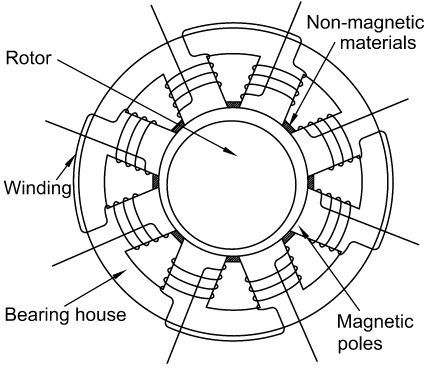
Schematics of the single-structured HGMB.
The illustration of the single-structured HGMB-rotor system is demonstrated in Fig. 2.
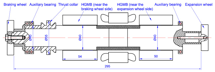
Schematic of the single-structured HGMB-rotor system.
The HGMB-rotor system consists of two HGMBs, thrust collar, braking wheel, and expansion wheel. The rotating shaft is composed of steel, with density 7850 kg/m3, Young’s modulus 2 × 10¹¹ Pa, shear modulus 7.69 × 10¹⁰ Pa, and Poisson’s ratio 0.3. The braking wheel and the expansion wheel are comprised of aluminum alloy, with density 2710 kg/m3, Young’s modulus 6.90 × 10¹⁰ Pa, shear modulus 2.65 × 10¹⁰ Pa, and Poisson’s ratio 0.33. The gravitational acceleration is 9.8 m/s2, which is along the radial direction of the rotor.
The rotor system is supported by two single-structured HGMBs. The width of the HGMB near the braking wheel side is 5.4 × 10⁻² m and that of the HGMB near the expansion wheel is 5.0 × 10⁻² m. Table 1 presents details of structural and operational parameters of the single-structured HGMB-rotor system. The rotor unbalance is distributed on the left and the right ends of the rotor. The unbalance on the braking wheel is 2.05 × 10⁻⁶ kg, and that on the expansion wheel is 2.70 × 10⁻⁶ kg. The unbalance phase angles of both ends measured from horizontal line are 0.
Parameters of the single-structured HGMB-rotor system
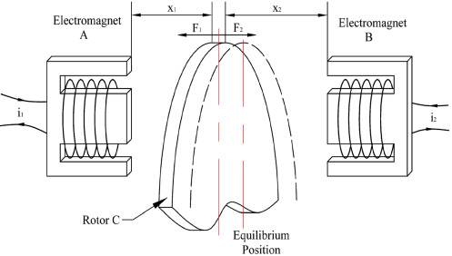
Simplified model of the 1-DOF zero-bias AMB [15].
Zero-bias AMB characteristics
Zero-bias AMB is a kind of bearing which eliminates the bias current/flux to reduce power consumption and rotor heating. As shown in Fig. 3, the simplified 1-DOF zero-bias AMB model consists of two identical electromagnets (EMs), generating attractive forces (F
1 or F
2) on the rotor. When the rotor approaches one of the EMs, the switching power amplifier of the EM with shrinking air gap turns off while that of the other EM switches on to adjust rotor motion (Fig. 4). In the zero-bias AMB system, the magnetic forces of the EMs are described as [17]
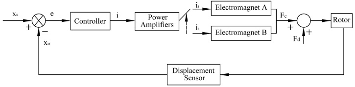
Block diagram of zero-bias current AMBs [15].
The magnetic suspension force in X and Y direction can be written as
The displacement stiffness k
j
and the current stiffness k
ij
can be calculated through the first order partial derivative of the magnetic force
Static analysis
Assuming that the flow process is isothermal and the air is an ideal gas, the governing equation for hydrodynamic pressure with the compressible gas flow in a self-acting gas bearing is given by the Reynolds equation [18]
The dimensionless gas film thickness can be written as:
The gas film between the gas bearing and the journal can be compared to a spring and a damper to carry load and reduce vibrations. The dynamic characteristic coefficients (i.e., dynamic stiffness and dynamic damping) of the gas bearing vary with the working conditions and affect the rotordynamic behaviors. The dynamic characteristic coefficients can be derived from the dynamic Reynolds equation:
Assume that the rotor equilibrium position at the operating speed w is (x
0, y
0). The rotor is subjected to a small perturbation at the equilibrium position and then shifts to point O
j
. The small perturbation can be denoted as a small displacement (Δx, Δy) and a small velocity
The idea of FEM is to divide the rotor into microelements. Then mass, damping, and stiffness matrices of these elements are figured out based on the work-energy theory. After that, the matrices of all microelements are assembled to obtain mass matrix [M], damping matrix [C], stiffness matrix [K], and force vector [Q] of the entire rotor. Finally, critical speed and dynamic response of the rotor can be obtained by solving the dynamic equation with Newmark-𝛽 method.
Element equation
The HGMB-rotor system consists of rigid disk, shaft segment, and bearing, etc. The motion equation of each component is listed as follows.
(1)
Assume that the mass, the diameter moment of inertia and the polar moment of inertia through the rotating axis of a rigid disk are m, J
d
, and J
p
. The displacement vectors of the rigid disk are
(2)
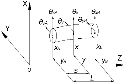
The motion of an elastic shaft element, as shown in Fig. 5, is described by eight end-point displacements including two translational displacements in the X and Y directions and two rotational displacements about the X and Y axes at end point A and B. The shaft element is assumed to be isotropic and symmetric about the axis of rotation (Z). Typically, the end-point displacements are arranged in the following form:
Timoshenko beam shaft element.
For shaft element i, suppose that:
Assuming that the HGMB-rotor system has N nodes connected by (N − 1) discrete elements, the displacement vectors of the system are listed as follows [20]
By combing the motion equations of the rigid disk and the elastic shaft element (i.e., Eq. (13) and (16)), the rotor-disk system’s dynamic equation is represented by:
The HGMBs are modeled as discrete elements with integrated stiffness and damping of the magnetic bearing and the gas bearing. The support forces from the AMB and the gas bearing are related to bearing stiffness and damping, therefore can be moved to the left side of Eq. (22). After incorporating the HGMB supporting forces, Eq. (22) can be revised as follows:
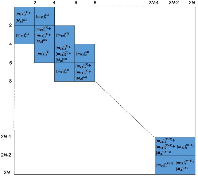
The entire assembled mass matrix of the HGMB-rotor system.
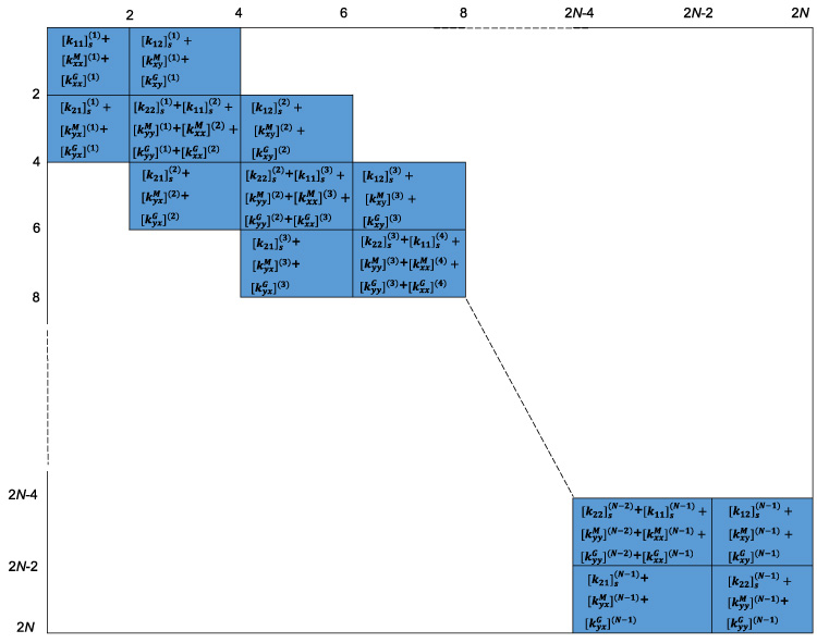
The entire assembled stiffness matrix of the HGMB-rotor system.
Equation ((23)) can also be expressed as follows when the displacement vectors are reorganized [21]:
The force vector
Transient analysis for constant rotating speed is performed to ascertain the steady-state response. The startup, shutdown, or rotor drop in failure conditions, however, are also significant. In these cases, the motion equations of the HGMB-rotor system are concerned with the varying rotating speed:
Station numbers of the HGMB-rotor system are shown in Fig. 8. The HGMB near the braking wheel side is at station 9 and the HGMB near the expansion wheel is at station 12. The mass unbalance is distributed on the left end (station 1) and the right end (station 16) of the rotor.
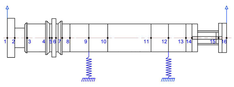
Schematic of the HGMB-rotor system and station numbers.
To explore the dynamic characteristics of the zero-bias HGMB, rotor orbits and power consumptions of different types of bearings (self-acting gas bearing, AMB, HGMB, and zero-bias HGMB) under horizontal and vertical external loads are analyzed. The parameters of the HGMB are shown in Table 1, which are also applicable to the gas bearing, the AMB, and the zero-bias HGMB. The horizontal external loads range from 0 N to 30 N and the vertical external loads vary from 0 N to −30 N with an increment of 10 N. Both the horizontal and the vertical external loads are step forces.
Dynamic stiffness and damping of the self-acting gas bearing are calculated by Eq. (12). Bearing stiffness and damping varied from case to case due to distinct external loads, and are listed in Table 2.
Stiffness and damping of the gas bearing under varied external loads
*F x denotes horizontal external loads and F y denotes vertical external loads.
Dynamic stiffness and damping of the HGMB are integrated by self-acting gas bearing and AMB. Similarly, dynamic stiffness and damping of the zero-bias HGMB are the sum of that of self-acting gas bearing and zero-bias AMB.
Due to the inherent instability of zero-bias AMB, a controller is essential to adjust the rotor motion in response to rotor feedback. Since the GFB must operate at a specific eccentricity in order to carry load, the eccentric location—also applied as the control reference—must be initially determined for the PID controller.
A proportional-derivative (PD) controller is considered for HGMB in the reported work [13]. The PD control is concerned with proportional gain k P and differential gain k D . Based on Eqs (5) and (6), control stiffness of AMB is strongly related to the proportional gain k P , and the damping is affected by the differential gain k D .
It is critical to determine the zero-bias HGMB control variables since they have a significant impact on the dynamic properties of the rotor bearing system. As can be seen in Fig. 9, as the proportional gain increases from 2.3 × 10⁴ to 4.8 × 10⁵, the journal orbits of the zero-bias AMB near the braking wheel side at 92 krpm decrease significantly. This is due to the increased control stiffness. Figure 10 shows the magnetic forces of the zero-bias AMB with varied proportional gains. It was found that the average magnetic force rises tremendously when k P increases to 6.8 × 10⁴.
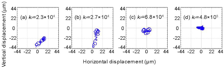
Journal orbits at 92 krpm of zero-bias AMB under varied control parameters: (a) k P = 2.3 × 10⁴; (b) k P = 2.7 × 10⁴; (c) k P = 6.8 × 10⁴; (d) k P = 4.8 × 10⁵.
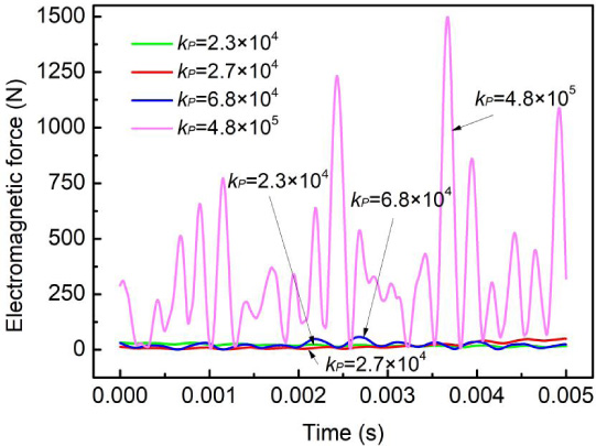
Electromagnetic forces of zero-bias HGMB at 92 krpm under varied control parameters: (a) k P = 2.3 × 10⁴; (b) k P = 2.7 × 10⁴; (c) k P = 6.8 × 10⁴; (d) k P = 4.8 × 10⁵.
Based on the vibration performance and the power consumption analysis, the optimal proportional gain is chosen as 6.8 × 10⁴. Control damping can also be applied to suppress the vibration, but the control stiffness has a dominant effect on the rotor-bearing system. Hence, the damping value is chosen as 7 according to the simulation results.
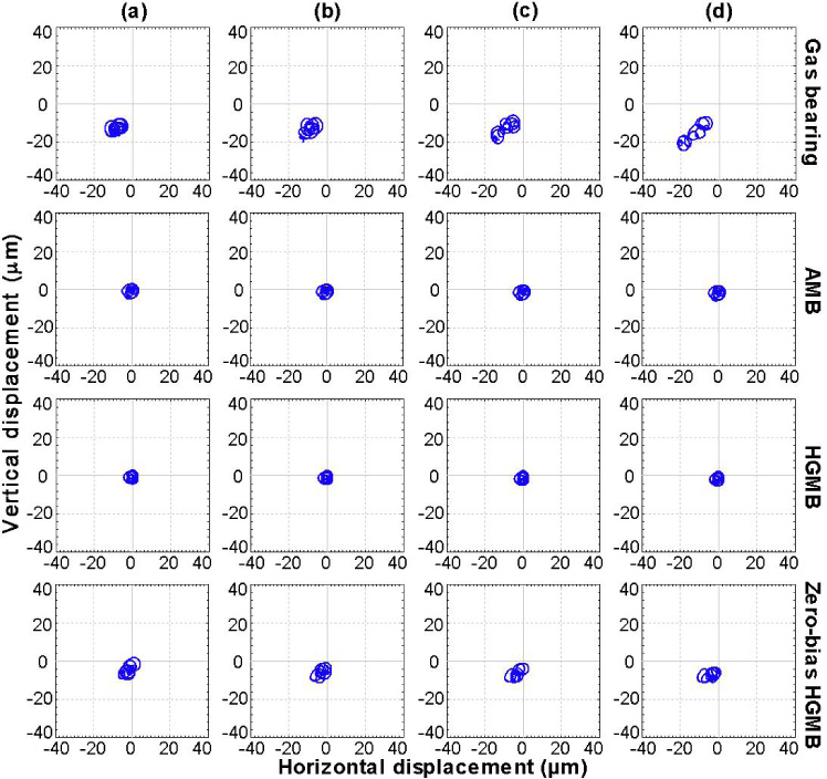
Figure 11 depicts the journal orbits on the bearing near the braking wheel side at 92 krpm in condition of varied horizontal external loads ranging from 0 N to 30 N (columns 1–4). Rows 1–4 represent different types of bearings i.e., pure gas bearing, pure AMB, HGMB, and zero-bias HGMB. The proportional gains for the AMB, HGMB, zero-bias HGMB are 6.8 × 10⁴. And the differential gains are chosen as 7. The bias currents for the AMB and the HGMB are 2 A. The blue solid line represents the rotor trajectory.
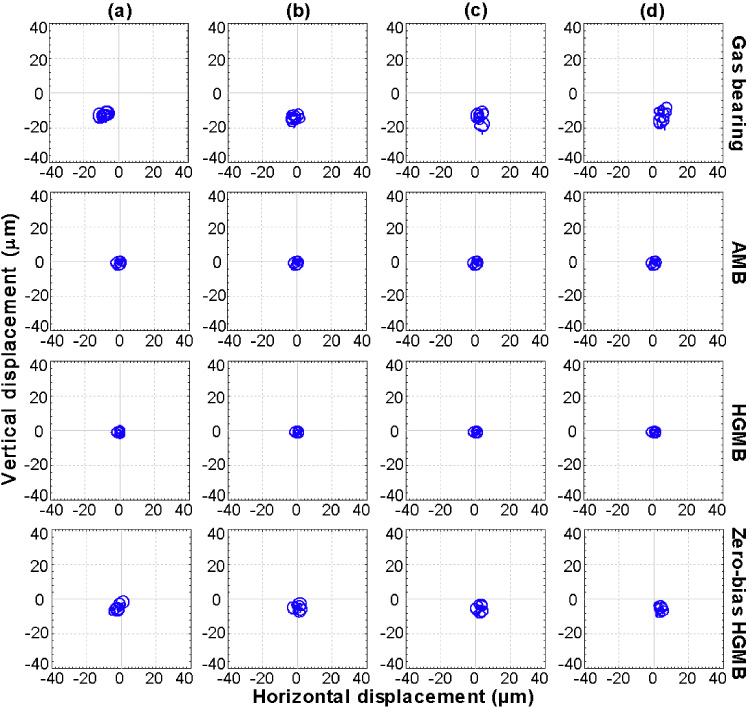
Journal orbits at 92 krpm of each bearing (rows 1–4) in condition of varied horizontal external loads: (a) 0 N; (b) 10 N; (c) 20 N; (d) 30 N.
The rotor vibration amplitudes as well as eccentricity of the HGMB are the smallest among the others, due to the enhanced stiffness, damping and load capacity. It is found that rotor vibrations of the gas bearing rotor system get larger as the horizontal external load increases. However, the addition of AMB can effectively suppress rotor vibrations. In contrast with pure gas bearing, zero-bias HGMB also possesses smaller eccentricity under horizontal external loads, indicating a larger bearing stiffness in condition of small loads.
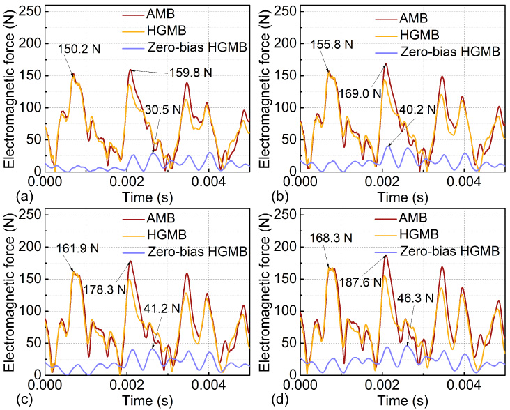
Electromagnetic forces of pure AMB, HGMB and zero-bias HGMB at 92 krpm in condition of horizontal external loads ranging from 0 N to 30 N are shown in Fig. 12. The maximum electromagnetic forces of the zero-bias HGMB are 80.9%, 78.8%, 75.6%, and 77.1% smaller than that of the AMB under horizontal loads of 0 N, 10 N, 20 N, and 30 N. And the maximum electromagnetic forces of the zero-bias HGMB are reduced by 79.7%, 76.7%, 74.3%, and 77.1% in comparison with that of the HGMB under horizontal loads ranging from 0–30 N. It is obvious that the average electromagnetic forces of the zero-bias HGMB are much smaller than that of the AMB and the HGMB.
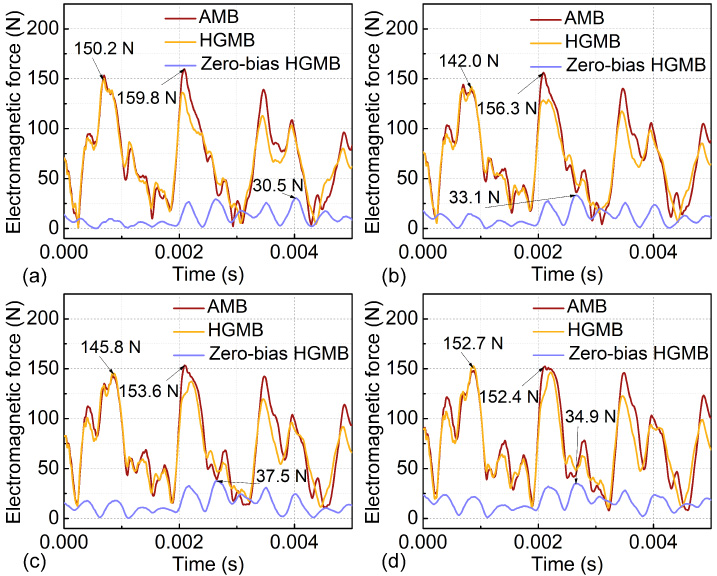
Electromagnetic forces of AMB, HGMB and zero-bias HGMB at 92 krpm in condition of varied horizontal external loads: (a) 0 N; (b) 10 N; (c) 20 N; (d) 30 N.
Since the electromagnetic force of magnetic bearing is positively correlated with coil current, meaning that zero-bias HGMB consumes less electricity than AMB and possesses larger bearing stiffness than gas bearing.
Figure 13 demonstrates the journal orbits on the bearing near the braking wheel side at 92 krpm in condition of varied vertical external loads ranging from 0 N to −30 N (Columns 1–4). Similarly, the proportional gains for the AMB, HGMB, zero-bias HGMB are 6.8 × 10⁴. And the differential gains are chosen as 7. The bias currents for the AMB and the HGMB are 2 A.
Journal orbits at 92 krpm of each bearing (rows 1–4) in condition of various vertical external loads: (a) 0 N; (b) −10 N; (c) −20 N; (d) −30 N.
Rows 1–4 represents different types of bearings i.e., pure gas bearing, pure AMB, HGMB, and zero-bias HGMB. Rotor vibrations as well as eccentricity of the HGMB are the smallest among the others in condition of vertical loads, indicating the enhanced stiffness, damping and load capacity of the HGMB. Specifically, as the vertical external load increases from 0 N to −30 N, the rotor vibrations of the gas bearing get fiercer. The application of AMB effectively suppresses rotor vibration amplitudes. Compared with pure gas bearing, zero-bias HGMB also possesses smaller eccentricity in condition of vertical external loads, indicating higher bearing stiffness in vertical directions.
Electromagnetic forces of pure AMB, HGMB and zero-bias HGMB at 92 krpm in condition of vertical external loads ranging from 0 N to −30 N are presented in Fig. 14. The average electromagnetic forces of pure AMB and HGMB increase rapidly with vertical external loads, yet that of the zero-bias HGMB rise rather slowly. The main reason is that the gas bearing also carries the load and the AMB adjusts the rotor motion for the zero-bias HGMB. The maximum electromagnetic forces of the zero-bias HGMB are reduced by 80.9%, 76.2%, 76.9%, and 75.3% in contrast with that of AMB under vertical loads of 0 N, −10 N, −20 N, and −30 N. And the maximum electromagnetic forces of the zero-bias HGMB are 79.7%, 74.2%, 74.6%, and 72.5% smaller than that of the HGMB under vertical loads varying from 0 N to −30 N. Similarly, the average electromagnetic forces of zero-bias HGMB are much smaller than that of AMB and HGMB in condition of vertical external loads.
Electromagnetic forces of AMB, HGMB and zero-bias HGMB at 92 krpm in condition of various vertical external loads: (a) 0 N; (b) −10 N; (c) −20 N; (d) −30 N.
The results manifest that zero-bias HGMB possesses enhanced bearing stiffness than pure gas bearing and consumes much less electricity than AMB under vertical external loads.
The run-up process is essential for the rotor-bearing system, especially for frequent startup and shutdown conditions. The run-up process might accelerate bearing wear and reduce bearing service life. This section conducts a transient analysis of the run-up process to understand the dynamic characteristics of the zero-bias HGMB during startup, providing a reference for bearing structural design, and avoiding excessive vibration or friction during startup.
Journal displacements during the run-up process from 0 to 100 krpm are demonstrated in Fig. 15. Specifically, vibrations of the zero-bias HGMB near the braking wheel side and the expansion wheel side are relatively more violent than that of the pure AMB and the HGMB at lower speeds. However, the maximal vibration amplitudes of the AMB and the HGMB at the expansion wheel side are 34.7% and 29.2% larger than that of the zero-bias HGMB during the run-up process.
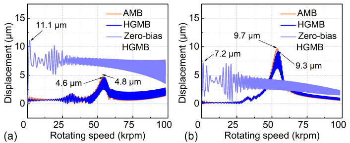
Rotor responses during startup: (a) at the braking wheel side, (b) at the expansion wheel side.
Figure 16 denotes the electromagnetic forces of distinct bearings during the run-up process. The maximal electromagnetic forces of the AMB and the HGMB near the braking wheel are 3.7 times and 3.5 times larger than that of the zero-bias HGMB. And the maximal electromagnetic forces of the AMB and the HGMB near the expansion wheel are 17.0 times and 16.1 times larger than that of the zero-bias HGMB.
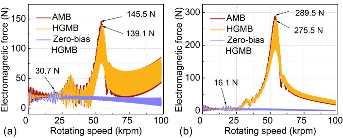
Electromagnetic forces during startup: (a) at the braking wheel side, (b) at the expansion wheel side.
Considering that the electromagnetic force is proportional to the coil current, the zero-bias HGMB can significantly reduce power consumption during the run-up process, indicating great suitability for cryogenic turboexpander. Specifically, since the HGMB at the braking wheel side carries the main load and the HGMB at the expansion wheel side bears a small load, zero-bias HGMB is well-suited for the small load occasions to reduce rotor vibrations and power consumptions.
Aimed for ultrahigh-speed occasions with frequent start/stops, a single-structured hybrid gas-magnetic bearing without bias currents has been studied. The vibration performances and electromagnetic forces of the proposed bearing has been simulated. The main conclusions are as follows. Rotor vibration amplitudes and eccentricity of the HGMB are the smallest than among the others, indicating that the combination of AMB and gas bearing significantly boosts the bearing performances. Rotor vibrations of the gas bearing get fiercer with external loads. However, the addition of AMB can effectively suppress rotor vibrations. Zero-bias HGMB possesses an enhanced bearing stiffness than pure gas bearing and consumes much less electricity than AMB under horizontal and vertical external loads. Zero-bias HGMB is well-suited for the small load occasions to reduce rotor vibrations and power consumptions during the run-up process, indicating great suitability for cryogenic turboexpander. In view of energy consumption, the average electromagnetic forces of zero-bias HGMB are much smaller than that of AMB and HGMB in condition of horizontal and vertical external loads, as well as during the run-up process, showing that zero-bias HGMB consumes less electricity than HGMB and AMB.
Footnotes
Acknowledgement
The authors are grateful for the research fund of Fundamental Research Funds for the Central Universities (Grant No. FRF-TP-22-034A1).