
Abstract
In recent years, China’s railroads have been rapidly developed, but to improve the quality of service to customers and the rapid passage of passengers is a major problem facing the railroad operation. It is the era of information development at present, China’s railroad operation has also been unprecedented rapidly developed and has significant achievements. In order to meet the growing demand and improve the level of information technology, the information system platform for railroad freight transportation has been created, because each system is not connected with each other and is independent of each other, thus creating an upgrade of the system. To solve the above-mentioned problems, it is necessary first of all to establish an intelligent freight station inquiry system, which is one of the ways for the customers to experience the convenience directly. In this paper, by understanding and analyzing the inquiry system of freight stations, we address the shortcomings and deficiencies of the system now. Using the development concept of information technology and the general development goals of Chinese railroad passenger and freight stations, the development has been carried out through the two levels of the total structure and performance of the system. Current successful modifications and enhancements of the Chinese train transportation system show promising experimental results. It has been confirmed by these tests that the system demonstrates a high level of stability and dependability while skillfully meeting the intelligent inquiry needs of travelers at railroad freight stations.
Keywords
Introduction
With the rapid development of our national railroad, the service quality of freight station is more important to the passengers, freight station network inquiry platform system is one of the important platforms to serve the passengers, requiring it taking the travel service needs of the passengers as the starting point, refer to the international leading level, constantly improve and enhance the service level, so as to bring safe and fast, comfortable and satisfactory, civilized and harmonious transportation services for the passengers [1, 2]. The important conversion frame of Railroad wagons are springs and damping springs, which can play the role of transmission of the weight of the vehicle suspension springs, reduce the dynamic load on the vehicle vibration generated, improve the efficiency of vehicle operation, but also can effectively reduce the conflict between different parts of the vehicle, vehicle and route. At present, the spring detection equipment are mostly adopted in the railroad, while manual detection section is needed, through the single spring one by one for detection, and work can be matched and combined by finally use the staff and robot work. In this way, the work efficiency is low at the same time, which cannot achieve complete intelligence, it has low efficiency results, cannot reach the high standards of the railroad. The current development goal of the railroad is high-speed, heavy-duty, but for the operation of the vehicle to go will be higher [3, 4, 5].
How to improve the intelligence and machinery during the wagon bogie spring overhaul, improve the quality of overhaul work and production efficiency, promote or overhaul equipment optimization and upgrading, we research and develop a kind of the same direction of rotation of the two groups of springs to work as an intelligent discrimination, intelligent configuration, transmission performance combined with an intelligent modern equipment, for different styles and models of wagon springs to identify and spring configuration of Performance [6, 7]. The WEB business of freight transport is opened, and the e-commerce business of railroad freight transport is opened to increase the efficiency of freight transport. The current system information background is used as a basis for the establishment of information systems for freight transportation, and the system information is improved by integrating the performance of railroad operations and e-commerce information. It is also possible to further develop the functions of railroad cargo transportations to extend them to logistics, warehouse storage, intermodal distribution and related business processes such as packaging. According to the established information platform for cargo e-commerce, mutual and ready communication is established. E-commerce shall be used on the freight platforms. With the existing application information platform system as the basic premise, Freight stations shall establish the railroad freight transport system platform, in accordance with the combination of railroad operations and sales and electronic commerce to improve freight operations and sales information platform system [8, 9, 10].
For the system upgrade this phenomenon, this paper here highlights and discusses the construction of the information system platform in the freight station, through starting upgrading and integrating each separate information system so that the data can be shared between railroad freight information platforms. The system rate firstly mentions the best solution for the self-control and configuration of bogie springs of wagons, and verifies it in the factory, which frees the human from the management and configuration of springs and largely drives the intelligent upgrading of the railroad industry. The system uses industrial intelligent robots in the process of spring overhaul to complete automatic spring handling, selection and scientific management, which has far-reaching significance for improving the level of automation and intelligence of railroad equipment and increasing the adjustment of railroad overhaul equipment structure. The non-contact linear magnetic encoder technology is presented in this research in a novel application for accurate control of a laser and camera system in spring vision tests. The technology uses camera imaging and laser triangulation to generate a spatial 3D model, which allows precise object identification, assessment of 3D appearance, and positioning for spring testing. A balance between resolution and range is essential for determining the target’s vertical offset, which is found by catching laser light reflections. Spring height and radius are computed, 3D point cloud data is analyzed, and springs are categorized according to predetermined criteria using the intelligent vision sensor module. To achieve efficient testing, categorization, and configuration, the system integrates an automated robot for intelligent spring configuration. A six-axis industrial robot, quick testing times, and good static test accuracy are examples of technical indications. To improve data efficacy and centralized management, the 3D vision inspection center gathers spatial data, and the network inquiry system of railroad freight stations is updated. These upgrades solve issues with the current independent management mode.
The remaining portion of the research is as follows: In Section 2, the goals of the study are contrasted with those of other studies of a like kind. Additional details on the study methodology are provided in Section 3. The findings of this investigation are shown in Section 4. Conclusion to Section 5.
Spring intelligent detection and classification methods
(1) Three-dimensional visual inspection technology: The system uses self-developed 3D intelligent camera sensing model, hardware system integration and self-developed software, combining the leading international technologies into one, which are: 3D laser scanning technology, 3D machine vision and environment modeling technology, 3D environment discrimination technology, 3D optical imaging and light rendering virtual technology and 3D point cloud analysis and disposal [11, 12].
Problem statement
This study presents a comprehensive solution that combines laser triangulation, intelligent robotics, and non-contact linear magnetic encoder technology to address issues with vision-based testing and configuration of springs in railroad wagons. The key is to balance the vertical range constraints given by sensor size with the goal of maximizing depth accuracy. Thoroughly taking into account criteria like height, radius, and kind is necessary to obtain precise 3D vision tests for springs. Besides, the system needs to minimize the need for new springs and effectively configure springs with an intelligent robot. The data efficacy, independence, and absence of real-time updates in the current railroad freight station network inquiry platform are challenges. To fulfill passengers’ changing information needs, the report suggests upgrading the system with the goals of enhancing real-time data receipt, integrating platforms, and diversifying functionalities. Resolving these problems is essential to enhancing spring testing and railroad freight operations’ effectiveness, precision, and information exchange.
Spring vision testing process flow.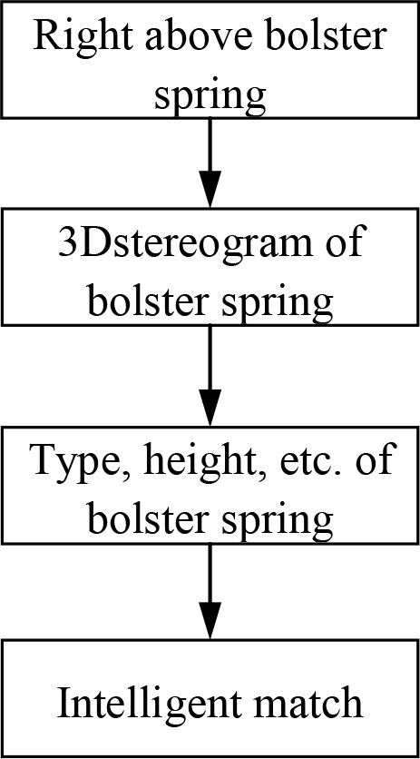
The study’s methodology uses a precision laser and camera whose positions are controlled by non-contact linear magnetic encoder technology. This allows for precise 3D environment and object data sensing. The technique uses a line laser approach to measure and identify 3D parameters such outer diameter and spring height. This strategy is based on laser triangulation and camera imaging. Figure 1 shows the vision testing procedure, highlighting the successive steps for gathering and analyzing data. An emphasis is placed on how well the system works to achieve efficiency and accuracy in spring testing. Intelligent configuration computation, robot-driven intelligent configuration system, and three-dimensional vision test categorization are all part of the process. The industrial robot and double-headed spring clamp collaborate to maximize efficiency by assessing the selection and arrangement of springs. Technical metrics are created to evaluate the system’s performance, such as static test accuracy, test time, and industrial robot standards. Along with addressing issues with data sharing and system integration, the technique also covers the design and implementation of a complete system for train freight station operations. To improve efficacy, interconnectedness, and real-time information availability, the study recommends updating the network inquiry system for train freight terminals. The requirement for additional data augmentation and subsystem integration are among the limitations. Certain projects pertaining to technical service and innovation in higher vocational colleges provide support for the study.
The non-contact linear magnetic encoder technology can be used to control the position of precision laser and camera to accurately sense the 3D environment and object data information. According to the re-established spatial 3D model, it can identify objects in space, 3D appearance measurement and positioning picking, so that the requirements of spring height and outer diameter testing can be achieved, and also real-time display and storage of test results. The spring vision testing process is shown in Fig. 7. The flow of the vision testing process in spring is shown in Fig. 1. It gives a brief visual summary of the main parts of the system and how they work together. The line laser method is apparent, utilizing both camera image and laser triangulation. With regard to detecting 3D environments, measuring spring height and outside diameter, and presenting real-time results, the graphic illustrates the sequential procedures involved in data capture and processing. Its usefulness in attaining accuracy and efficiency in spring testing procedures is highlighted by Fig. 1, which provides a succinct summary of the system’s capabilities.
The system uses a line laser approach, using the principle of laser triangulation, by being informed of the laser point to the object being tested, and then using the camera to get the image of the point, with a baseline gap between the laser projector and the camera. If the laser point is extended as a line, the triangulation data can be obtained through the data on this line, and all other information data in the face can be obtained by moving the laser line in the horizontal and vertical directions.
The vertical offset of the target is determined by the sensor by capturing reflections of laser light at different places. Optimizing depth precision makes the sensor more sensitive to positional offsets, so even small variations in the target’s vertical distance cause noticeable position shifts. Limiting target position variability is therefore necessary. On the other hand, because of limitations on sensor size, a wider vertical range for a wider variety of depth options reduces measurement resolution. An expert vision system designer must carefully balance range and resolution since the system’s ability to identify depth depends on the sensor’s ability to measure changes in reaction to reflected laser light. The principle of triangulation of distance according to the point laser is shown in Fig. 2, and the principle of imaging according to the line laser architecture light in three dimensions is shown in Fig. 3.
Triangulation distance principle of point laser.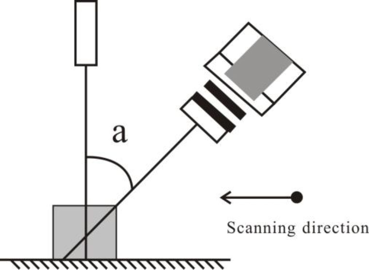
parametric variables of the bolster spring technology.
Line laser scanning three-dimensional imaging principle.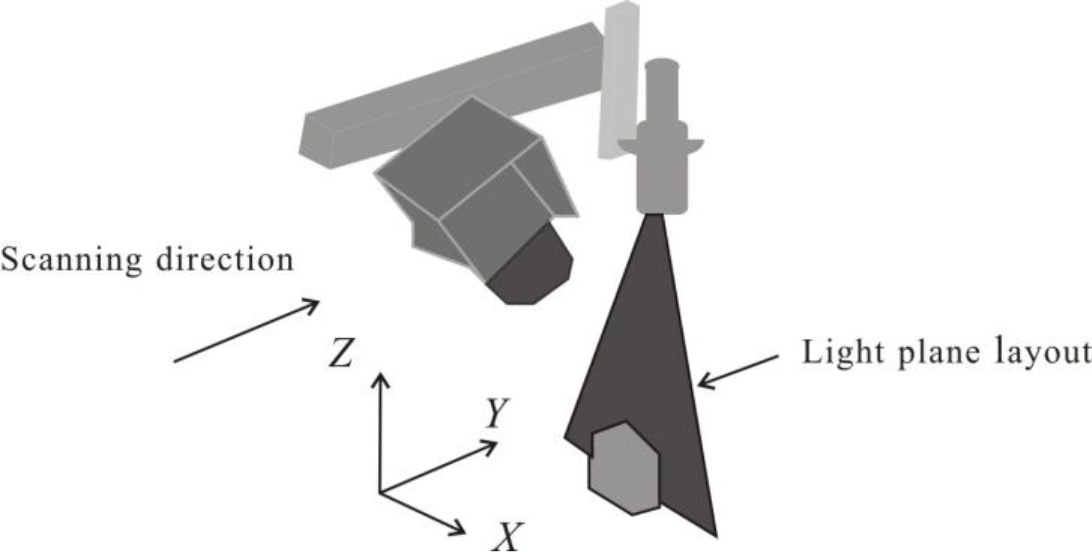
(2) Three-dimensional vision test classification method: The intelligent vision sensor module is used to scan the spring at the test station on the conveyor line and collect the three-dimensional point cloud information, then the point cloud data information is analyzed according to the three-dimensional test calculation method, and the height and radius test values of the spring are calculated, and the type and quantity of the spring and whether the spring is qualified are analyzed according to the test values [13, 14]. The principle is that the database of the main control platform stores the range of parameters for each type of K2 and K6 springs that need to be tested, and each spring test value (height and radius values) is analyzed by the main control system based on the 3D vision test. If it is within the range of the spring characteristics, then it is determined that this is the type of spring. The parametric variables of the bolster spring technology are shown in Table 1.
By using the spring principle of the directional frame and the intelligent way of model development, the spring test reference quantity, which includes the spring of the configuration area, cache area, and new spring area, is summarized, finally we get the synthesis of many springs, and then match to the most suitable spring combination by this synthesis spring [15, 16]. This spring collection is realized by the current configuration principle in the stay configuration area, and if the springs that do not reach the configuration principle are transferred to the cache area, the springs that reach the configuration principle in the cache area are about to be matched in the configuration session. If the number of matched springs does not reach the demand, it is necessary to fill them from the new spring block.
The task of selection and configuration is carried out by an intelligent robot, which at the same time performs a better optimization. The intelligent robot is a combination of a main body and a double-headed spring clamp. The robotic arm of the robot achieves the block assignment of springs by setting multiple lengths of trajectory and observing the difference between the experimental and configuration results, and placing both the unqualified springs and the configuration springs with those that fail to meet the standard in the corresponding blocks through the shortest lines accordingly. The intelligent double-headed fixture can be used to achieve the function of grabbing the spring both inside and outside without replacing the fixture, which greatly improves the work efficiency. The self-developed integrated structure of transmission, testing and configuration achieves the output of two coils of springs of the same bogie according to transmission, testing and configuration, which largely improves the working efficiency of the system.
Setting of robot intelligent configuration system solution
System plan distribution diagram.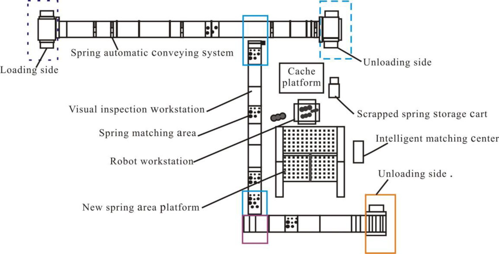
Considering the efficiency of spring testing and configuration and the direction of intelligent and automated development of inspection and repair work, the robot automated configuration platform and the bogie visual testing setup of railroad wagons use the full-disk spring automatic transmission, testing and classification and configuration method, mostly consisting of four parts, including the full-disk spring automatic transmission system and the 3D visual inspection work center, the intelligent configuration station, and the configuration center of the robot. The composition of the system is shown in Fig. 4.
Important technical indicators of the system.
Test object: height values and radius values of the spring. A spring’s height and radius values are measured using the test item. This evaluation guarantees precise dimensions attribute-based characterization and classification of springs, facilitating quality control and parameter compliance in a range of industrial applications. Static test accuracy: 0.1 mm. The accuracy of a measurement system in determining stationary positions is known as static test accuracy, and it is defined as 0.1 mm. This means that when the system is in a static or non-moving state, it can measure and keep accuracy within a 0.1 millimeter deviation. The time of the test: 3 s. The time allotted for carrying out the assessment or examination is represented by the test length, which is fixed at 3 seconds. Within the testing procedure, this predetermined timetable guarantees speed and efficiency. The number of axes of the industrial robot: 6 axes. The six axes on an industrial robot stand for the six degrees of freedom it possesses for positioning and movement. With this arrangement, the robot may move and articulate more freely, which improves its capacity to carry out tasks precisely and adaptably across a range of applications. Maximum working radius of the industrial robot: 2050 mm. The industrial robot’s working radius, or the maximum distance the arm can extend from its base, is 2050 mm. The robot’s operating range and spatial coverage during tasks in a particular workspace are determined by this parameter, which is very important. Load of the industrial robot: 45 kg. With a weight capacity of 45 kg, this industrial robot can handle and operate things up to this set limit in a variety of applications, demonstrating its strength and adaptability in automated activities and processes. Repeat positioning accuracy (RP) of the industrial robot: 0.05 A feature of industrial robots that emphasizes their dependable and extremely accurate repeatability in carrying out tasks is their Repeat Positioning Accuracy (RP), which is defined as their capacity to precisely return to the same position with a range of 0.05 to 0.06 millimeters. Work efficiency of the system: each pallet (half bogie spring) takes less than 3 min on average. Each pallet, which contains half of a bogie spring, is processed in less than three minutes on average, demonstrating the system’s work efficiency. This short turnaround time indicates how quickly and efficiently the system can accomplish the processes related to railroad wagon spring testing, classification, and configuration.
The spring automatic transfer system consists of a multi-speed chain transfer line, a double-layer automatic cornering mechanism, a guiding mechanism, an automatic lifting mechanism and a jacking mechanism. The two sets of springs of the same bogie are placed in the upper tray of the multi-speed chain transfer line and transferred to the 3D vision test center [17, 18]. The tray is output to the spring device’s station after passing through the spring test station and configuration the corresponding station, and after the assembly is completed, the empty tray is transferred to the lower part of the line by the multi-speed chain and transferred to the station where the spring disassembly starts according to the lifting mechanism to achieve the intelligent recycling of the spring’s tray. The full coil of spring automatic transfer platform is shown in Fig. 5.
Three-dimensional vision intelligent test center
The 3D vision inspection center is used to collect the corresponding spatial information data and quantity distribution of the whole spring, calculate the radius and height values of the spring, and discern the type of spring and the type of spring, so that it can provide strong information support for the intelligent selection and configuration center to start the selection and configuration decision of the spring and the action of the selection and configuration by the robot selection center. The hardware part of this center contains the module set for 3D structural light imaging, the orientation moving electric cylinder and the assembly outer shell. The software part contains the 3D point cloud module and the spring data testing module [19, 20].
Plan of automatic spring transfer platform distribution plan.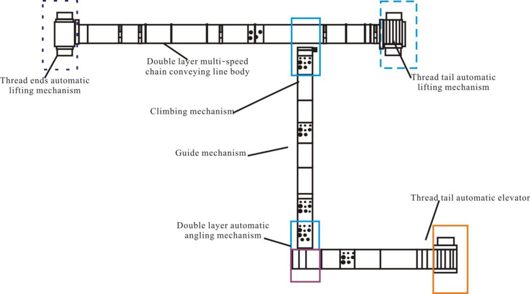
Hardware design
The hardware system consists of a 3D structured light imaging module, an azimuthal moving cylinder, and an assembled housing, most of which are used to develop the 3D imaging design for the spring.
1) Three-dimensional structure of the optical imaging module packaging
3D structured light imaging module set.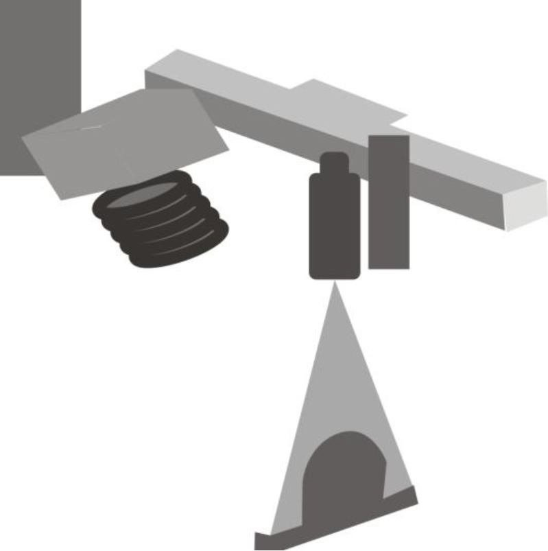
The 3D structured light imaging module is an important component to obtain 3D data information, which directly affects the resolution, accuracy and efficiency of 3D structured light X and Z orientation testing [21, 22]. Technical parameters of the light imaging module set of 3D structure: 1, the resolution of imaging: two million pixels; 2, laser energy: 120 mW; 3, 3D high-definition resolution:
2) Azimuth moving electric cylinder
The azimuth moving electric actuator is the unit that manipulates the Y orientation of the 3D structured light, and its displacement resolution, positioning accuracy and movement speed directly affect the imaging resolution, image distortion change and imaging efficiency corresponding to the Y direction.
Displacement cylinder.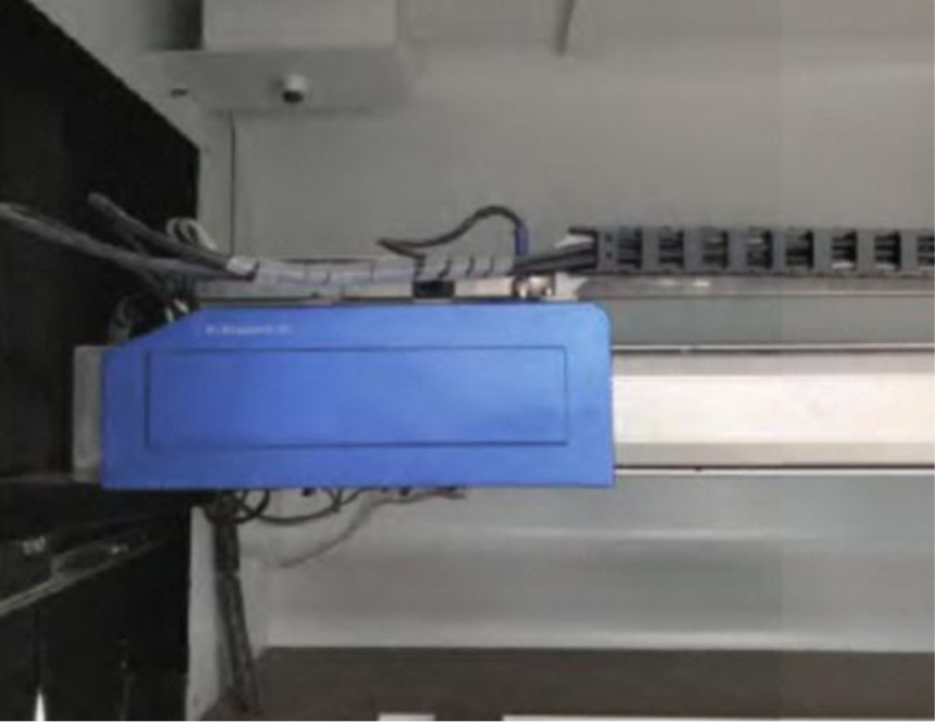
Type selection is conducted for the azimuthal motion electric actuator according to the requirements of the application of the scene and the use of theoretical knowledge. According to the size of the outside of the full disk spring, imaging resolution, accuracy and speed requirements, the total stroke of the azimuthal moving cylinder 1200 mm, the maximum movement rate of 1500 mm/s. The azimuthal moving cylinder is shown in Fig. 7.
3) Shell mounting
Shell mounting.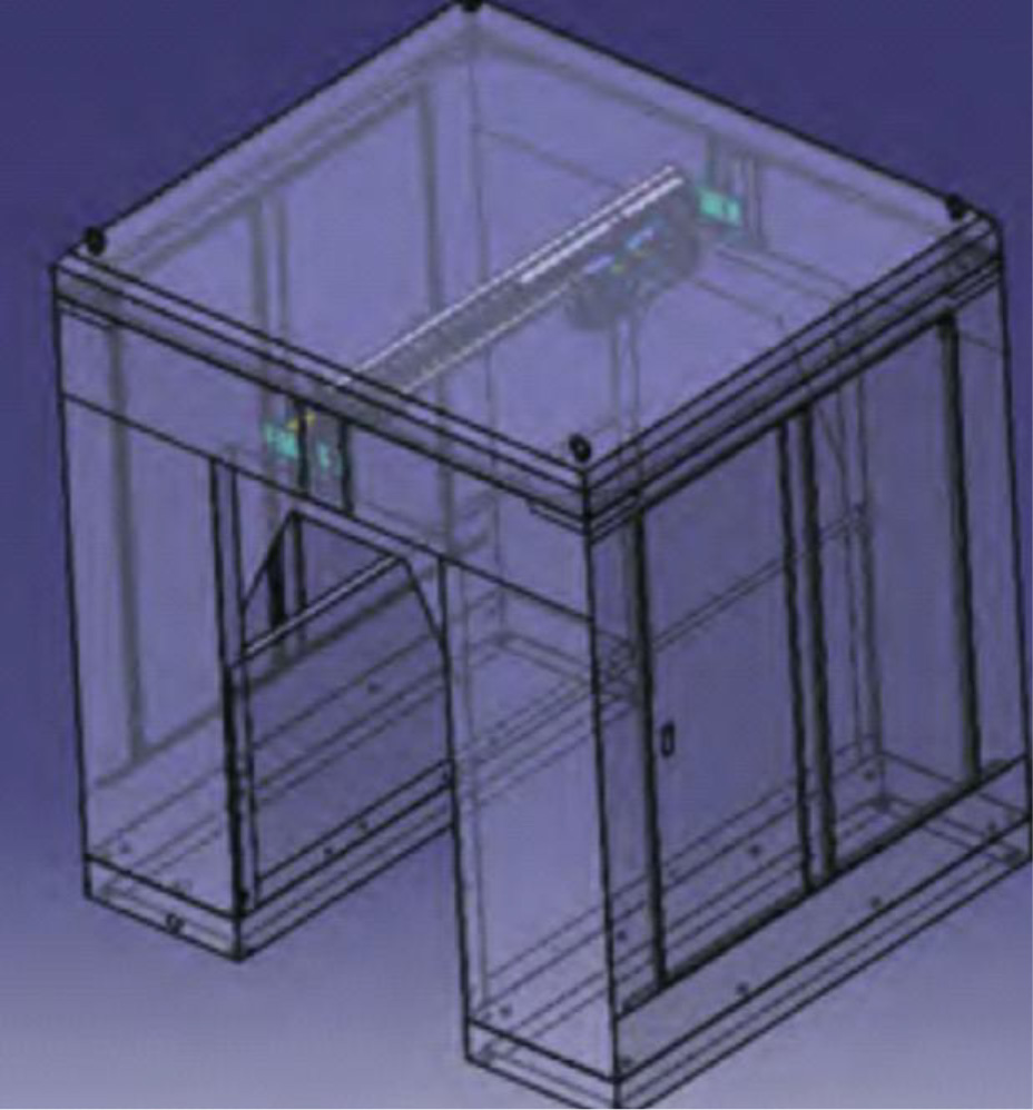
The housing mounting bulk is a combination of a shading housing, a three-dimensional structured light imaging module mounting mechanism, and a horizontal displacement electric cylinder mounting mechanism, as shown in Fig. 8 [23].
The blackout housing is made of carbon steel, and the access doors are reserved on both sides of the housing in consideration of internal inspection, repair and adjustment as well as replacement of spare parts.
Three-dimensional light imaging module installation and horizontal displacement electric actuator assembly is performed by the aluminum alloy processing and then oxidation, three-dimensional light imaging module and horizontal displacement electric cylinder according to the corresponding mechanism assembled in the interior of the shading shell.
Software design
Part of the software contains a 3D point cloud acquisition module as well as a spring data testing module. The 3D point cloud module acquires the full spring 3D point cloud information data based on the 3D optical imaging module in the hardware section. The spring data test module develops the test calculation method based on the selected design tool and the spring profile information data collected by the hardware [24, 25].
Procedure diagram of test calculation method.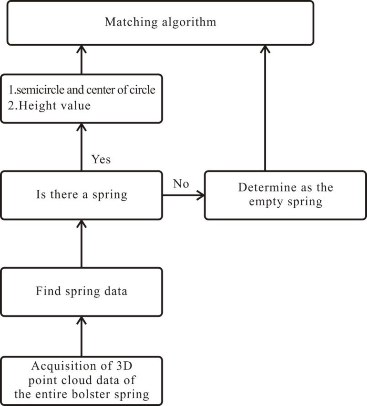
The test calculation method is used to test the height and radius of the spring according to the test requirements, and transmit this information to the selection calculation. The selection calculation method selects the one that meets the standard according to the value of the test spring information and the inspection and repair process. The IPC transmits the corresponding instructions to the robot to execute the selection action according to the software selection calculation result. The steps of the test calculation method are shown in Fig. 9.
The intelligent selection center is a combination of hardware and software. The hardware is mainly the industrial control machine and touch screen display for the main control system; the software platform system is also the intelligent picking control software prepared in accordance with the bogie spring inspection and repair process standards and regulations [26, 27].
The platform classifies the spring test data in the selection area according to the corresponding spring specifications and model parameters, and then counts the springs of each type. Within the springs in the selection area, the cache area and the new spring area, an outer spring is selected that meets the height criteria between the outer springs and meets the quantity requirements, and then the outer springs are paired in order according to the inner and outer spring configuration requirements and the inner spring configuration criteria.
The total number of springs in the configuration area and the cache area is greater than or equal to the number of springs required, so that the best combination of springs can be selected by selecting as many groups of springs that meet the criteria, replacing as few springs as possible, using as few new springs as possible, and keeping as many springs in the configuration area as possible, according to the best principles.
After selecting the best group of springs, there are requirements for the order of operation of the robot arm. Mechanical gripping and releasing springs are all internally supported gripping gas operation, and the configuration area is the inner spring placed in the outer spring, so gripping and releasing the outer spring must ensure the corresponding inner spring, so the order of gripping should comply with certain rules to make it as little as possible to reduce the mechanical clamping operation. The robot first takes away the inner spring that needs to be taken away from the configuration area, then takes away the outer spring, and afterwards puts in the outer spring that needs to be placed into the configuration area, and finally puts in the inner spring in the configuration area.
The robot configuration center
The robot configuration center consists of a combination of ABB industrial robots and a configuration mechanism system platform. The robot requires I/O boards to be connected to PLC I/O modules according to the Device Net network. Robot start-up is controlled by the PLC; the robot communicates with the main control system according to the TCP/IP protocol, and the main control platform system controls the robot to carry out configuration operations [28, 29].
The configuration mechanism system is a combination of optional, new spring cache, and, waste spring area. The industrial robot performs the operation as decided by the scheme of the intelligent configuration center, transferring the spring to the corresponding configuration mechanism system platform.
The scrap zone is a combination of the scrap spring trolley, where the detected springs are placed directly into the scrap spring trolley if they do not pass the test.
The cache area consists of a caching system. The tested qualified springs, which temporarily do not have a way to be configured to the right spring according to the spring configuration process, are put into the cache area to wait for another configuration.
The new spring area consists of a double-layered platform of new spring storage system. Currently, when the springs in the configuration area and the springs in the cache area are not available to go through the configuration, the robot grabs the springs that meet the requirements in the new spring area and completes the configuration process.
Flow of operational data information of railroad transportation cargo.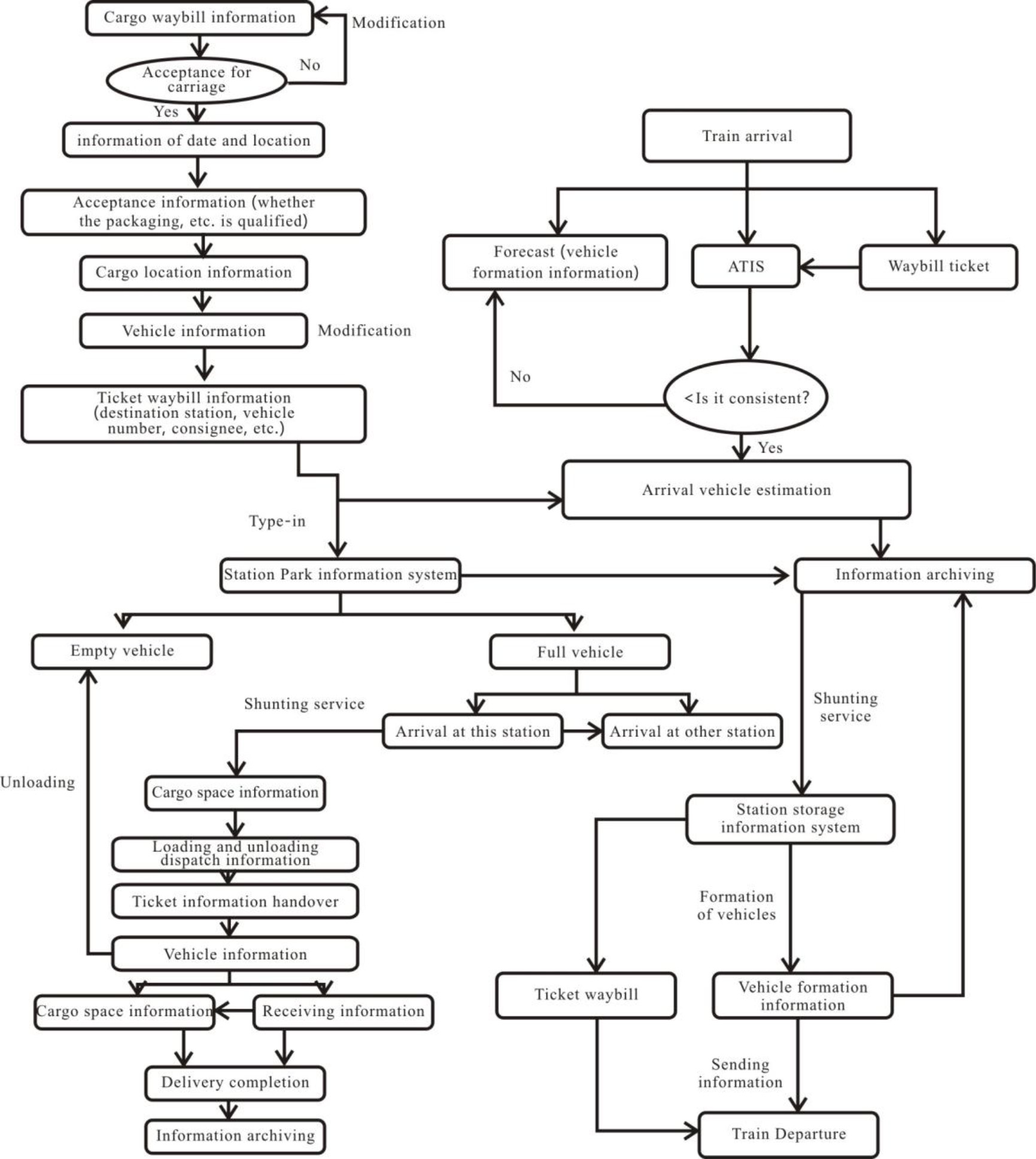
Upgrading of the network inquiry system of railroad freight stations
The network inquiry system of railroad freight stations is mainly used for organizing the operational processes of cargo transportation work in various time periods. In the process of railroad cargo transportation, inquiries will be made according to the corresponding network information on cargo transportation, mainly due to the lack of emergency green channels at railroad freight stations, which also makes it impossible to share information. Enhancing the effectiveness and interconnectivity of freight transportation operations is the main goal of the Railroad Freight Stations Network Inquiry System Upgrade. at order to test springs at railroad freight stations using 3D vision, the study presents a comprehensive system that includes precision laser, camera control, and non-contact linear magnetic encoder technology. A line laser approach employing laser triangulation and camera images is used in the 3D vision assessment. The system computes test values for height and radius, examines the 3D point cloud data of springs, and assesses the kind and quantity of springs. By refining the procedure for effective spring handling, an intelligent robot makes choices and configures itself depending on the outcomes of 3D vision tests. A 3D vision inspection center and a full-coil spring automatic transfer platform are also included in the system. Accurate data collection and analysis are made possible by the hardware and software components, which enhance the overall functioning of the railroad freight station. The study also discusses the shortcomings of the current network inquiry system for train freight terminals. It suggests an integrated strategy that combines the passenger service platform with the freight station network inquiry platform for centralized management. This interface lowers maintenance costs, improves data sharing, and gives real-time information on train schedules and available tickets. When optimizing the network inquiry system and addressing the technical components of spring testing, the suggested modifications seek to improve overall efficiency, streamline operations, and increase the efficacy of data at railroad freight stations. For example, the freight station lacks a connection channel from the forwarding office to the freight office, and the information on the cargo ticket data has to be transmitted by dialing. The flow of operational data information on transported cargoes is shown in Fig. 10.
Touch-type inquiry machine, freight station network inquiry platform and maintenance terminal, etc. constitute the freight station network inquiry system. According to the service platform LAN of freight station passengers, it reaches the network connection and exchange data between system equipment [30].
Association diagram of passenger service platform and freight station network inquiry system.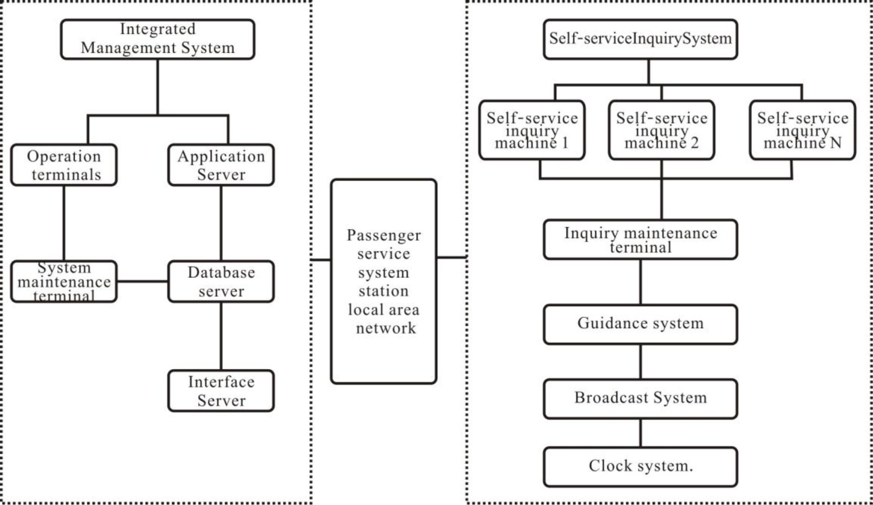
Inquiry train schedule. Inquiry is performed by train, area name, etc. The search contains information about train schedule, departure station, destination station, type of train, time of departure, time of arrival, mileage and elapsed time, etc. Inquiry of train information. You can inquire about the train number you want to purchase according to the departure train, terminal train, and area name. Inquiries about stopping information. Check the time of train stop and arriving stations, departure time and stopover time of the trains passing through. Check the fare information. Inquiry the selected date and the selected train’s fare by class. Inquiries about the basic information of the freight station, by inquiring about the floor plan; inquiring about the arrangement and service contents of the service facilities in the station; inquiring about the way of luggage storage; inquiring about the arrangement of the partition when waiting for the specified train; inquiring about the location and time of the ticket check for the specified train, the location of the platform and the seat and sleeper car, etc. Inquiries about travel strategies. Inquiry travel strategy and ticket information. Maintenance system functions. The system implements permissions, data management and remote maintenance of some functions.
At present, there are some problems occurring during the use of freight station network inquiry platform which have not been solved, especially in the following aspects.
The effectiveness of data information to be further enhanced. The current inquiry platform can be used to inquiry basic timetable information, but because of the source of information and other issues, data information cannot be updated in a timely manner, passengers cannot inquiry the immediate dynamic information, such as late trains, line changes and remaining ticket information. The current management mode of the network inquiry platform of freight stations is still relatively independent, which cannot guarantee the timeliness of data and information, so the information maintenance of the platform has a relatively large workload.
Upgrading structure of system function.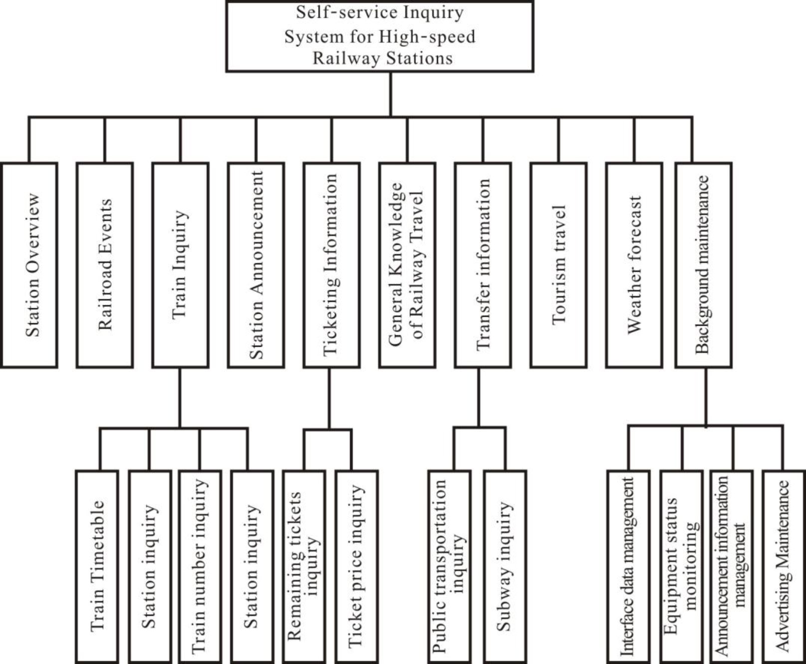
Because of the lack of comprehensive planning of railroad freight, the lack of global management guidelines, resulting in freight operations between each department are scattered, information and data cannot be shared; according to the survey, there are many newer information systems in the railroad freight station, but it is less important than system interconnection; the lack of professional support, slow progress in the construction of information technology, will limit the development of the freight industry. Because each information system was established separately in different periods and situations, there is a lack of unified construction requirements, resulting in data sharing between each subsystem and failure to achieve information communication. When inquirying the content, it is necessary to repeatedly enter the data, and the system upgrade problem is more serious. Occasionally, the number of loaded trucks is not enough and the cargo consignment application does not meet the requirements. The financial system also has problems from time to time, resulting in low efficiency of the finance department. In order to solve the problems of the web-based inquiry system, we mainly started to upgrade the design and implementation from two aspects, namely the system architecture and system functions.
In this paper, we want to integrate the freight station network inquiry platform into the freight station passenger service platform together with the guidance and broadcasting platforms and implement centralized management. Starting from the platform architecture change, according to the interface with the integrated management platform (standard TCP/IP protocol), it is possible for the freight station network inquiry system to receive real-time data such as train departure information data as well as remaining ticket information, see Fig. 11.
In this way, the data information of the freight station network inquiry system in real time is fully guaranteed, and also reduces the maintenance costs of the system.
In order to complete the recent stage of the urgent needs of railroad passengers to obtain travel information data, this paper implements further upgrade expansion and diversification of the functions of the freight station network inquiry platform, the system function upgrade architecture is shown in Fig. 12.
The basic information of passengers is available on the computer network system, which mainly contains the basic overview of the station, the record of the big railroad shipment, the frequency of wagons, the information announcement of each wagon station, the ticket information, the railroad departure schedule, the basic knowledge of travel and the basic route of station transfer. Each wagon station is able to increase the frequency in a mobile and flexible manner according to the specific situation of the freight station and special regional information. To realize the instant information of the departure, via and end of the first train of the station information to be inquired, the ticket information provides the instant ticket inquiry of each train of the departure and halfway.
Now is the era of information development, in the rapid construction of the information age at the same time the railroad also fast forward development, in the entire market operation to improve the development of power and enterprise revenue, but also reduce the cost of a number of work costs. However, the development of China’s railroad freight is a little later than other runs, when the construction of China’s railroad freight development, produced a more independent and closed information system, resulting in the occurrence of information can not be shared cannot synchronize the situation. Passenger service system better demonstrates the situation for the freight station set up as well as the use of the situation, through the use of multi-task combination, unified data information to achieve high efficiency of operation. Freight intelligent checking system is a component of passenger service system, completed through the optimization of the architecture and performance based on making the service more convenient, the use of more convenient effect. This system has been successfully operated through the national engineering test passenger service and achieved better results during the simulation operation.
Limitation
The passage does not go into detail about how China’s railroad freight development is facing, and it just briefly discusses the effectiveness of the freight intelligence checking system without offering any hard data or metrics.
Data availability
The data used to support the findings of this study are included within the article.
Funding statement
This research study is sponsored by these projects: project one: Technical service of the State Railway Administration Commission, Contract No. [2019] 19; Project two: Action plan for innovation and development of Higher Vocational Colleges in Henan Province – JiaoGao, Project No. [2017] 895. Thank these projects for supporting this article!
Footnotes
Conflict of interest
The authors declare no conflicts of interest.