
Abstract
Web shear buckling of steel plate girders limits their load-carrying capacity in bending. Several analytical models have been suggested in the literature to estimate the shear capacity of plate girders. This paper presents a critical evaluation of several of these analytical models using the data of experimentally tested plate girders available in the literature. It was found that these analytical models make a conservative estimation of critical buckling strength for plate girders with larger slenderness and/or aspect ratios. Although the predicted ultimate shear strength varied across the different analytical models, no particular trend was identified to show that the aspect and/or slenderness ratios influenced the shear strength. A parametrically conducted analysis indicated that the threshold slenderness ratio (to cause buckling in the web panel) decreases with increasing yield strength and aspect ratio. The paper proposes simplified guidelines for the preliminary sizing of steel plate girders by avoiding shear buckling. It has been shown that the sizes of plate girders determined using the proposed guidelines satisfy design requirements for both flexure and shear.
Keywords
Introduction
Steel plate girders are a common type of thin-walled steel members which are often used to support heavy loads over large spans, such as those provided in bridges. A plate girder is a built-up beam that is fabricated by welding together two flanges, a web and (generally) a series of transverse stiffeners (Fig. 1). The changing bending moment in the beam induces flexural shear. The flanges primarily resist applied bending moment, while the web provides resistance to applied shear force. The thickness of the web for the practical span lengths of plate girders is generally smaller when compared to the flanges, as the applied shear (in many cases) is relatively low compared to the bending tension and compression in the flanges and does not require a thicker web (ignoring web buckling) [1]. This smaller web thickness increases the ratio of the depth of the web (d w ) to its thickness (t w ) (known as slenderness ratio, d w /t w ) which results in elastic shear buckling of the web at low levels of loading. The webs are, therefore, commonly strengthened with transverse, longitudinal or (occasionally) inclined stiffeners to increase the elastic shear buckling strength of plate girders [2, 3]. These stiffeners also provide additional capacity in a plate girder to resist applied shear by increasing its post-buckling strength. The sum of elastic and post-buckling strength is used to determine the ultimate shear strength of plate girders. Note that other types of stiffeners may also be provided in a plate girder such as bearing stiffeners, jacking stiffeners, stiffeners for cross girders and stiffeners to resist lateral torsional buckling. These, however, are beyond the scope of work presented in this paper.
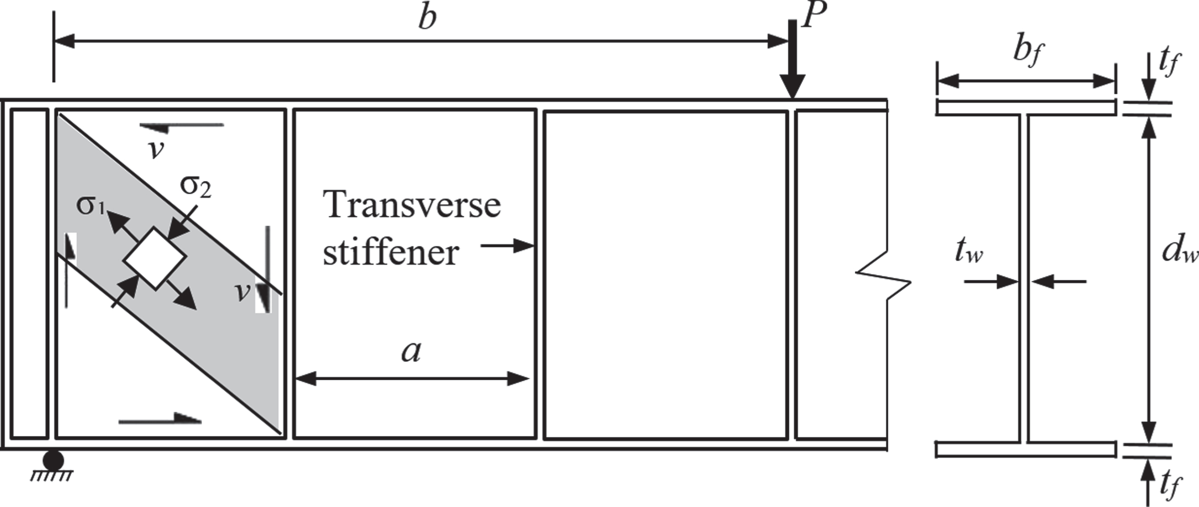
Typical steel plate girder with notations and web state of stress.
Several studies have been conducted to develop methods for predicting the ultimate load capacity of plate girders in shear [2, 4–15] which is more critical as compared to bending strength. It has been found that the critical shear buckling strength (elastic buckling strength) and tension field action of the web [16], and frame action of the flanges and transverse stiffeners contribute to the ultimate shear strength of transversely stiffened plate girders. The girder fails by excessive yielding of the web panel. Tension field and frame actions occur in plate girders with rigid transverse stiffeners provided at the girder ends, commonly known as the end posts. The design methods used for determining the elastic and post-buckling shear strength of plate girders assume that the material has an elastic perfectly plastic behaviour.
The plate girders are mostly designed such that webs are in the slenderness range where web buckling can occur. A review of the available methods to predict the ultimate shear strength of steel plate girders [5, 17–19] indicates that these commonly consider that failure in a steel plate girder is predominantly controlled by the shear buckling strength of the web which depends on critical buckling stress (τ cr ). While several studies [5, 21] have suggested that post-buckling strength is controlled by the tension field action of the web, Lee and Yoo [1] argued that this is true for very thin panels and that the out-of-plane flexural action of thicker web panels controls post-buckling strength of a plate girder. As a result, available methods for estimating the shear strength of plate girders differ concerning their post-buckling behaviours. The design theories presented by Rockey and Skaloud [9] and Hoglund [17] have been adopted by BS5950-1 [21] and Eurocode 3 (EC3) [22], respectively, while the Basler [5] theory was adopted by the American Institute of Steel Construction [23].
This paper presents an analytical investigation and reviews several methods available to predict the ultimate shear strength of plate girders without imperfection. The data from 280 experimentally tested girders available in the literature were analysed and the results of experimental and analytical shear strength were compared. A parametric study was carried out to investigate the influence of different parameters on the shear capacity of girders. Guidelines for sizing plate girders to avoid shear failure have been provided using the results of the parametric study.
The ultimate shear strength theory for welded plate girders was first presented by Basler [6, 24]. It was followed by several other theories proposed by different researchers. All these theories are based on the development of the failure mechanism in the web panel of the girder. The ultimate strength of a web panel (V u ) (which is without imperfection and is subjected to pure shear) can be taken as the sum of three shear strength components: pre-buckled strength (elastic shear behaviour), post-buckled strength (web mechanism formation) and frame action strength (panel mechanism). Pre-buckled strength refers to the elastic in-plane shear strength of the panel given by τ cr . The shear (v) at this stage is resisted by the web by beam action resulting in uniform shear stress throughout the web panel, which is given by Equation (1) [25].
Lee et al. [12] proposed Equation (4) for k for stiffened plate girders by combining k
s
and k
f
AISC [23] has recommended Equation (5) for determining k for stiffened girders
Note that k in Equation (5) is taken as 5.34 if the aspect ratio (α= a/d w ) is greater than 3.
The applied shear in the web panel of a plate girder can be resolved into diagonal principal tensile ( σ 1 ) and compressive ( σ 2 ) stresses (Fig. 1). Both these stresses remain equal until the development of initial buckling when σ 2 reaches τ cr . Any further increase in σ 2 (with increased applied load) is limited by the web panel stiffness across the corrugations and the additional shear is resisted through tensile membrane stress which varies across the web panel. The maximum intensity of the stress occurs within an inclined band of the web panel (Fig. 2) which is termed tension field action [16]. The sum of vertical components of tensile and buckling stress limits the increase in the tension field stress, as this sum cannot increase beyond the yield strength of the web in the inclined band. The tension field action contribution depends on α, d w / t w and steel yield stress ( f y ) [7].
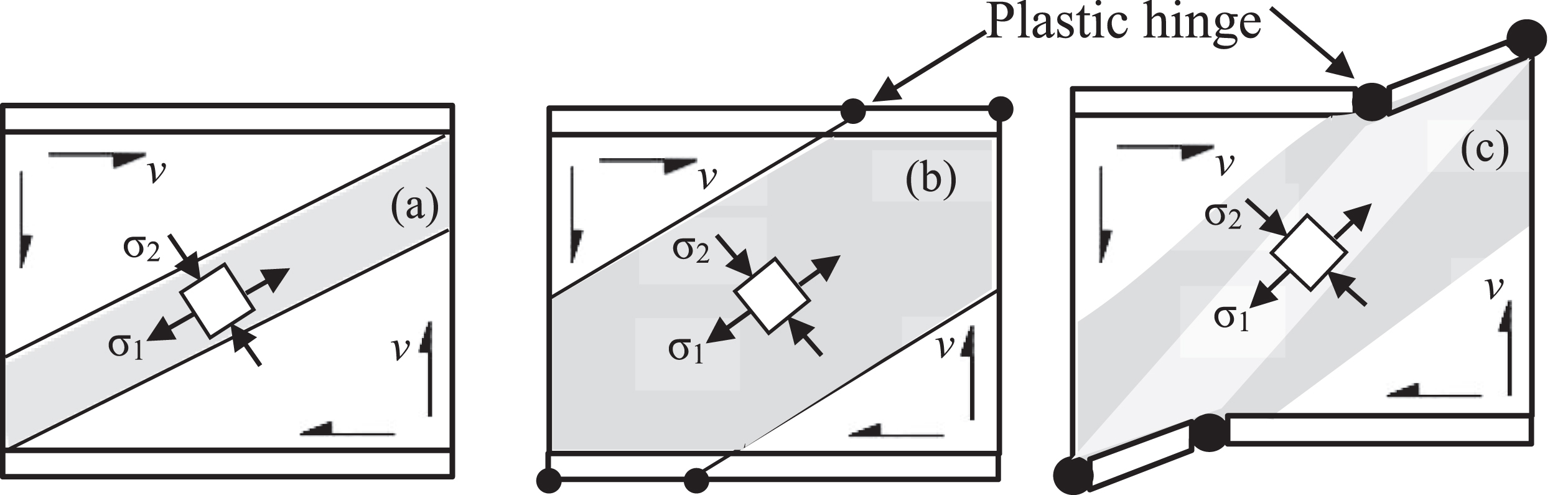
Basler [5, 6] suggested that the tension field action cannot develop in the neighbourhood of flanges, as these are not rigid enough for this to happen. The yield zone suggested by Basler [6] is shown in Fig. 2(a). On the contrary, Rockey and Skaloud [9] and Porter et al. [10] proposed a tension stress field that develops between the flanges, as shown in Fig. 2(b). These authors suggested that the resistance to the applied shear is provided by the flanges beyond this stage which resist distortion of the shear panel, termed sway frame action (also known as Vierendeel truss action) shear. The failure of the web panel is caused when plastic hinges are developed in both flanges (Fig. 2(c)), as the flanges are too thin and flexible to resist the vertical component of the tension field. Elgaaly [26] reported that the theory developed by Porter et al. [10] and Rockey and Skaloud [9] provides better results on the shear capacity of steel plate girders as compared to Basler [6] theory.
Several other researchers also contributed to the development of the present level of understanding of the behaviour of steel plate girders by conducting experimental testing such as Cooper et al. [27], Fujii [28, 29], Fujii and Akita [30], Lew and Toprac [31] and Nishino and Okumura [32].
Since web behaviour in the post-buckling stage is highly complex, it creates sizable challenges in carrying out an exact analysis [7]. As a result, different researchers have proposed simplified analytical models for use in the design of plate girders. Of these, the methods suggested by Lee and Yoo [1], Basler [5], Rockey and Skaloud [9], BS5950-1 [21], EC3 [22], AISC [23], CSA S16 [33] and BS5400-3 [34] have been employed in this paper to study the theoretical shear behaviours of end panels of steel plate girders. A summary of these analytical models is given in the forthcoming sections which is followed by a discussion on the results provided by these models. Note that plate girders for highway bridges are designed by using AASHTO LRFD Bridge Design Specifications [35] in the US. Since the design provisions for steel plate girders in these specifications are similar to AISC [23], the results obtained for the method proposed by AISC [23] apply to AASHTO [35]. Further, BS5400-3 [34] was used for the designing of steel bridges before the introduction of EC3 [21] in the UK. Finally, it is noted that S355 is the most common steel used for plate girders in bridges.
Elastic shear buckling strength
Table 1 summarises the expressions for determining the elastic shear buckling strength ( V cr ) of a plate girder panel suggested by the aforementioned analytical models. Note that different terms used in the expressions in Table 1 or elsewhere in the forthcoming sections are reproduced from the respective source of reference. Further, no explicit information on the determination of V cr is available in BS5400-3 [34].
Method for calculation of elastic buckling strength of steel plate girder
Method for calculation of elastic buckling strength of steel plate girder
Note that in Table 1 C v is the ratio of critical web shear (τ cr ) to the web shear yield stress (τ yw ) which is calculated by Equation (6); q cr is the critical shear stress of the web (similar to τ cr ) which is given by Equation (7); and E is the elastic modulus of steel. Note that given the differences in the notations for critical shear stress in Table 2, it will be denoted as v cr in the subsequent discussion in this paper.
Comparison of experimental and analytical critical shear
Note: Subscript Bas, AISC, Lee and BS stand for Basler [5], AISC [23], Lee and Yoo [1] and BS5950-1 [21], respectively.
The expression for determining k for each of the employed methods is given in Table 1. It is noted in Table 1 that although the method of determining V cr is the same for Basler [5], Rockey and Skaloud [9], CSA S16 [33], EC3 [22], and Lee and Yoo [1], the differences are resulted by the k value used in Equation (1). While Basler [5], Rockey and Skaloud [9], CSA S16 [33] and EC3 [22] suggested the use of Equation (2), Lee and Yoo [1] recommended Equation (4) for determining k. Further, (contrary to other methods) the methods proposed by AISC [23] and BS5950-1 [21] consider the direct influence of f yw on V cr . In addition, a web instability condition has been defined by AISC [23] (Table B4.1) which is given by Equation (9).
A comparison of Equations (8) and (9) indicates that (contrary to AISC [23]) BS5950-1 [21] considers both the slenderness and aspect ratios to define the web instability in steel plate girders. Finally, Basler [5] suggested that if τ
cr
is greater than 0.8
f
yw
, it is taken as
Basler [5] proposed Equation (10) for estimating elastic post-buckling strength ( V pb ) of steel plate girders considering the tension field action of the shear panel between transverse stiffeners (Fig. 2)
AISC [23] proposed Equation (11) for the calculation of V pb
Rockey and Skaloud [9] suggested Equation (12) to determine V pb for a plate girder panel predominantly loaded in shear
The method suggested by CSA S16 [23] is given by Equation (13) which considers the influence of both web slenderness and aspect ratio on V pb [36].
Lee and Yoo [1] proposed Equation (14) to determine V pb of steel plate girders.
Note that k in Equation (15) is determined by Equation (4).
BS5950-1 [21] considers separate contributions from the web ( V w ) and flange ( V f ) in resisting shear buckling [Equation (16)] provided that the flanges of a steel plate girder are not fully stressed
In the absence of specific information, the shear strength of the web panels of steel beams by BS5400-3 [34] has been considered as the ultimate strength which is given by Equation (17)
EC3 [22] does not make an explicit separation of the elastic and post-buckling contributions. The expression to determine V pb for the web panel of a stiffened steel plate girder subject to in-plane forces can be written as Equation (20), considering the contribution of the web alone in the pre-buckling resistance of the plate girder
Kwon and Ryu [37] reported that M Ed /Mf,Rd varied from 0.19–0.62 for the plate girders tested by these authors. Therefore, a central value of 0.45 has been used in this paper for this ratio and for f f /f yf (Equation (16)). It is noted in the above that both BS5950-1 [21] and EC3 [22] consider flange contribution explicitly in the post-buckling strength of a plate girder.
The data from experimental testing of plate girders reported in the literature by different researchers were gathered and analysed to understand the differences in the estimation of both the elastic and post-buckling strengths. The data from 280 experimentally tested plate girders available in the literature were used for this purpose. The details of these plate girders are given in Table A1. It is noted in Table A1 that the tested girders have large variations in cross sections, f yw and f yf , and aspect ratios. The d w /t w values of the tested plate girders in Table A1 vary from 30.77–402.52 whereas a/d w for these plate girders ranges from 0.36–17. Similarly, f yw and f yf of the plates used in these girders varied from 183–750 MPa and 149–820 MPa, respectively.
A review of the experimental data for the plate girders given in Table A1 indicated that the researchers have mostly reported the observed V u of the tested plate girders. This (perhaps) is the biggest challenge in verifying the accuracy of the analytical methods (Table 1) for the estimation of V cr . Lee and Yoo [18] presented the data from experimental testing of 10 plate girders which does not include a comparison of observed V cr with the analytical model proposed by Lee and Yoo [1]. Although Kwon and Ryu [37] reported that the observed V cr for the tested plate girders was slightly lower when compared to that estimated using Eq. (2), the data of observed V cr were not provided by these authors. Owing to these limitations, the data of V cr for the girders tested by Kwon and Ryu [37] were extracted from the plot of load-lateral displacement reported by these authors and are given in Table 2. These experimentally observed V cr (Vcr,Exp) values have been compared with the analytically estimated values in Table 2, as a ratio of experimental and analytical V cr . The analytical V cr values obtained from Basler [5], AISC [23], Lee and Yoo [1] and BS5950-1 [21] models have been used for this comparison in Table 2, as the expressions for estimation of V cr for these methods are different from each other. The obtained results from the method suggested by Basler [5] also apply to Rockey and Skaloud [9], CSA S16 [33] and EC3 [22], as the same τ cr is calculated by all these methods. The data of V cr (Table 2) for the plate girders designated as ‘Unstiffened’ and ‘Control’ were reported by Okeil et al. [62] and Bhutto [63], respectively, while the remaining girders were tested by Kwon and Ryu [37]. The properties of all the plate girders in Table 2 are available in Table A1.
The comparison in Table 2 is telling in several respects. Firstly, it is clear that the analytical predictions made by the methods proposed by Basler [5], AISC [23] and BS5950-1 [21] are similar for all the girders, despite different expressions. On the other hand, some differences exist between these and the method suggested by Lee and Yoo [1]. Further, all methods provide conservative estimates of V cr for girders with larger slenderness ratios for the same aspect ratio. Conversely, conservativeness in the estimation of V cr increases with increasing aspect ratio at a given slenderness ratio. This is due to the reason that v cr is influenced by the restraint provided by flanges [37] which is not considered by the employed analytical methods. In addition, the method suggested by Lee and Yoo [1] is more conservative at smaller aspect ratios (less than 0.6) as compared to the other methods. The opposite is true for aspect ratios larger than 0.6. Kwon and Ryu [37] have also indicated that the assumption of fixed boundary conditions results in non-conservative estimates of v cr for girders fabricated with high aspect and low slenderness ratios. Finally, it is noted in Table 2 that although R2 values for the ratio of experimental and analytical V cr data for each of the employed methods are sufficiently higher, this value is highest for the method proposed by Lee and Yoo [1] due to the reasons mentioned above. Note that R2 provides goodness-of-fit for the linear regression model. A higher value indicates a better chance of fitting the regression model with the data.
Figure 3 compares the V u obtained from the experimental data (Vu,Exp) with the values determined using the employed analytical methods. The data of 258 plate girders included in Table A1 were plotted in Fig. 3 for better clarity. The data points below the diagonal line are indicative of a conservative estimate of V u (Vu,anal) as compared to the observed value and vice versa. It is seen in Fig. 3(c) that (from a qualitative point of view) the method suggested by Rockey and Skaloud [9] provides a conservative estimate of V u for a large number of plate girders, which is followed by the method recommended by BS5950-1 [21]. This is partially due to the reason that Rockey and Skaloud [9] argued that the width of the plastic zone in the post-buckled stage is controlled by a flange flexibility factor. This results in limiting V u to V cr for plate girders with flexible flanges, neglecting any contribution from the flanges in the post-buckling shear capacity of the web panel.
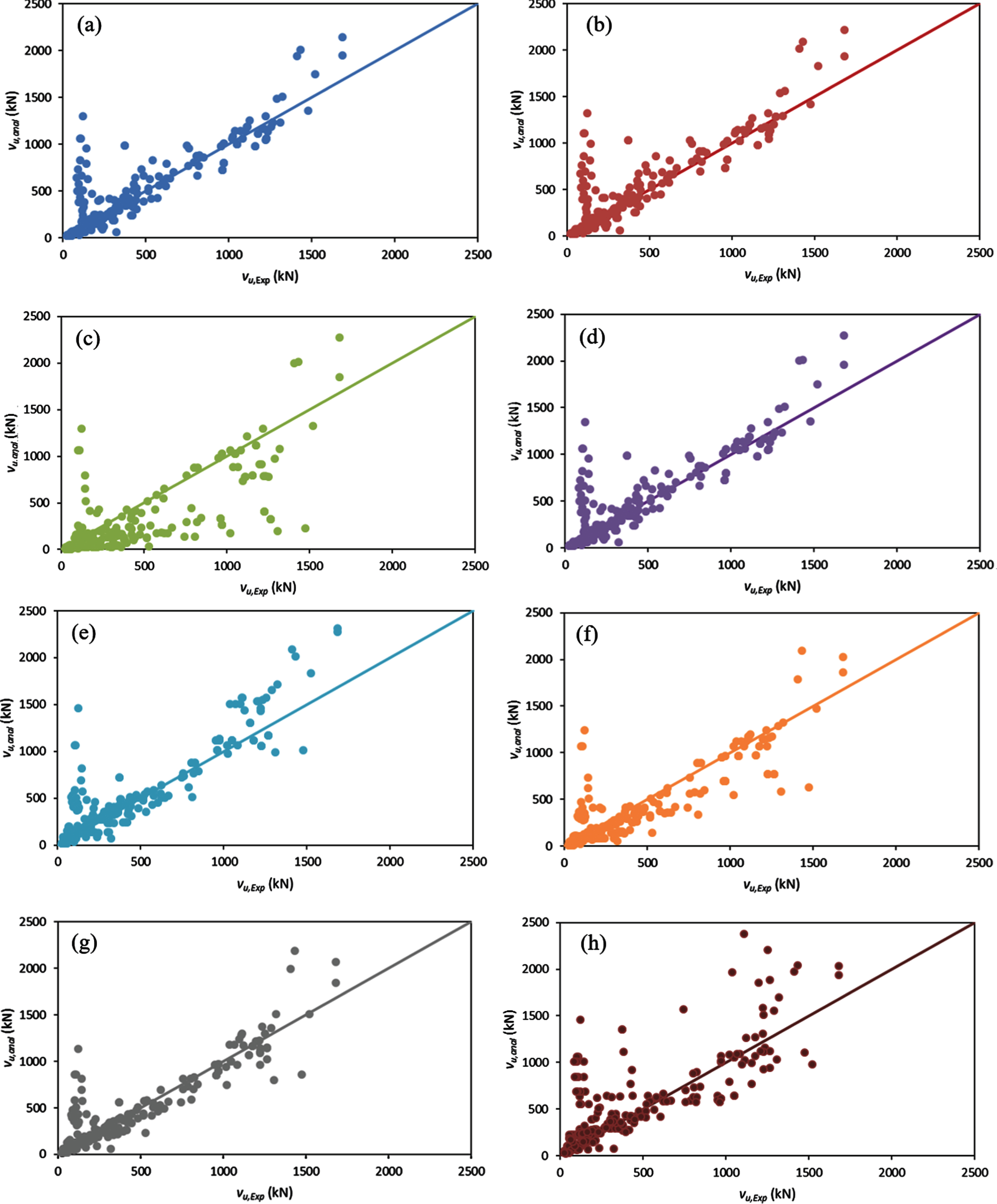
Further, it is seen in Fig. 3 that the methods proposed by BS5400-3 [34] and Lee and Yoo [1] overestimate V u for a significantly large number of girders (particularly at V u = 1000–1600 kN) whereas the least overestimation is found for the method suggested by EC3 [22]. Nonetheless, no particular trend (for underestimation or overestimation) becomes apparent in Fig. 3, irrespective of the analytical method used or the girders’ aspect and web slenderness ratios. This indicates that V u is influenced by other geometric parameters of the plate girders in a combination of the aforementioned ratios.
The statistical analysis results for the ratio Vu,Exp/Vu,anal are presented in Table 3. It is noted that the maximum and minimum coefficient of variation (CV) is found for the methods suggested by Rockey and Skaloud [9] and EC3 [22], respectively. Further, the mean, CV and standard deviation (SD) of Vu,Exp/Vu,anal are similar for Lee and Yoo [1], Basler [5], EC3 [22], AISC [23] and CSA S16 [33] although the least values were provided by the method recommended by EC3 [22] which are similar to BS5950-1 [21]. The 95% confidence intervals for all these methods are also similar to each other. Based on the comparison of data dispersion measures in Table 3, it can be inferred that the analytical predictions made by the method recommended by EC3 [22] provide the best correlation with the experimental data.
Summary of statistical analysis of ratio of experimental and analytical ultimate shear strength
A parametric study was carried out using the data of plate girder properties given in Table A1. The objective of this parametric investigation was to theoretically examine the influence of various factors upon both V cr and V u for plate girder web panels. The parametric study was carried out using the previously mentioned range of d w /t w reported by the researchers (30.77–402.52). The values of a/d w were varied as 0.36, 1, 2 and 3 which were combined with 4 values of f yw taken as 183 MPa, 300 MPa, 490 MPa and 750 MPa. The values of f yf were taken the same as f yw for all of the above combinations of parameters.
Effects on critical buckling stress
The variations in v cr based on the methods recommended by AISC [23] and BS5950-1 [21] have been compared for the abovementioned f yw values in Fig. 4. It is seen in Fig. 4 that v cr increases with f yw . Conversely, threshold d w /t w (to cause buckling at a given a/d w ) decreases at higher f yw . The above indicates that a smaller thickness for the web plate is needed at higher f yw to resist a particular level of force for the same depth of a girder. Further, v cr is nearly insensitive to f yw beyond d w /t w = 200. The results for other a/d w ratios and the methods proposed by Basler [5] and Lee and Yoo [1] are similar. Note that the threshold is the first value of a parameter where web buckling begins.
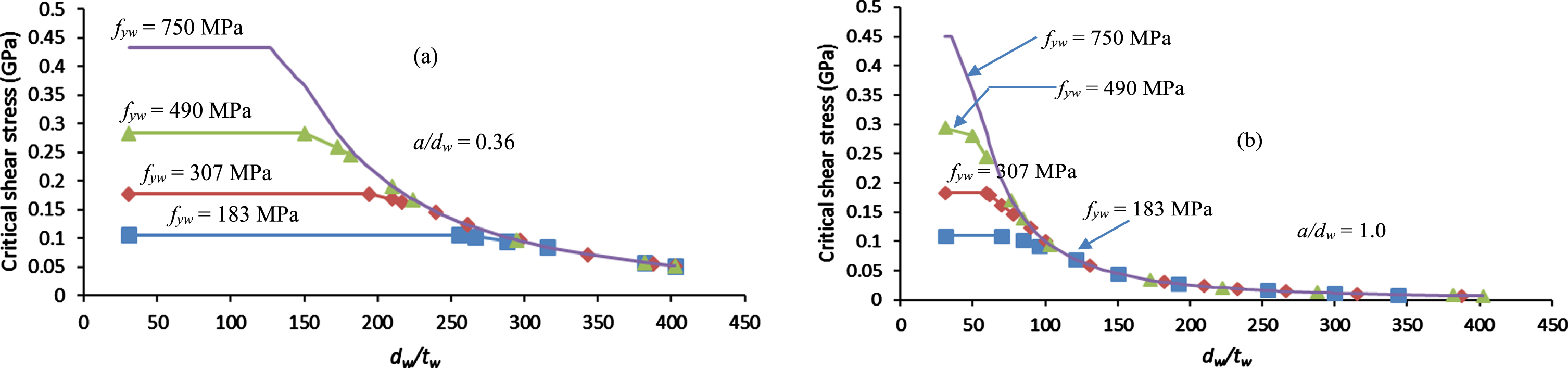
Figure 5 shows typical plots of variations in v cr at the selected a/d w values for the method proposed by Basler [5] and BS5950-1 [21]. The threshold value of d w /t w to cause buckling in the web is significantly higher at a/d w = 0.36 (in particular for the method proposed by Basler [5]) whereas this is similar to all the remaining three values of a/d w (1, 2 and 3). Further, the threshold value of d w /t w to cause buckling in the web panel and v cr (at a given value of d w /t w ) reduces significantly as a/d w is increased from 0.36 to 1. Thereafter a/d w does not affect the critical shear capacity of plate girders significantly and it remains similar at a/d w values of 2 and 3. The results in Fig. 5 are similar for other values of f yw and the method recommended by AISC [23] and Lee and Yoo [1].
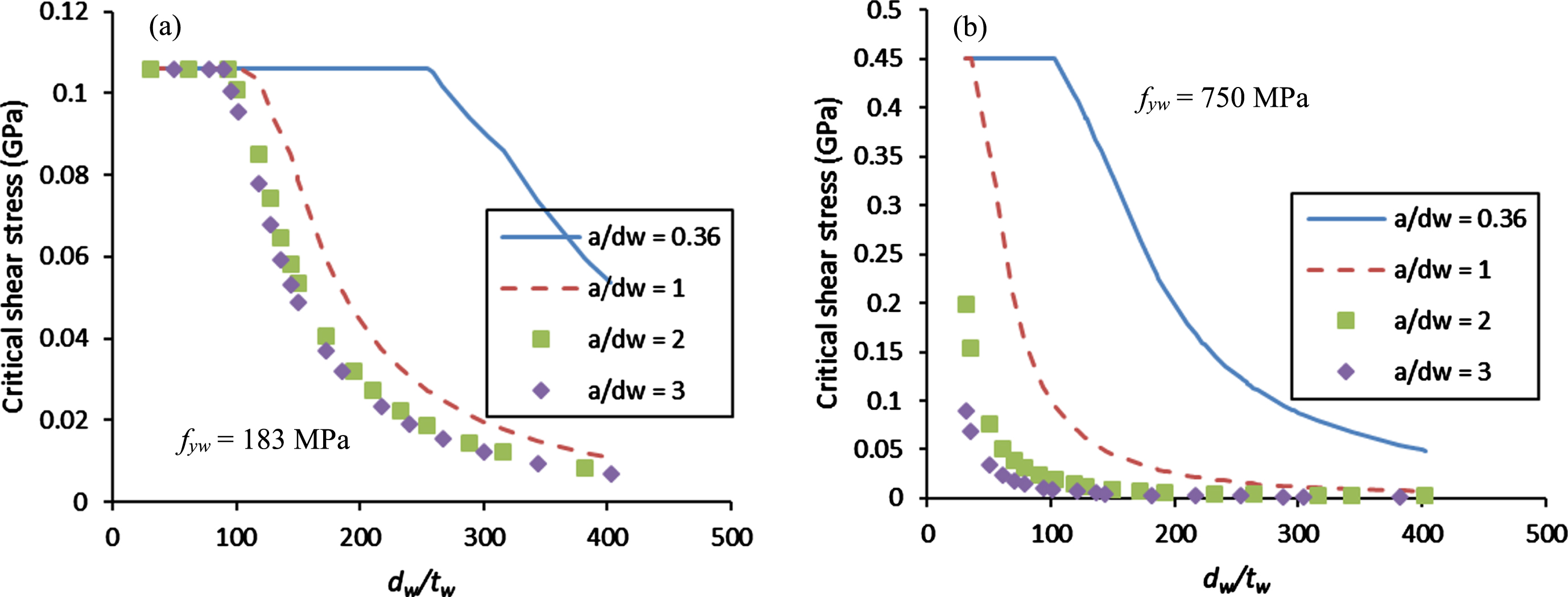
Figure 6 compares variations in v cr estimated by the employed methods at different a/d w values for f yw = 307 MPa. The plots in Fig. 6 are typical representations of all the remaining f yw values selected for this study. It is seen in Fig. 6 that the methods proposed by Basler [5], AISC [23], and Lee and Yoo [1] provide a similar estimation of v cr for a given value of a/d w . On the other hand, v cr estimated by the method proposed by BS5950-1 [21] is smaller as compared to the other employed methods. Further, v cr (corresponding to a threshold value of d w /t w to cause buckling) increased slightly for the method proposed by BS5950-1 [21], as a/d w increased from 0.36 to 1.0. This increase, however, was accompanied by a large decrease in the threshold d w /t w from 172 to 59 at the aforementioned values of a/d w . A further increase in a/d w resulted in a decrease in the threshold v cr for this method. Contrary to this, the threshold value of v cr and corresponding d w /t w decreased continuously for the method proposed by AISC [23] with an increase in a/d w . Although the value of v cr is similar to the method proposed by Lee and Yoo [1] and Basler [5] at a given value of a/d w , the corresponding threshold value of d w /t w is different. It becomes apparent in Fig. 6 that the method proposed by BS5950-1 [21] is the most conservative and the degree of conservativeness increases with an increasing ratio of a/d w .
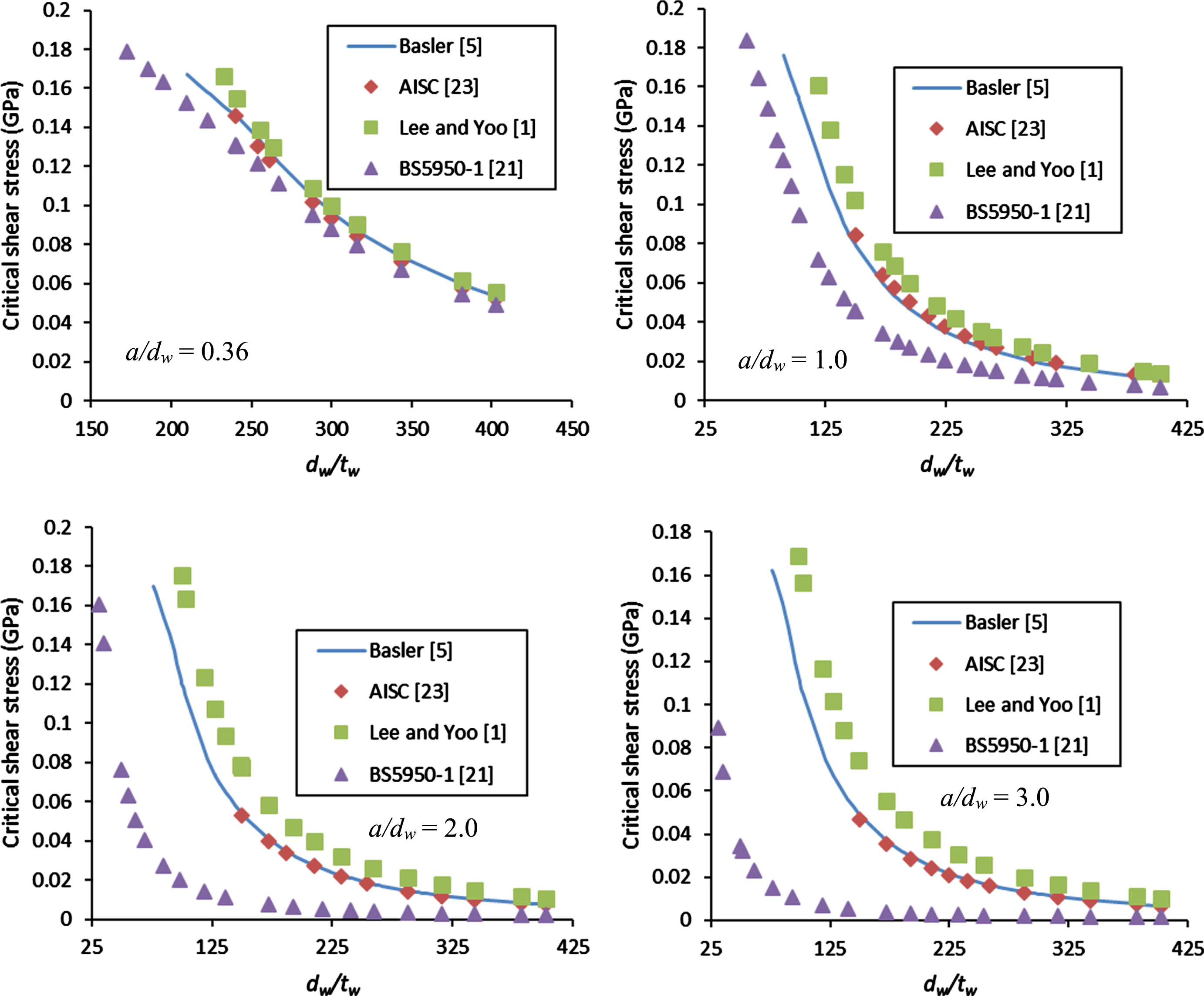
Comparison of critical shear stress estimated by analytical models.
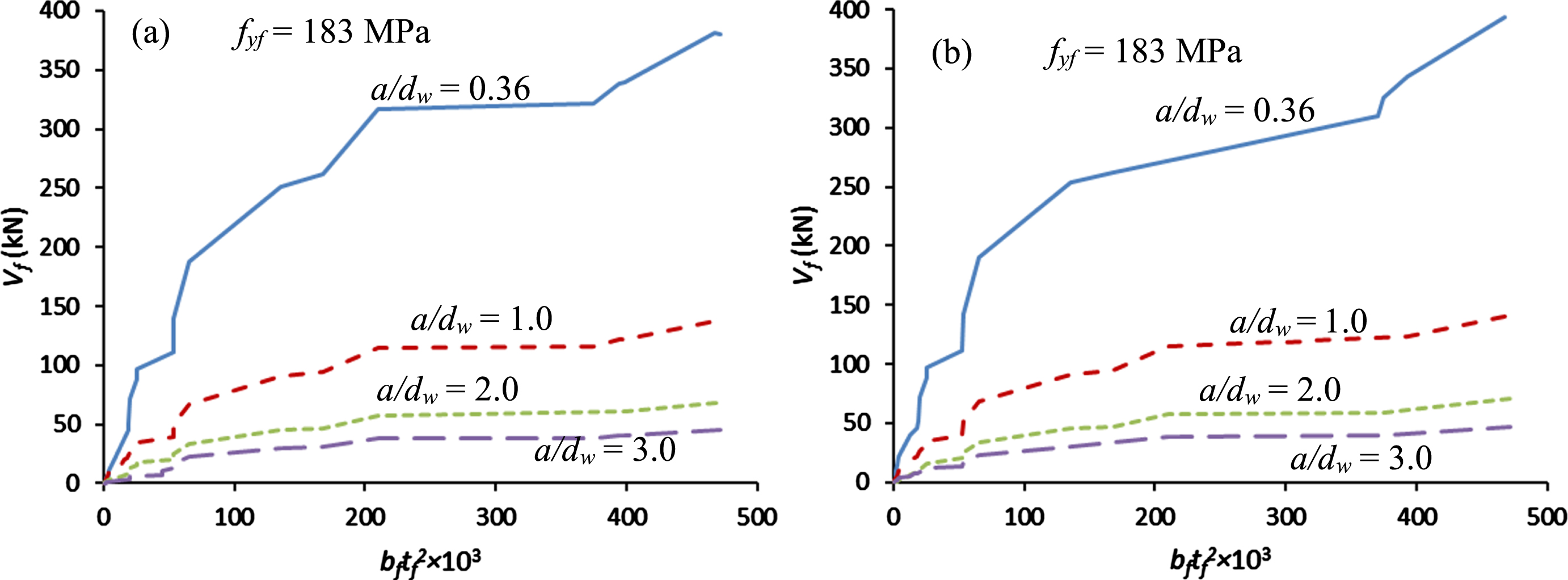
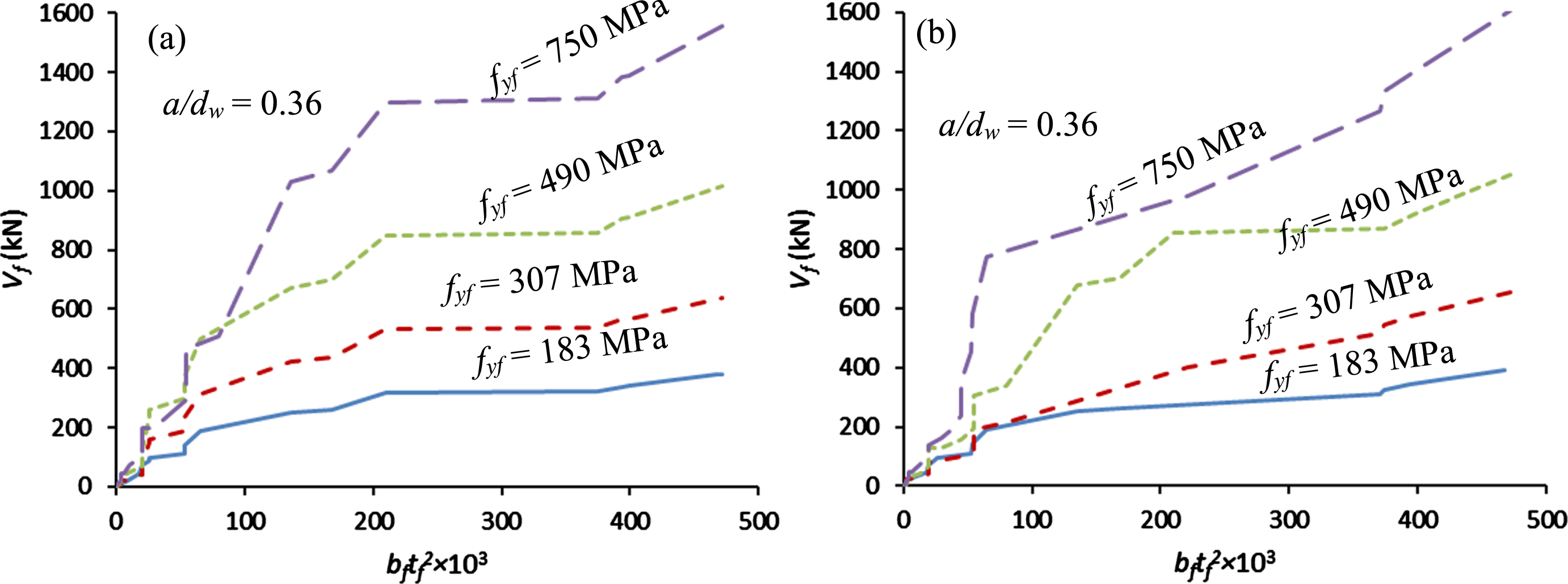
As noted before, only the analytical models recommended by BS5950-1 [21] and EC3 [22] explicitly consider the influence of flanges in providing shear resistance in the post-buckling stage. The effects of a/d w and f yf on V f of plate girders were studied by plotting V f versus b f t f 2 in Figs. 7 and 8, respectively, for both of these methods. The behaviours of both models in Figs. 7 and 8 signify that these are similar. It is seen in Fig. 7 that V f decreases with an increase in a/d w . The decrease is higher as a/d w is increased from 0.36 to 1 whereas it becomes negligible at a/d w values of 2 and 3. On the other hand, V f increases with f yf (Fig. 8) although the differences are small at low values of b f t f 2. The trends of data seen in Figs. 7 and 8 are the same for the remaining f yf and a/d w .
To parametrically investigate the differences in the estimation of V u by the employed analytical models, 27 experimentally tested girders reported in the literature (Table A1) were randomly selected with a wide range of d w /t w . The geometric properties of these girders are given in Table 4. Different combinations of a/d w and f yw (f yf is taken the same as f yw ) were used with the cross-sectional dimensions of the girders in Table 4 to determine V u . Figure 9 illustrates the variations in V u estimated by the employed analytical models at different a/d w and f yw values. All analytical models provide similar estimations of V u at a/d w = 0.36 and f yf = 183 MPa. As f yw and/or a/d w are increased, the methods proposed by Rockey and Skaloud [9] and BS5400-3 [34] predicted smaller V u for girders with d w /t w greater than 150. On the other hand, the estimated V u from the method proposed by Lee and Yoo [1] is higher when compared to other analytical models for plate girders with low d w /t w and high a/d w . This behaviour is partly a result of higher estimates of V cr by this method (Table 2).
Selected girders for parametric study
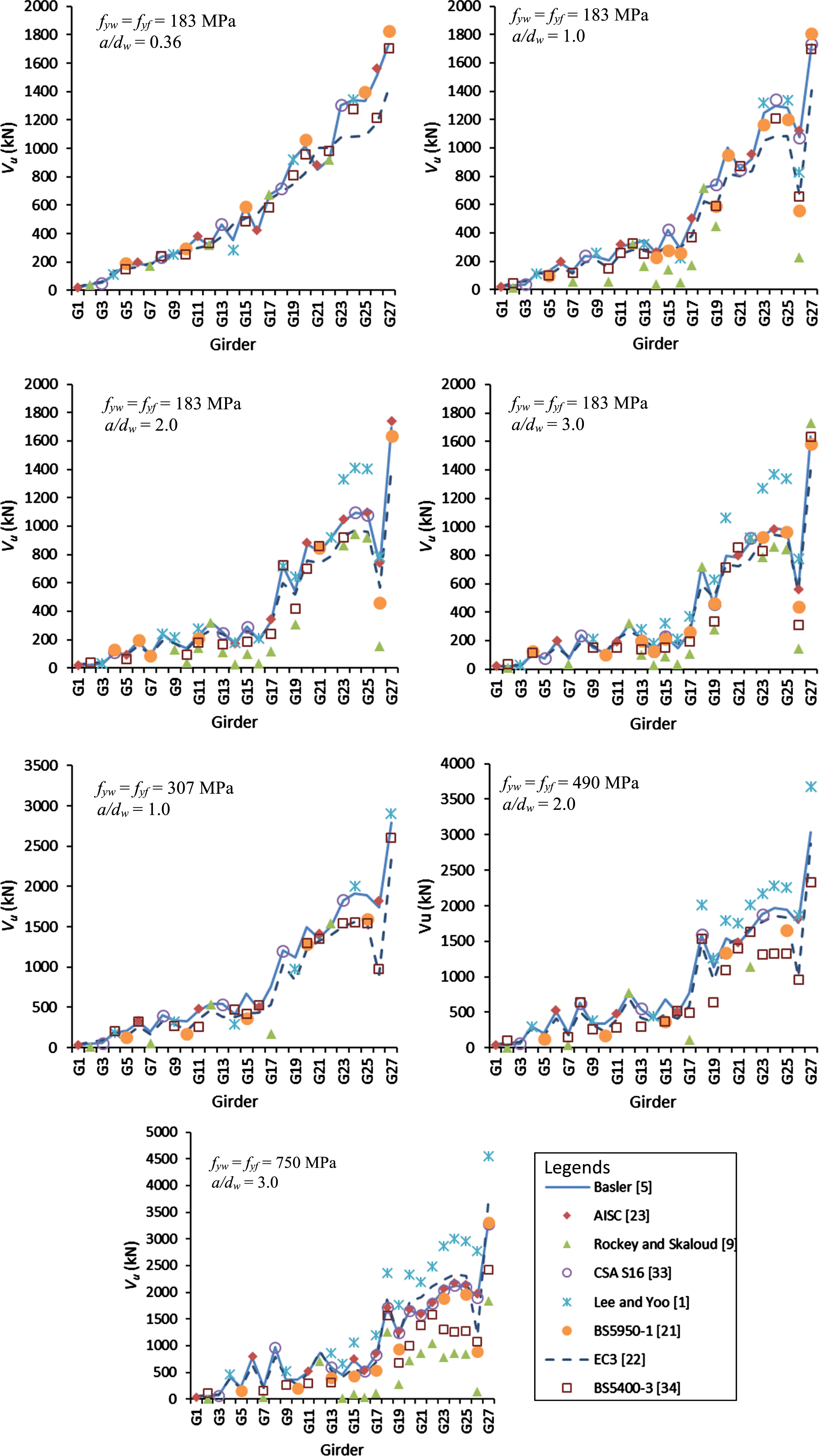
Estimated ultimate shear strength of selected girders.
Plate girders are fundamentally flexural members [34] that can be used for bridge spans up to 120 m [36]. The use of thin webs in these girders results in elastic shear buckling before the girders reach their yield capacity in bending. As a result, the design of these plate girders is controlled by their shear capacity. The results of the parametric study presented in the previous sections can be used to provide preliminary proportioning guidelines for steel plate girders to avoid shear failure.
Figure 10 illustrates variations in threshold d w /t w (to cause web buckling for a given set of other parameters) versus f yw at different a/d w values based on the analytical model recommended by Basler [5]. It is seen in Fig. 10 that threshold d w /t w decreases with an increase in f yw and/or a/d w . These variations at a particular a/d w follow a power curve of the form given by Equation (23)
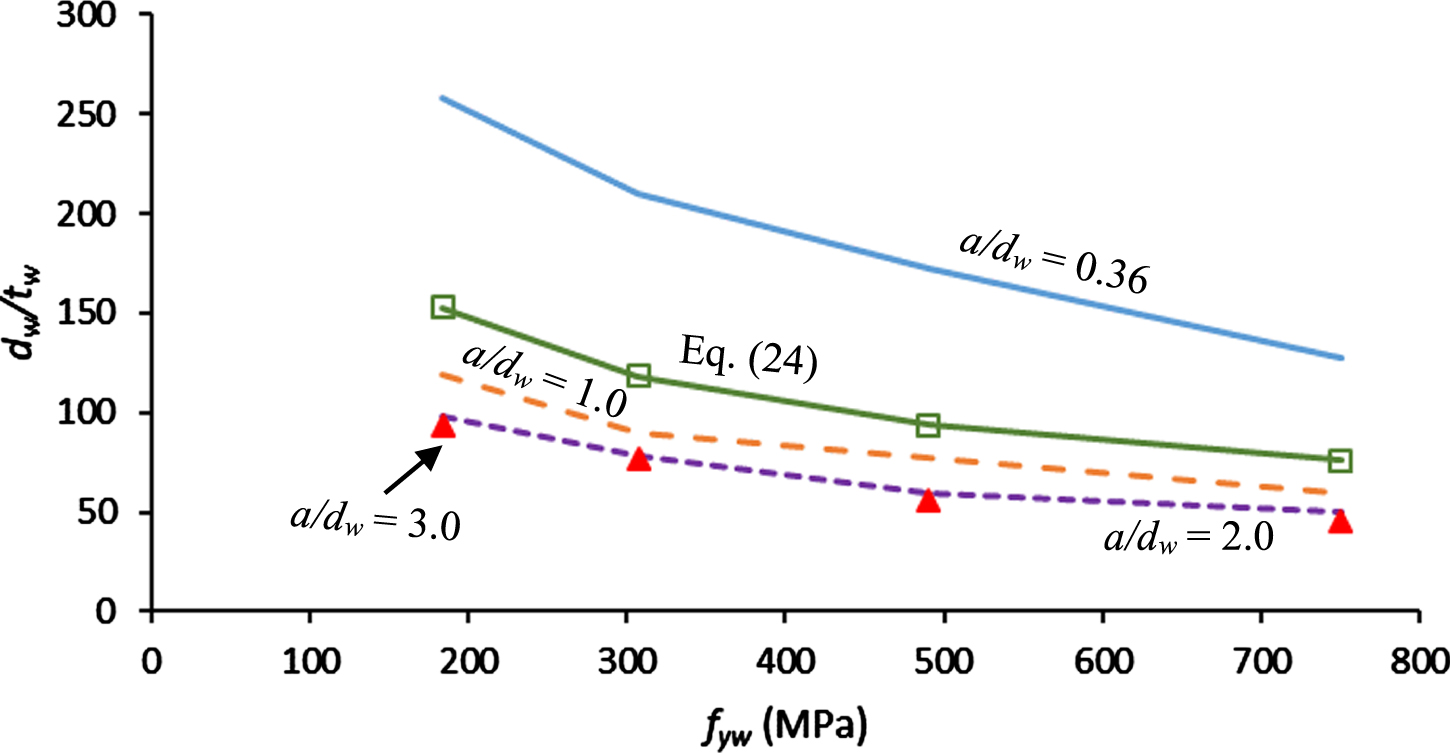
Variations in threshold slenderness ratio.
Values of factors of power curves
Figure 10 shows the curve plotted using Equation (24). Note that the limiting value of 150 for d w /t w [Equation (24)] has been recommended by AASHTO [35]. It is seen in Fig. 10 that Equation (24) complies with this requirement.
Figure 11 illustrates variations in threshold d w /t w ratios for the four f yw values used. It is seen in Fig. 11 that the curves follow a power law of the form given by Equation (23). The constants m and n were determined by carrying out regression analysis using the curve fitting method on each of the curves which are given in Table 5 as m1 and n1. The R2 values for the fitted curves were from 0.87–0.94. Using an average of factors m and n, the resulting expression is given by Equation (25)
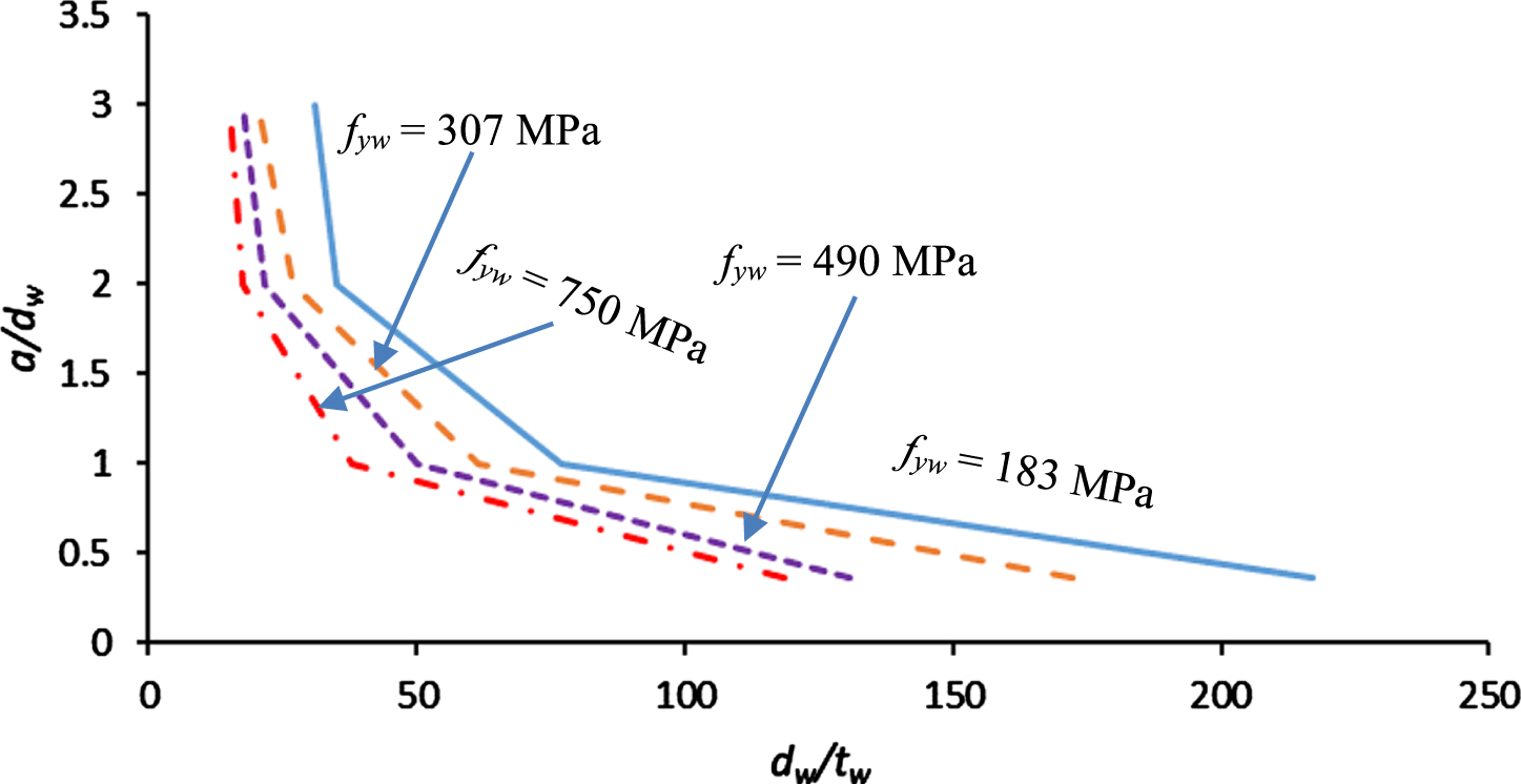
Variations in aspect ratio versus threshold slenderness ratio.
Figure 12 illustrates variations in estimated V u versus t f /t w . It is seen that V u increases nearly linearly with t f /t w to reach a maximum value at low values of t f /t w . Further, an increase in t f /t w results in a rapid decrease in V u to a small value. Thereafter, the reduction in V u is gradual until it becomes almost negligible at t f /t w = 25.
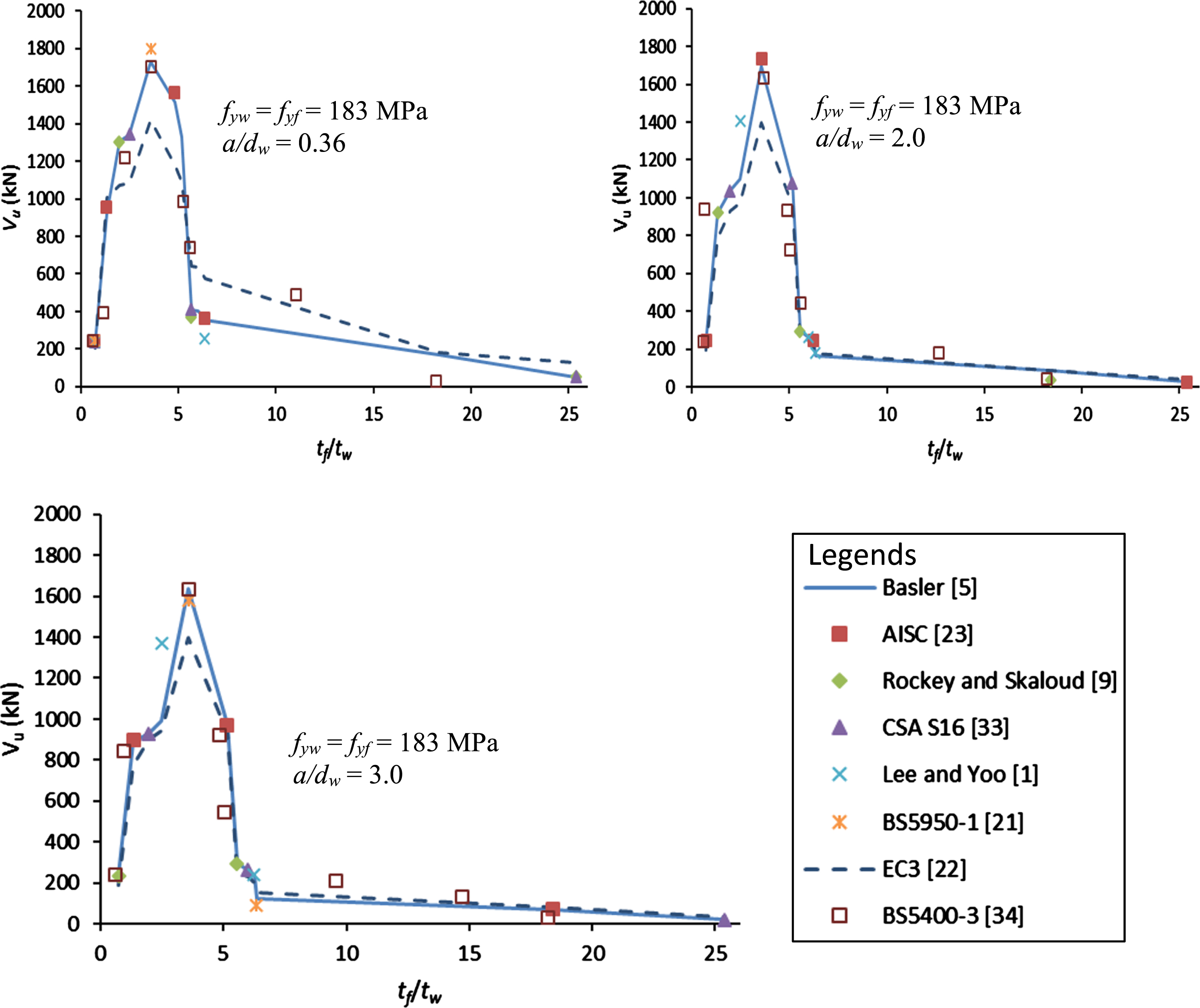
Variations of ultimate shear strength versus t f / t w .
It is noted in Figs. 12 that (despite some differences in V u estimated by the different analytical models) the maximum value of V u is reached at the same t f /t w ratio (3.59). This may be used to determine the thickness of flanges in the plate girders. Note that AASHTO [35] has a recommended minimum value of t f /t w as 1.1 which is less than 3.59.
Based on the above, the procedure for the preliminary sizing of a plate girder to avoid shear failure can be carried out using the following simple steps.
The optimum depth of the web for providing bending resistance can be determined from Equation (26) suggested by Bresler et al. [64], if this is not dictated by any other constraints (architectural, serviceability, etc.).
Using the above-calculated d w , the desired t w is calculated from Equation (24) which can be used to determine the spacing of vertical stiffeners with the help of Equation (25). The thickness of the flanges is then calculated using t f /t w = 3.6. Finally, the width of the flange can be determined from Equation (27) recommended by Kulak and Grondin [36].
Note that the minimum value of d w /6 for b f in Equation (27) has been recommended by AASHTO [35] which also suggests that b f /2t f ≤12.0.
To study the effectiveness of the proposed method for plate girder proportioning, several examples from the literature have been considered and compared. The results are summarised in Table 6. Example 10.1 [65] is an analysis problem of an existing girder whose dimensions are given in the second column of Table 6. A 14.6 m long girder was subjected to a maximum factored bending moment of 2336 kNm and a shear force of 1040 kN. The third column of Table 6 illustrates that if the same girder is to be redesigned using the above-mentioned proportioning guidelines, not only does the capacity of the girder increase both in flexure and shear, but the need for transverse stiffeners is also reduced as these are spaced at large distances which helps in overcoming fabrication and constructability issues. Although the weight of the cross-section increases slightly (10%) with the modified girder proportions, part of it can be offset by the requirement of fewer transverse stiffeners. Note that the proposed compression flange is compact and is not subjected to flange local buckling. As a result, the spacing of the transverse stiffeners is controlled by the shear design.
Data of plate girder design
Example 10.2 [65] is a design problem for an 18 m long girder that is subjected to a factored bending moment and a shear force (excluding self-weight) of 6439 kN.m and 994 kN, respectively. The cross-section of the girder determined by Segui [65] (based on trial and error calculations), and its flexure and shear capacities are given in the fourth column of Table 6. The following column of Table 6 provides the size of the plate girder based on the method developed in this paper and its capacity. It is noted that the plate girder chosen based on the proposed method is adequate and requires a lesser number of transverse stiffeners. It is also possible in this case to modify the girder by selecting a thinner web (t w = 9.5 mm) which results in the following girder dimensions and capacities: d w = 1580 mm; t w = 9.5 mm; b f = 482 mm; t f 34 mm; a = 1300 mm; weight = 3.75 kN/m; φM n =6626 kN.m; and φV n =1732 kN. As in the previous example, the proposed compression flange avoids flange local buckling and the spacing of the transverse stiffeners depends on the shear design.
It can be noted in both Examples 10.1 and 10.2 that the proposed proportioning guidelines provide thicker and narrower flanges which improve the bending resistance of plate girders. On the other hand, d w /t w values for the girders in these examples chosen by Segui [65] are larger than 150 and do not comply with the requirement of AASHTO [35]. Note that the plate girder capacities in Examples 10.1 and 10.2 are determined as suggested by AISC [23].
The third example of verifying the developed procedures is taken from section 6.7.2 of McKenzie [66]. The plate girder in this example is 12 m long and is subjected to a factored bending moment and shear force (excluding self-weight) of 5547 kN.m and 1396.2 kN, respectively. The cross-section of the plate girder, and its flexure and shear capacities as determined by McKenzie [66] are summarised in the sixth column of Table 6. The seventh column of Table 6 compares the data of the same plate girder based on the cross-section determined using the proposed procedure in this paper. Note that the flexure and shear capacities of the plate girder in the sixth and seventh columns are calculated following the procedure recommended by BS5950-1 [21]. It is noted in Table 6 that not only the proposed girder is lighter (8.6% reduction) it provides larger flexure and shear capacities as compared to the cross-section proposed by McKenzie [66]. At the same time, it requires fewer transverse stiffeners due to significantly larger spacing as compared to that found by McKenzie [66]. The flexure and shear capacities of the proposed plate girder cross section determined by using the method suggested by AISC [23] are given in the final column of Table 6 which indicate that these also meet the design requirements of this design code. In addition, the proposed girder cross sections in all three examples above satisfy all proportioning requirements suggested by AASHTO [35].
This paper investigates the shear behaviour of steel plate girders using the available analytical models in the literature. A parametric study was also carried out to understand the influence of various factors related to the design of plate girders on their shear behaviour. The following are the important conclusions drawn from the presented study: All the available analytical methods for determining critical shear strength provide conservative estimates for shear web panels with higher aspect ratios. Similarly, conservative estimates are also provided at a higher aspect ratio for the same value of the slenderness ratio. These estimates become non-conservative at high aspect and low slenderness ratios assuming the condition of two opposite simply supported and fixed edges of the web panel. The threshold value of the slenderness ratio that causes buckling in the web panel and its critical shear strength decreases as the yield strength of the web plate is increased. These, however, are not influenced significantly beyond the slenderness ratio of 200 or aspect ratio of 1. All the employed methods which consider flange contribution (either implicitly or explicitly) in the post-buckled shear capacity of the web panel provided similar estimates of the ultimate shear strength of the web panel. On the other hand, avoiding flange contribution could result in under-estimation of ultimate shear strength. The analytical models which explicitly consider the contribution of flanges to the shear capacity of web panels provide similar estimates of flange contribution. This contribution decreases with an increase in aspect ratio up to unity. Thereafter, the decrease becomes minimal. The proposed plate girder proportioning guidelines provide an effective and robust method for the optimum design of these girders. Although a wide range of variables and property datasets were used for the findings and proportioning guidelines made in this study these apply for plate girders with equal top and bottom flanges and with the same yield strength. Any future study may consider the influence of these factors on the plate girder proportioning. In addition, girders that have varying depths may also be considered for analysis in the future.
Data Availability Statement
All data, models, and code generated or used during the study appear in the submitted article.
Footnotes
Appendix
Data of experimentally tested plate girders available in literature
| Author | Girder | t w (mm) | d w (mm) | b f (mm) | t f (mm) | h f (mm) | a (mm) | b (mm) | f yw (MPa) | f yf (MPa) |
| Lyse and Godfrey [38] | WB-1 | 6.35 | 355.60 | 254.00 | 39.37 | 394.97 | 938.79 | 938.79 | 299 | 228 |
| WB-2 | 6.35 | 355.60 | 254.00 | 39.62 | 395.22 | 938.79 | 938.79 | 330 | 228 | |
| WB-3 | 6.86 | 407.16 | 255.52 | 38.10 | 445.26 | 1042.34 | 1042.34 | 342 | 228 | |
| WB-6 | 6.35 | 446.02 | 254.51 | 38.35 | 484.38 | 1092.76 | 1092.76 | 228 | 228 | |
| WB-7 | 6.35 | 389.64 | 255.78 | 38.10 | 427.74 | 997.47 | 997.47 | 232 | 228 | |
| WB-8 | 6.60 | 395.22 | 255.78 | 38.35 | 433.58 | 964.35 | 964.35 | 205 | 228 | |
| WB-9 | 6.35 | 317.50 | 255.02 | 38.10 | 355.60 | 844.55 | 844.55 | 209 | 228 | |
| WB-10 | 6.35 | 317.50 | 254.25 | 38.35 | 355.85 | 873.13 | 873.13 | 209 | 228 | |
| Bergman [39] | A2 | 3.50 | 1000.00 | 330.00 | 30.00 | 1030.00 | 2000.00 | 2000.00 | 277 | 277 |
| A6 | 3.20 | 700.00 | 300.00 | 20.00 | 720.00 | 2380.00 | 2380.00 | 224 | 224 | |
| A5 | 4.00 | 700.00 | 300.00 | 20.00 | 720.00 | 2380.00 | 2380.00 | 297 | 297 | |
| Longbottom and Heyman [40] | A4 | 1.42 | 120.65 | 53.34 | 36.13 | 127.00 | 253.37 | 253.37 | 258 | 288 |
| C4 | 1.42 | 342.90 | 18.80 | 36.13 | 349.25 | 253.75 | 253.75 | 258 | 288 | |
| A1 | 1.42 | 133.35 | 33.78 | 36.13 | 139.70 | 177.36 | 177.36 | 258 | 288 | |
| A2 | 0.06 | 5.25 | 1.00 | 0.25 | 133.35 | 10.71 | 10.71 | 258 | 288 | |
| Basler et al. [41] | G2-T1 | 6.86 | 1270.00 | 309.63 | 19.53 | 1289.54 | 1905.00 | 1905.00 | 243 | 266 |
| G2-T2 | 6.86 | 1270.00 | 309.63 | 19.53 | 1289.54 | 952.50 | 952.50 | 243 | 266 | |
| G4-T1 | 3.28 | 1270.00 | 308.86 | 19.66 | 1289.66 | 1905.00 | 1905.00 | 299 | 259 | |
| G4-T2 | 3.28 | 1270.00 | 308.86 | 19.66 | 1289.66 | 952.50 | 952.50 | 299 | 259 | |
| G6-T1 | 4.90 | 1270.00 | 308.10 | 19.76 | 1289.76 | 1905.00 | 1905.00 | 253 | 261 | |
| G6-T2 | 4.90 | 1270.00 | 308.10 | 19.76 | 1289.76 | 952.50 | 952.50 | 253 | 261 | |
| G6-T3 | 4.90 | 1270.00 | 308.10 | 19.76 | 1289.76 | 635.00 | 635.00 | 253 | 261 | |
| G7-T1 | 4.98 | 1270.00 | 309.63 | 19.48 | 1289.48 | 1270.00 | 1270.00 | 253 | 259 | |
| G7-T2 | 4.98 | 1270.00 | 309.63 | 19.48 | 1289.48 | 1270.00 | 1270.00 | 253 | 259 | |
| G8-T1 | 5.00 | 1270.00 | 304.80 | 19.05 | 1289.05 | 3810.01 | 3810.01 | 263 | 285 | |
| G8-T2 | 5.00 | 1270.00 | 304.80 | 19.05 | 1289.05 | 1905.00 | 1905.00 | 263 | 285 | |
| G8-T3 | 5.00 | 1270.00 | 304.80 | 19.05 | 1289.05 | 1905.00 | 1905.00 | 263 | 285 | |
| G8-T4 | 5.00 | 1270.00 | 304.80 | 19.05 | 1289.05 | 1270.00 | 1270.00 | 263 | 285 | |
| G9-T1 | 3.33 | 1270.00 | 304.80 | 18.80 | 1288.80 | 3810.01 | 3810.01 | 307 | 288 | |
| G9-T2 | 3.33 | 1270.00 | 304.80 | 18.80 | 1288.80 | 1905.00 | 1905.00 | 307 | 288 | |
| G9-T3 | 3.33 | 1270.00 | 304.80 | 18.80 | 1288.80 | 1905.00 | 1905.00 | 307 | 288 | |
| E1-T1 | 9.70 | 1270.00 | 522.23 | 52.30 | 1322.30 | 3810.01 | 3810.01 | 288 | 216 | |
| E1-T2 | 9.70 | 1270.00 | 457.20 | 19.05 | 1289.05 | 1905.00 | 1905.00 | 288 | 216 | |
| E1-T4 | 9.70 | 1270.00 | 457.20 | 19.05 | 1289.05 | 1270.00 | 1270.00 | 288 | 216 | |
| E2-T1 | 12.88 | 1270.00 | 355.60 | 46.23 | 1316.23 | 3810.01 | 3810.01 | 241 | 234 | |
| E2-T2 | 12.88 | 1270.00 | 355.60 | 46.23 | 1316.23 | 1905.00 | 1905.00 | 241 | 234 | |
| E4-T1 | 9.96 | 1270.00 | 355.60 | 41.66 | 1311.66 | 1905.00 | 1905.00 | 276 | 228 | |
| E4-T2 | 9.96 | 1270.00 | 355.60 | 41.66 | 1311.66 | 952.50 | 952.50 | 276 | 228 | |
| E4-T3 | 9.96 | 1270.00 | 355.60 | 41.66 | 1311.66 | 635.00 | 635.00 | 276 | 228 | |
| Granholm [42] | A3 | 2.20 | 300.00 | 100.00 | 5.00 | 305.00 | 990.00 | 990.00 | 284 | 284 |
| A4 | 2.20 | 300.00 | 100.00 | 5.00 | 305.00 | 990.00 | 990.00 | 284 | 284 | |
| A5 | 2.20 | 300.00 | 100.00 | 5.00 | 305.00 | 990.00 | 990.00 | 284 | 284 | |
| A6 | 2.20 | 300.00 | 100.00 | 5.00 | 305.00 | 990.00 | 990.00 | 284 | 284 | |
| E32 | 3.10 | 580.00 | 180.00 | 9.00 | 589.00 | 1972.00 | 1972.00 | 275 | 343 | |
| E33 | 3.10 | 580.00 | 180.00 | 9.00 | 589.00 | 1972.00 | 1972.00 | 275 | 343 | |
| E42 | 3.10 | 580.00 | 200.00 | 10.00 | 590.00 | 1972.00 | 1972.00 | 275 | 343 | |
| E53 | 2.20 | 580.00 | 130.00 | 5.40 | 585.40 | 1972.00 | 1972.00 | 275 | 275 | |
| E54 | 2.20 | 580.00 | 130.00 | 5.40 | 585.40 | 1972.00 | 1972.00 | 275 | 275 | |
| C | 4.00 | 780.00 | 130.00 | 5.40 | 785.40 | 5460.00 | 5460.00 | 277 | 277 | |
| Cooper et al. [27] | H1-T1 | 9.98 | 1270.00 | 458.72 | 24.89 | 1294.89 | 3810.01 | 3810.01 | 703 | 734 |
| H1-T2 | 9.98 | 1270.00 | 458.72 | 24.89 | 1294.89 | 1905.00 | 1905.00 | 703 | 732 | |
| H2-T1 | 9.91 | 1270.00 | 446.28 | 51.16 | 1321.16 | 1270.00 | 1270.00 | 750 | 739 | |
| H2-T2 | 9.91 | 1270.00 | 446.28 | 51.16 | 1321.16 | 635.00 | 635.00 | 750 | 739 | |
| Frost and Schilling [43] | C-1 | 4.45 | 236.47 | 76.20 | 9.86 | 246.33 | 837.12 | 837.12 | 234 | 820 |
| H-1 | 7.62 | 234.44 | 76.96 | 9.96 | 244.40 | 836.96 | 836.96 | 383 | 820 | |
| T-1 | 4.55 | 234.44 | 75.18 | 9.91 | 244.35 | 836.96 | 836.96 | 745 | 807 | |
| Knoishi [44] | B | 4.50 | 1200.00 | 240.00 | 12.00 | 1212.00 | 1200.00 | 1200.00 | 490 | 490 |
| Sakai et al. [45] | G1-1 | 6.60 | 1200.00 | 250.00 | 23.00 | 1223.00 | 3600.00 | 3600.00 | 486 | 500 |
| G1-2 | 6.60 | 1200.00 | 250.00 | 36.00 | 1236.00 | 1800.00 | 1800.00 | 486 | 500 | |
| G2-1 | 6.60 | 950.00 | 250.00 | 19.00 | 969.00 | 2850.00 | 2850.00 | 486 | 520 | |
| G2-2 | 6.60 | 950.00 | 250.00 | 32.00 | 982.00 | 1425.00 | 1425.00 | 486 | 520 | |
| Dapice et al. [46] | LS1-T1 | 4.50 | 1200.00 | 355.60 | 38.10 | 1238.10 | 1200.00 | 1200.00 | 323 | 210 |
| Sakai et al. [47] | G-1 | 8.00 | 440.00 | 160.00 | 30.00 | 470.00 | 1148.40 | 1148.40 | 431 | 412 |
| G-2 | 8.00 | 440.00 | 200.00 | 30.00 | 470.00 | 1148.40 | 1148.40 | 432 | 412 | |
| G-3 | 8.00 | 560.00 | 160.00 | 30.00 | 590.00 | 1472.80 | 1472.80 | 431 | 412 | |
| G-4 | 8.00 | 560.00 | 250.00 | 30.00 | 590.00 | 1999.20 | 1999.20 | 431 | 412 | |
| G-5 | 8.00 | 560.00 | 250.00 | 30.00 | 590.00 | 1500.80 | 1500.80 | 431 | 412 | |
| G-6 | 8.00 | 560.00 | 250.00 | 30.00 | 590.00 | 700.00 | 700.00 | 431 | 412 | |
| G-7 | 8.00 | 560.00 | 250.00 | 30.00 | 590.00 | 1500.80 | 1500.80 | 431 | 412 | |
| G-9 | 8.00 | 720.00 | 250.00 | 30.00 | 750.00 | 2001.60 | 2001.60 | 431 | 412 | |
| Lew and Toprac [48] | 21020A | 3.18 | 914.40 | 203.20 | 12.70 | 927.10 | 1219.20 | 1219.20 | 248 | 689 |
| 21530A | 3.18 | 914.40 | 203.20 | 12.70 | 927.10 | 1219.20 | 1219.20 | 248 | 689 | |
| 21540A | 3.18 | 914.40 | 203.20 | 12.70 | 927.10 | 1219.20 | 1219.20 | 248 | 689 | |
| 22540A | 3.18 | 914.40 | 203.20 | 12.70 | 927.10 | 1219.20 | 1219.20 | 248 | 689 | |
| 22550A | 3.18 | 914.40 | 203.20 | 12.70 | 927.10 | 1219.20 | 1219.20 | 248 | 689 | |
| 21020B | 3.18 | 914.40 | 203.20 | 12.70 | 927.10 | 914.40 | 914.40 | 248 | 689 | |
| 21530B | 3.18 | 914.40 | 203.20 | 12.70 | 927.10 | 914.40 | 914.40 | 248 | 689 | |
| 21540B | 3.18 | 914.40 | 203.20 | 12.70 | 927.10 | 914.40 | 914.40 | 248 | 689 | |
| 22540B | 3.18 | 914.40 | 203.20 | 12.70 | 927.10 | 914.40 | 914.40 | 248 | 689 | |
| 22550B | 3.18 | 914.40 | 203.20 | 12.70 | 927.10 | 914.40 | 914.40 | 248 | 689 | |
| 31020B | 4.76 | 914.40 | 203.20 | 12.70 | 927.10 | 914.40 | 914.40 | 248 | 689 | |
| 31530B | 4.76 | 914.40 | 203.20 | 12.70 | 927.10 | 914.40 | 914.40 | 248 | 689 | |
| 31540B | 4.76 | 914.40 | 203.20 | 12.70 | 927.10 | 914.40 | 914.40 | 248 | 689 | |
| 32540B | 4.76 | 914.40 | 203.20 | 12.70 | 927.10 | 914.40 | 914.40 | 248 | 689 | |
| 32550B | 4.76 | 914.40 | 203.20 | 12.70 | 927.10 | 914.40 | 914.40 | 248 | 689 | |
| 41020A | 6.35 | 914.40 | 203.20 | 12.70 | 927.10 | 1219.20 | 1219.20 | 248 | 689 | |
| 41530A | 6.35 | 914.40 | 203.20 | 12.70 | 927.10 | 1219.20 | 1219.20 | 248 | 689 | |
| 41540A | 6.35 | 914.40 | 203.20 | 12.70 | 927.10 | 1219.20 | 1219.20 | 248 | 689 | |
| 42540A | 6.35 | 914.40 | 203.20 | 12.70 | 927.10 | 1219.20 | 1219.20 | 248 | 689 | |
| 42550A | 6.35 | 914.40 | 203.20 | 12.70 | 927.10 | 1219.20 | 1219.20 | 248 | 689 | |
| 41530B | 6.35 | 914.40 | 203.20 | 12.70 | 927.10 | 914.40 | 914.40 | 248 | 689 | |
| 41540B | 6.35 | 914.40 | 203.20 | 12.70 | 927.10 | 914.40 | 914.40 | 248 | 689 | |
| 42540B | 6.35 | 914.40 | 203.20 | 12.70 | 927.10 | 914.40 | 914.40 | 248 | 689 | |
| 42550B | 9.53 | 914.40 | 203.20 | 12.70 | 927.10 | 914.40 | 914.40 | 248 | 689 | |
| 61530A | 9.53 | 914.40 | 203.20 | 12.70 | 927.10 | 1219.20 | 1219.20 | 248 | 689 | |
| 61540A | 9.53 | 914.40 | 203.20 | 12.70 | 927.10 | 1219.20 | 1219.20 | 248 | 689 | |
| 62540A | 9.53 | 914.40 | 203.20 | 12.70 | 927.10 | 1219.20 | 1219.20 | 248 | 689 | |
| 62550A | 9.53 | 914.40 | 203.20 | 12.70 | 927.10 | 1219.20 | 1219.20 | 248 | 689 | |
| Carskaddan [49] | C-AC2 | 3.18 | 454.15 | 93.73 | 9.73 | 463.88 | 2516.01 | 2516.01 | 211 | 754 |
| C-AC3 | 6.45 | 455.42 | 139.95 | 13.00 | 468.43 | 2513.93 | 2513.93 | 252 | 745 | |
| C-AC4 | 4.45 | 455.42 | 133.86 | 16.23 | 471.65 | 2513.93 | 2513.93 | 232 | 780 | |
| C-AC5 | 4.42 | 456.18 | 131.57 | 19.02 | 475.21 | 2518.14 | 2518.14 | 232 | 783 | |
| C-AH1 | 6.63 | 456.18 | 211.73 | 25.40 | 481.58 | 2513.58 | 2513.58 | 336 | 730 | |
| Nishino and Okumura [32] | G1 | 9.10 | 543.00 | 301.00 | 22.40 | 565.40 | 1449.81 | 1449.81 | 373 | 431 |
| G2 | 9.10 | 543.00 | 220.00 | 22.40 | 565.40 | 1449.81 | 1449.81 | 373 | 431 | |
| G3 | 9.40 | 722.00 | 302.00 | 22.20 | 744.20 | 1898.86 | 1898.86 | 373 | 431 | |
| G4 | 9.20 | 720.00 | 243.00 | 22.10 | 742.10 | 1893.60 | 1893.60 | 373 | 431 | |
| G5 | 9.00 | 899.00 | 291.00 | 22.30 | 921.30 | 2355.38 | 2355.38 | 373 | 431 | |
| G6 | 8.90 | 900.00 | 212.00 | 22.30 | 922.30 | 2358.00 | 2358.00 | 373 | 431 | |
| G7 | 9.10 | 1080.00 | 282.00 | 22.40 | 1102.40 | 2851.20 | 2851.20 | 373 | 431 | |
| G8 | 8.90 | 1080.00 | 221.00 | 22.20 | 1102.20 | 2851.20 | 2851.20 | 373 | 431 | |
| G9 | 9.10 | 1080.00 | 282.00 | 22.40 | 1102.40 | 2851.20 | 2851.20 | 373 | 431 | |
| B | 4.50 | 1200.00 | 240.00 | 12.00 | 1212.00 | 1200.00 | 1200.00 | 490 | 490 | |
| G1-1 | 6.60 | 1200.00 | 250.00 | 23.00 | 1223.00 | 3600.00 | 3600.00 | 486 | 500 | |
| G1-2 | 6.60 | 1200.00 | 250.00 | 23.00 | 1223.00 | 1800.00 | 1800.00 | 486 | 500 | |
| G2-1 | 6.60 | 950.00 | 250.00 | 19.00 | 969.00 | 2850.00 | 2850.00 | 486 | 520 | |
| G2-2 | 6.60 | 950.00 | 250.00 | 19.00 | 969.00 | 1425.00 | 1425.00 | 486 | 520 | |
| Bergfelt and Hovik [50] | G1-1 | 2.00 | 600.00 | 175.00 | 6.00 | 606.00 | 7320.00 | 7320.00 | 339 | 284 |
| G2-1 | 2.00 | 600.00 | 175.00 | 6.00 | 606.00 | 7320.00 | 7320.00 | 275 | 226 | |
| G2-2 | 2.00 | 600.00 | 175.00 | 6.00 | 606.00 | 1464.00 | 1464.00 | 275 | 226 | |
| G3-1 | 3.00 | 590.00 | 200.00 | 8.00 | 598.00 | 9800.00 | 9800.00 | 275 | 226 | |
| G3-2 | 3.00 | 590.00 | 200.00 | 8.00 | 598.00 | 9800.00 | 9800.00 | 275 | 226 | |
| G3-3 | 3.00 | 590.00 | 200.00 | 8.00 | 598.00 | 9800.00 | 9800.00 | 275 | 226 | |
| G3-4 | 3.00 | 590.00 | 200.00 | 8.00 | 598.00 | 9800.00 | 9800.00 | 275 | 226 | |
| G3-5 | 3.00 | 590.00 | 200.00 | 8.00 | 598.00 | 9800.00 | 9800.00 | 275 | 226 | |
| G3-6 | 3.00 | 590.00 | 200.00 | 8.00 | 598.00 | 9800.00 | 9800.00 | 275 | 226 | |
| G3-7 | 3.00 | 590.00 | 200.00 | 8.00 | 598.00 | 2000.00 | 2000.00 | 275 | 226 | |
| G4-1 | 3.00 | 590.00 | 200.00 | 8.00 | 598.00 | 9800.00 | 9800.00 | 275 | 226 | |
| G4-2 | 3.00 | 590.00 | 200.00 | 8.00 | 598.00 | 9800.00 | 9800.00 | 275 | 226 | |
| G4-3 | 3.00 | 590.00 | 200.00 | 8.00 | 598.00 | 9800.00 | 9800.00 | 275 | 226 | |
| G4-4 | 3.00 | 590.00 | 200.00 | 8.00 | 598.00 | 9800.00 | 9800.00 | 275 | 226 | |
| G4-5 | 3.00 | 590.00 | 200.00 | 8.00 | 598.00 | 2000.00 | 2000.00 | 275 | 226 | |
| G4-6 | 3.00 | 590.00 | 200.00 | 8.00 | 598.00 | 2000.00 | 2000.00 | 275 | 226 | |
| G4-7 | 3.00 | 590.00 | 200.00 | 8.00 | 598.00 | 9800.00 | 9800.00 | 275 | 226 | |
| G4-8 | 3.00 | 590.00 | 200.00 | 8.00 | 598.00 | 9800.00 | 9800.00 | 275 | 226 | |
| G4-9 | 3.00 | 590.00 | 200.00 | 8.00 | 598.00 | 9800.00 | 9800.00 | 275 | 226 | |
| G4-10 | 3.00 | 590.00 | 200.00 | 8.00 | 598.00 | 9800.00 | 9800.00 | 275 | 226 | |
| G4-11 | 3.00 | 590.00 | 200.00 | 8.00 | 598.00 | 9800.00 | 9800.00 | 275 | 226 | |
| G4-12 | 3.00 | 590.00 | 200.00 | 8.00 | 598.00 | 9800.00 | 9800.00 | 275 | 226 | |
| G4-13 | 3.00 | 590.00 | 200.00 | 8.00 | 598.00 | 9800.00 | 9800.00 | 275 | 226 | |
| G4-14 | 3.00 | 590.00 | 200.00 | 8.00 | 598.00 | 9800.00 | 9800.00 | 275 | 226 | |
| G5-1 | 3.00 | 590.00 | 200.00 | 8.00 | 598.00 | 6980.00 | 6980.00 | 275 | 304 | |
| G5-2 | 3.00 | 590.00 | 200.00 | 8.00 | 598.00 | 6980.00 | 6980.00 | 275 | 304 | |
| G5-3 | 3.00 | 590.00 | 200.00 | 8.00 | 598.00 | 6980.00 | 6980.00 | 275 | 304 | |
| G5-4 | 3.00 | 590.00 | 200.00 | 8.00 | 598.00 | 6980.00 | 6980.00 | 275 | 304 | |
| 6 | 3.00 | 590.00 | 200.00 | 8.00 | 598.00 | 2400.00 | 2400.00 | 324 | 270 | |
| 7 | 3.00 | 590.00 | 200.00 | 8.00 | 598.00 | 2400.00 | 2400.00 | 321 | 289 | |
| 8 | 2.00 | 300.00 | 100.00 | 6.00 | 306.00 | 2400.00 | 2400.00 | 226 | 226 | |
| 9 | 2.00 | 300.00 | 100.00 | 6.00 | 306.00 | 2400.00 | 2400.00 | 226 | 226 | |
| 10 | 2.00 | 400.00 | 100.00 | 8.00 | 408.00 | 2400.00 | 2400.00 | 226 | 226 | |
| 11 | 2.00 | 400.00 | 100.00 | 8.00 | 408.00 | 2400.00 | 2400.00 | 226 | 226 | |
| 12 | 2.00 | 500.00 | 100.00 | 10.00 | 510.00 | 2400.00 | 2400.00 | 226 | 226 | |
| 13 | 2.00 | 500.00 | 100.00 | 10.00 | 510.00 | 2400.00 | 2400.00 | 226 | 226 | |
| 14 | 2.00 | 600.00 | 100.00 | 12.00 | 612.00 | 2900.00 | 2900.00 | 226 | 226 | |
| 15 | 2.00 | 600.00 | 100.00 | 12.00 | 612.00 | 2900.00 | 2900.00 | 226 | 226 | |
| 16 | 2.00 | 700.00 | 100.00 | 15.00 | 715.00 | 3500.00 | 3500.00 | 226 | 226 | |
| 17 | 2.00 | 700.00 | 100.00 | 15.00 | 715.00 | 3500.00 | 3500.00 | 226 | 226 | |
| Rockey and Skaloud [51] | TG1 | 2.72 | 609.60 | 101.60 | 4.70 | 614.30 | 609.60 | 609.60 | 253 | 253 |
| TG1a | 2.72 | 609.60 | 101.60 | 4.75 | 614.35 | 609.60 | 609.60 | 239 | 239 | |
| TG2 | 2.72 | 609.60 | 101.60 | 6.55 | 616.15 | 609.60 | 609.60 | 238 | 238 | |
| TG2a | 2.72 | 609.60 | 101.60 | 6.43 | 616.03 | 609.60 | 609.60 | 243 | 243 | |
| TG3 | 2.74 | 609.60 | 101.60 | 12.57 | 622.17 | 609.60 | 609.60 | 252 | 252 | |
| TG3a | 2.74 | 609.60 | 101.60 | 12.62 | 622.22 | 609.60 | 609.60 | 233 | 233 | |
| TG4 | 2.72 | 609.60 | 101.60 | 15.88 | 625.48 | 609.60 | 609.60 | 229 | 229 | |
| TG4a | 2.72 | 609.60 | 101.60 | 15.82 | 625.42 | 609.60 | 609.60 | 259 | 259 | |
| TG13 | 2.62 | 609.60 | 101.60 | 25.32 | 634.92 | 609.60 | 609.60 | 271 | 271 | |
| TG5 | 2.62 | 609.60 | 203.20 | 9.50 | 619.10 | 914.40 | 914.40 | 291 | 291 | |
| TG5a | 2.62 | 609.60 | 203.20 | 9.52 | 619.12 | 914.40 | 914.40 | 263 | 263 | |
| TG6 | 2.62 | 609.60 | 203.20 | 16.36 | 625.96 | 914.40 | 914.40 | 298 | 298 | |
| TG6a | 2.62 | 609.60 | 203.20 | 16.13 | 625.73 | 914.40 | 914.40 | 252 | 252 | |
| TG7 | 2.62 | 609.60 | 203.20 | 25.91 | 635.51 | 914.40 | 914.40 | 287 | 287 | |
| TG7a | 2.62 | 609.60 | 203.20 | 25.83 | 635.43 | 914.40 | 914.40 | 293 | 293 | |
| TG8 | 2.62 | 609.60 | 203.20 | 31.98 | 641.58 | 914.40 | 914.40 | 297 | 297 | |
| TG8a | 2.62 | 609.60 | 203.20 | 28.72 | 638.32 | 914.40 | 914.40 | 297 | 297 | |
| TG9 | 2.62 | 609.60 | 203.20 | 9.85 | 619.45 | 1219.20 | 1219.20 | 266 | 266 | |
| TG9a | 2.62 | 609.60 | 203.20 | 9.85 | 619.45 | 1219.20 | 1219.20 | 289 | 289 | |
| TG10 | 2.62 | 609.60 | 203.20 | 16.26 | 625.86 | 1219.20 | 1219.20 | 266 | 266 | |
| TG11 | 2.62 | 609.60 | 203.20 | 32.13 | 641.73 | 1219.20 | 1219.20 | 295 | 295 | |
| TG12 | 2.62 | 609.60 | 203.20 | 47.98 | 657.58 | 1219.20 | 1219.20 | 264 | 264 | |
| TG12a | 2.62 | 609.60 | 203.20 | 48.20 | 657.80 | 1219.20 | 1219.20 | 275 | 275 | |
| TG14 | 0.97 | 304.80 | 76.20 | 3.12 | 307.92 | 304.80 | 609.60 | 300 | 300 | |
| TG15 | 0.97 | 304.80 | 76.20 | 5.00 | 309.80 | 304.80 | 609.60 | 300 | 300 | |
| TG16 | 0.97 | 304.80 | 76.20 | 6.45 | 311.25 | 304.80 | 609.60 | 300 | 300 | |
| TG17 | 0.97 | 304.80 | 76.20 | 9.32 | 314.12 | 304.80 | 609.60 | 300 | 300 | |
| TG18 | 0.97 | 304.80 | 76.20 | 12.95 | 317.75 | 304.80 | 609.60 | 300 | 300 | |
| TG19 | 0.97 | 304.80 | 76.20 | 15.52 | 320.32 | 304.80 | 609.60 | 300 | 300 | |
| TG20 | 2.03 | 304.80 | 76.20 | 3.25 | 308.05 | 304.80 | 609.60 | 300 | 300 | |
| TG21 | 2.03 | 304.80 | 76.20 | 4.88 | 309.68 | 304.80 | 609.60 | 300 | 300 | |
| TG22 | 2.03 | 304.80 | 76.20 | 6.48 | 311.28 | 304.80 | 609.60 | 300 | 300 | |
| TG23 | 2.03 | 304.80 | 76.20 | 9.22 | 314.02 | 304.80 | 609.60 | 300 | 300 | |
| TG24 | 2.03 | 304.80 | 76.20 | 12.95 | 317.75 | 304.80 | 609.60 | 300 | 300 | |
| TG25 | 2.03 | 304.80 | 76.20 | 15.54 | 320.34 | 304.80 | 609.60 | 300 | 300 | |
| Dimitri and Ostapenko [52] | UG1.1 | 3.05 | 914.40 | 203.20 | 15.88 | 930.28 | 731.52 | 731.52 | 299 | 236 |
| UG1.2 | 3.05 | 914.40 | 203.20 | 15.88 | 930.28 | 731.52 | 731.52 | 299 | 236 | |
| UG2.1 | 3.10 | 914.40 | 203.20 | 15.88 | 930.28 | 1097.28 | 1097.28 | 299 | 246 | |
| UG2.2 | 3.10 | 914.40 | 203.20 | 15.88 | 930.28 | 1097.28 | 1097.28 | 299 | 246 | |
| UG2.3 | 3.10 | 914.40 | 203.20 | 15.88 | 930.28 | 1097.28 | 1097.28 | 299 | 246 | |
| UG3.1 | 3.10 | 914.40 | 203.20 | 15.88 | 930.28 | 1463.04 | 1463.04 | 300 | 246 | |
| UG3.2 | 3.10 | 914.40 | 203.20 | 15.88 | 930.28 | 1463.04 | 1463.04 | 300 | 246 | |
| UG3.3 | 3.10 | 914.40 | 203.20 | 15.88 | 930.28 | 1463.04 | 1463.04 | 300 | 246 | |
| Schueller and Ostapenko [53] | UG4.1 | 3.02 | 1216.66 | 254.00 | 19.20 | 1235.86 | 2153.49 | 2153.49 | 383 | 235 |
| UG4.2 | 3.02 | 1216.66 | 254.00 | 19.20 | 1235.86 | 1751.99 | 1751.99 | 387 | 235 | |
| UG4.3 | 3.02 | 1216.66 | 254.00 | 19.20 | 1235.86 | 1776.32 | 1776.32 | 387 | 235 | |
| UG4.4 | 4.62 | 1193.80 | 254.00 | 19.20 | 1213.00 | 2113.03 | 2113.03 | 252 | 235 | |
| UG4.5 | 4.62 | 1193.80 | 254.00 | 19.20 | 1213.00 | 990.85 | 990.85 | 252 | 235 | |
| UG4.6 | 4.62 | 1219.20 | 254.00 | 19.20 | 1238.40 | 2157.98 | 2157.98 | 252 | 235 | |
| Patterson et al. [54] | F-10/1 | 6.53 | 1270.00 | 407.67 | 25.32 | 1295.33 | 1905.00 | 1905.00 | 267 | 199 |
| F-10/2 | 6.53 | 1270.00 | 407.67 | 25.32 | 1295.33 | 1524.00 | 1524.00 | 267 | 199 | |
| F-10/3 | 6.53 | 1270.00 | 407.67 | 25.32 | 1295.33 | 1524.00 | 1524.00 | 267 | 199 | |
| F-10/4 | 6.53 | 1270.00 | 407.67 | 25.32 | 1295.33 | 1905.00 | 1905.00 | 267 | 199 | |
| F-10/5 | 6.53 | 1270.00 | 407.67 | 25.32 | 1295.33 | 1524.00 | 1524.00 | 267 | 199 | |
| F-11/1 | 6.65 | 2286.00 | 359.66 | 32.00 | 2318.01 | 3429.01 | 3429.01 | 236 | 188 | |
| F-11/2 | 6.65 | 2286.00 | 359.66 | 32.00 | 2318.01 | 2743.21 | 2743.21 | 236 | 188 | |
| F-11/3 | 6.65 | 2286.00 | 359.66 | 32.00 | 2318.01 | 2286.00 | 2286.00 | 236 | 188 | |
| Skaloud [55] | TG1 | 2.50 | 1000.00 | 160.00 | 5.17 | 1005.17 | 1000.00 | 609.60 | 200 | 280 |
| TG1a | 2.50 | 1000.00 | 160.00 | 5.17 | 1005.17 | 1000.00 | 609.60 | 200 | 280 | |
| TG2 | 2.50 | 1000.00 | 200.00 | 10.10 | 1010.10 | 1000.00 | 609.60 | 200 | 280 | |
| TG2a | 2.50 | 1000.00 | 200.00 | 10.10 | 1010.10 | 1000.00 | 609.60 | 200 | 280 | |
| TG3 | 2.50 | 1000.00 | 200.00 | 16.46 | 1016.46 | 1000.00 | 609.60 | 200 | 280 | |
| TG3a | 2.50 | 1000.00 | 200.00 | 16.46 | 1016.46 | 1000.00 | 609.60 | 200 | 280 | |
| TG4 | 2.50 | 1000.00 | 200.00 | 20.16 | 1020.16 | 1000.00 | 609.60 | 200 | 280 | |
| TG4a | 2.50 | 1000.00 | 200.00 | 20.16 | 1020.16 | 1000.00 | 609.60 | 200 | 280 | |
| TG5 | 2.50 | 1000.00 | 250.00 | 29.71 | 1029.71 | 1000.00 | 914.40 | 200 | 280 | |
| TG5a | 2.50 | 1000.00 | 250.00 | 29.71 | 1029.71 | 1000.00 | 914.40 | 200 | 280 | |
| Hoglund [56] | B1 | 2.86 | 600.00 | 226.00 | 9.90 | 609.90 | 9000.00 | 9000.00 | 410 | 289 |
| B4 | 2.00 | 600.00 | 151.00 | 6.10 | 606.10 | 9000.00 | 9000.00 | 275 | 298 | |
| K1 | 2.86 | 600.00 | 226.00 | 9.90 | 609.90 | 6000.00 | 6000.00 | 410 | 288 | |
| Fujii [57] | S-1 | 3.20 | 160.00 | 100.00 | 10.40 | 170.40 | 579.20 | 579.20 | 335 | 272 |
| S-2 | 3.20 | 319.00 | 100.00 | 10.50 | 329.50 | 580.58 | 580.58 | 352 | 273 | |
| S-3 | 3.20 | 477.00 | 101.00 | 10.50 | 487.50 | 577.17 | 577.17 | 317 | 272 | |
| Bergfelt [58] | G1-1 | 2.00 | 600.00 | 160.00 | 5.50 | 605.50 | 7200.00 | 7200.00 | 339 | 284 |
| G2-2 | 2.00 | 600.00 | 160.00 | 5.50 | 605.50 | 1440.00 | 1440.00 | 275 | 226 | |
| G3-1 | 3.00 | 590.00 | 160.00 | 5.42 | 595.42 | 10030.00 | 10030.00 | 275 | 226 | |
| G3-5 | 3.00 | 590.00 | 160.00 | 5.42 | 595.42 | 10030.00 | 10030.00 | 275 | 226 | |
| G3-6 | 3.00 | 590.00 | 200.00 | 10.08 | 600.08 | 10030.00 | 10030.00 | 275 | 226 | |
| Rockey and Skaloud [9] | RTG1 | 1.27 | 304.80 | 76.20 | 4.50 | 309.30 | 304.80 | 304.80 | 244 | 244 |
| RTG2 | 1.27 | 304.80 | 76.20 | 4.65 | 309.45 | 304.80 | 304.80 | 244 | 244 | |
| RTG3 | 0.97 | 304.80 | 76.20 | 4.65 | 309.45 | 304.80 | 304.80 | 259 | 259 | |
| RTG4 | 0.97 | 304.80 | 76.20 | 4.65 | 309.45 | 304.80 | 304.80 | 259 | 259 | |
| STG1 | 2.01 | 279.40 | 127.00 | 7.92 | 287.32 | 551.18 | 551.18 | 244 | 244 | |
| STG2 | 1.60 | 252.73 | 127.00 | 6.35 | 259.08 | 501.65 | 501.65 | 244 | 244 | |
| STG3 | 1.42 | 254.00 | 190.50 | 12.69 | 266.69 | 502.92 | 502.92 | 259 | 259 | |
| STG4 | 1.24 | 251.46 | 101.60 | 6.35 | 257.81 | 497.84 | 497.84 | 259 | 259 | |
| Skaloud and Novak [59] | PTG1 | 2.00 | 500.00 | 50.00 | 5.95 | 505.95 | 500.00 | 500.00 | 253 | 253 |
| TG1 (W1) | 2.50 | 1000.00 | 160.00 | 5.50 | 1005.50 | 1000.00 | 1000.00 | 219 | 219 | |
| Rockey [60] | MS0 | 2.00 | 608.00 | 102.00 | 10.10 | 618.10 | 948.48 | 948.48 | 183 | 189 |
| SD1 | 2.00 | 594.00 | 250.00 | 12.00 | 606.00 | 594.00 | 594.00 | 194 | 149 | |
| SD3 | 2.00 | 594.00 | 250.00 | 12.00 | 606.00 | 594.00 | 594.00 | 194 | 149 | |
| Lee and Yoo [18] | G1 | 4.00 | 400.00 | 130.00 | 15.00 | 415.00 | 400.00 | 400.00 | 319 | 304 |
| G2 | 4.00 | 600.00 | 200.00 | 10.00 | 610.00 | 600.00 | 600.00 | 319 | 304 | |
| G3 | 4.00 | 600.00 | 200.00 | 15.00 | 615.00 | 600.00 | 600.00 | 319 | 304 | |
| G4 | 4.00 | 400.00 | 130.00 | 15.00 | 415.00 | 600.00 | 600.00 | 319 | 304 | |
| G5 | 4.00 | 600.00 | 200.00 | 10.00 | 610.00 | 900.00 | 900.00 | 319 | 304 | |
| G6 | 4.00 | 600.00 | 200.00 | 20.00 | 620.00 | 900.00 | 900.00 | 319 | 304 | |
| G7 | 4.00 | 600.00 | 200.00 | 10.00 | 610.00 | 1200.00 | 1200.00 | 285 | 304 | |
| G8 | 4.00 | 600.00 | 200.00 | 15.00 | 615.00 | 1200.00 | 1200.00 | 285 | 304 | |
| G9 | 4.00 | 400.00 | 130.00 | 10.00 | 410.00 | 1200.00 | 1200.00 | 285 | 304 | |
| G10 | 4.00 | 400.00 | 130.00 | 15.00 | 415.00 | 1200.00 | 1200.00 | 285 | 304 | |
| Holmes [61] | C1 | 2.00 | 280.00 | 65.00 | 5.85 | 285.85 | 450.00 | 450.00 | 275 | 275 |
| C2 | 8.00 | 280.00 | 65.00 | 5.85 | 285.85 | 450.00 | 450.00 | 275 | 275 | |
| C3 | 2.00 | 280.00 | 65.00 | 2.00 | 282.00 | 450.00 | 450.00 | 275 | 275 | |
| C4 | 2.00 | 280.00 | 65.00 | 8.00 | 288.00 | 450.00 | 450.00 | 275 | 275 | |
| C5 | 2.00 | 280.00 | 65.00 | 5.85 | 285.85 | 100.00 | 100.00 | 275 | 275 | |
| C6 | 2.00 | 280.00 | 65.00 | 5.85 | 285.85 | 225.00 | 225.00 | 275 | 275 | |
| Kwon and Ryu [37] | S-120-120 | 4.5 | 1175.85 | 250 | 12 | 1187.85 | 435.12 | 435.12 | 339 | 377 |
| S-120-180 | 4.5 | 1175.85 | 250 | 12 | 1187.85 | 740.88 | 740.88 | 339 | 377 | |
| S-120-240 | 4.5 | 1175.85 | 250 | 12 | 1187.85 | 1034.88 | 1034.88 | 339 | 377 | |
| S-120-300 | 4.5 | 1175.85 | 250 | 12 | 1187.85 | 1340.64 | 1340.64 | 339 | 377 | |
| S-100-120 | 4.5 | 976.05 | 250 | 12 | 988.05 | 439.2 | 439.2 | 339 | 377 | |
| S-100-180 | 4.5 | 976.05 | 250 | 12 | 988.05 | 741.76 | 741.76 | 339 | 377 | |
| S-100-240 | 4.5 | 976.05 | 250 | 12 | 988.05 | 1044.32 | 1044.32 | 339 | 377 | |
| S-100-300 | 4.5 | 976.05 | 250 | 12 | 988.05 | 1337.12 | 1337.12 | 339 | 377 | |
| S-80-120 | 4.5 | 775.8 | 250 | 12 | 787.8 | 442.32 | 442.32 | 339 | 377 | |
| S-80-180 | 4.5 | 775.8 | 250 | 12 | 787.8 | 737.2 | 737.2 | 339 | 377 | |
| S-80-240 | 4.5 | 775.8 | 250 | 12 | 787.8 | 1039.84 | 1039.84 | 339 | 377 | |
| S-80-300 | 4.5 | 775.8 | 250 | 12 | 787.8 | 1342.48 | 1342.48 | 339 | 377 | |
| S-60-120 | 4.5 | 576 | 150 | 12 | 588 | 437.76 | 437.76 | 339 | 377 | |
| S-60-180 | 4.5 | 576 | 150 | 12 | 588 | 737.28 | 737.28 | 339 | 377 | |
| S-60-240 | 4.5 | 576 | 150 | 12 | 588 | 1042.56 | 1042.56 | 339 | 377 | |
| S-60-300 | 4.5 | 576 | 150 | 12 | 588 | 1342.08 | 1342.08 | 339 | 377 |