
Abstract
BACKGROUND:
There is a lack of consensus concerning the coracoid graft length in the modified Bristow procedure.
OBJECTIVE:
We attempted to determine the optimal graft length using the three-dimensional finite element method.
METHODS:
In a shoulder model with a 25% anterior glenoid defect, a coracoid graft of varying lengths (5, 10, 15, and 20 mm) was fixed using a half-threaded screw. First, a compressive load of 500 N was applied to the screw head to determine the graft failure load during screw tightening. Next, a tensile load (200 N) was applied to the graft to determine the failure load due to biceps muscle traction.
RESULTS:
In the screw compression, the failure loads in the 5-, 10-, 15-, and 20-mm models were 252, 370, 377, and 331 N, respectively. In the tensile load applied to the coracoid graft, the failure load exceeded 200 N for both the 5- and 10-mm models.
CONCLUSION:
The 5-mm graft had a high risk of fracture during intraoperative screw tightening. As for the biceps muscle traction, the 5- and 10-mm-grafts had a lower failure risk than the 15- and 20-mm-grafts. Therefore, we believe that the optimal length of the coracoid graft is 10 mm in the modified Bristow procedure.
Keywords
Introduction
The modified Bristow procedure has been recognized as one of the most reliable surgical options for traumatic anterior shoulder instability, particularly in patients with a large glenoid defect [1–3]. Although various modifications have been reported, the main concept of this procedure is to osteotomize the coracoid process with the attached conjoint tendon, which is placed onto the anterior glenoid neck in the standing position using a half-threaded metal screw. It has been reported that grafted coracoid bones contributed to the reconstruction of the glenoid cavity and that transferred conjoint tendons restrained anterior translation of the humeral head in shoulder abduction [3]. Most authors recommend that the coracoid graft must flush with the glenoid surface to avoid future arthritic changes [1,2,4,5].
Another important issue in this procedure was the length of the coracoid graft. Previous authors recommended using only the tip of the coracoid process with a graft length range of 1.0–1.5 cm from a clinical point of view [1,2,4–7]. They did not, however, explain the biomechanical or biological rationale that informed their recommendations. In clinical practice, several complications have been associated with coracoid grafts, such as intraoperative coracoid graft fracture during screw fixation, postoperative non-union of the graft, and the breakage of the inserted screw (Fig. 1a, b) [2,8–10]. These complications have implications for the mechanical failure of a grafted coracoid, which is presumably traceable to biomechanical limitations with respect to the graft length.
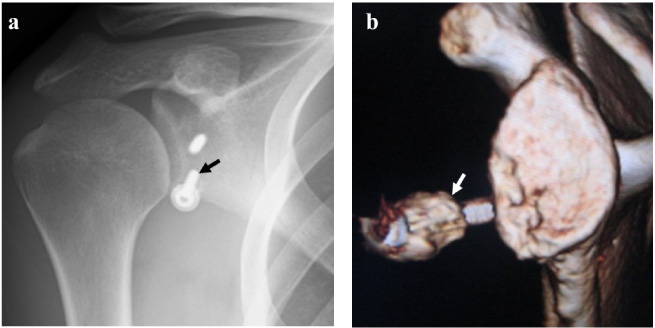
Coracoid graft complications after the modified Bristow procedure. (a) Breakage of the inserted screw (black arrow) in a 24-year-old male (antero-posterior view, plain radiograph). (b) Non-union of the coracoid graft (white arrow) with loosening of the inserted screw in a 28-year-old male (lateral view of the scapula, 3-dimensional computed tomogram).
Based on this presumption, we attempted to investigate the biomechanical role of the coracoid graft length in the modified Bristow procedure using a three-dimensional finite element (3-D FE) method. The main goal of this study was to determine the optimal length of the coracoid graft in this procedure with a view to minimizing intraoperative and postoperative complications.
This study and all its protocols were approved by the Institutional Ethical Committee (Protocol number: SENBYOSO-354).
Development of the finite element (FE) models
A 25-year-old male patient with traumatic left anterior shoulder instability was enrolled in the present study. A written informed consent was obtained prior to any study-related procedures. Computed tomographic digital imaging and communications in medicine (CT-DICOM) data of the contralateral right shoulder were imported into the Mechanical Finder software (version 11.0, Extended Edition, RCCM, Japan). The medial aspect of the scapular body, the distal part of the humerus, and the clavicle were excluded to reduce the model’s size. In a normal shoulder joint model, a 25% bony defect was created on the anterior glenoid rim. The osteotomy line was determined based on the previous biomechanical study [11,12]. Then, a 20-mm-long FE model of the coracoid process was prepared separately and saved as a stereolithography (STL) file for grafting.
Modeling of the articular cartilage
The articular cartilage layers were designed both in the glenoid and humeral head, based on findings from previous reports [13,14]. Briefly, the glenoid bone STL data were superimposed on the original model and moved 2 mm laterally to recreate a 2-mm-thick articular cartilage layer. As regards the humeral head cartilage, the humeral head bone STL data were also superimposed on the original model, which was magnified 1.05 times to recreate a 2-mm-thick articular cartilage layer around the humeral head.
Simulation of coracoid transfer
The coracoid process was superimposed on the FE model in standing position, which was placed on the anterior glenoid defect to simulate the modified Bristow procedure. We ensured that the coracoid process flushed with the glenoid cartilage during the glenoid cavity reconstruction [1,2,4,5]. In the present study, the coracoid graft was shortened by 0.5 cm to enable us to successfully create models with a 2.0-, 1.5-, 1.0-, or 0.5-cm-long coracoid graft. A half-threaded screw (diameter: 3.5 mm) was used for fixing the coracoid graft onto the glenoid neck (Fig. 2). We did not model any soft tissues (such as the capsule, labrum, glenohumeral ligament, and conjoint tendon) in this study.
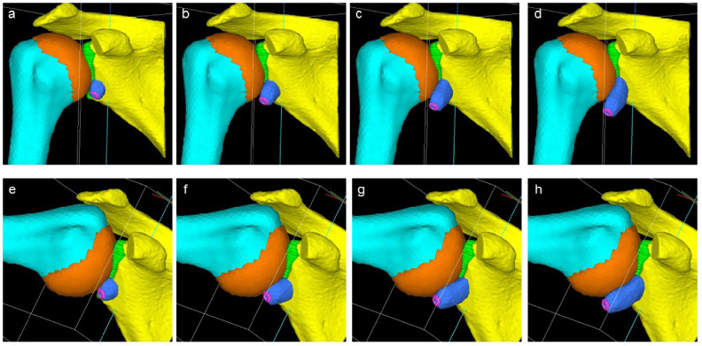
Developed FE models with different lengths of the coracoid graft (a–d: 0° abduction, e–h: 90° abduction; a and e: 5 mm, b and f: 10 mm, c and g: 15 mm, d and h: 20 mm).
To clarify the influence of arm position on the stress distribution, we attempted to simulate the shoulder joint in both 0° and 90° abductions. We hypothesized that the axis of rotation during shoulder abduction runs through the central point of the humeral head in an anteroposterior direction. The abduction angles of the scapula and humeral head were positioned at 30° and 60°, respectively, to create a FE model with the shoulder joint in a 90° abduction [13,14] (Fig. 2).
Material properties
The Young’s moduli of the humerus and scapula were calculated using CT data, based on the method proposed by Keyak et al. [15]. The Poisson’s ratio was determined according to the bone mass density, which was calculated using CT data. We set Young’s modulus and Poisson’s ratio of the articular cartilage as 35.0 MPa and 0.49, respectively, in line with those of previous reports [13,14]. In addition, the Young’s modulus and Poisson’s ratio of the half-threaded screw, which was made of titanium alloy, were extracted from the database of the software and set at 113.8 GPa and 0.30, respectively.
Contact conditions
The gap elements were inserted to recreate contact between the humeral head and glenoid cartilage, and between the humeral head and the lateral surface of the coracoid graft. Since we focused on the early postoperative period when bony union is incomplete, we also inserted gap elements between the grafted coracoid and glenoid bones [13,14].
Definition of failure
In the Mechanical Finder software, the ratio of ultimate element stress to yield stress was determined to be 0.8. We hypothesized that an element crack in tension would occur when the maximum principal stress exceeded the element ultimate tensile stress. A yield in the compression was defined when the Drucker–Prager equivalent stress exceeded the element yield stress. Element failure during compression was defined when the absolute value of the maximum principal strain exceeded a microstrain of 10,000 [16]. In the present study, the failure load was defined as a load at which a crack would occur in at least one shell element of bone in the coracoid graft.
Analyses
In the present study, following three analyses were performed with different loading conditions. The medial margin of the scapula was completely constrained in all directions to avoid movement during these analyses. However, we did not simulate the activity of each rotator cuff muscle individually in either analysis to simplify the model and shorten the calculation time.
Data interpretation
In Analyses 1 and 2, the value of the failure load was compared across the models with different lengths of coracoid graft in each arm position. In these analyses, we hoped to determine which length of the coracoid graft was the most fragile during intraoperative screw tightening as well as in the postoperative biceps muscle traction.
In Analysis 3, the distribution patterns of the maximum principal stress and Drucker–Prager equivalent stress were compared among the four models in each arm position. Next, the elements within the coracoid graft were extracted. After which, the mean values of these stresses within the coracoid graft elements were compared among the four models with the two arm positions. In this analysis, we planned to clarify the biomechanical roles of the coracoid graft length during shoulder elevation, particularly in the early postoperative period.
Results
In Analysis 1, the failure loads of the coracoid graft in the 5-, 10-, 15-, and 20-mm models were 252, 370, 377, and 331 N, respectively. The lowest failure load was seen in the 5-mm graft model among the four models (Table 1).
Failure load of the coracoid graft during screw compression
Failure load of the coracoid graft during screw compression
In Analysis 2, neither the 5- nor 10-mm coracoid graft model failed even with 200 N of tensile load for both arm positions. On the other hand, the 15-mm coracoid graft model failed at 166 N in the 90° abduction, although failure did not occur in the 0° abduction. In this analysis, failure occurred in both arm positions in the 20-mm graft model. The failure loads in this model for the 0° and 90° abductions were 38 and 108 N, respectively (Table 2).
Failure load of the coracoid graft due to biceps muscle traction
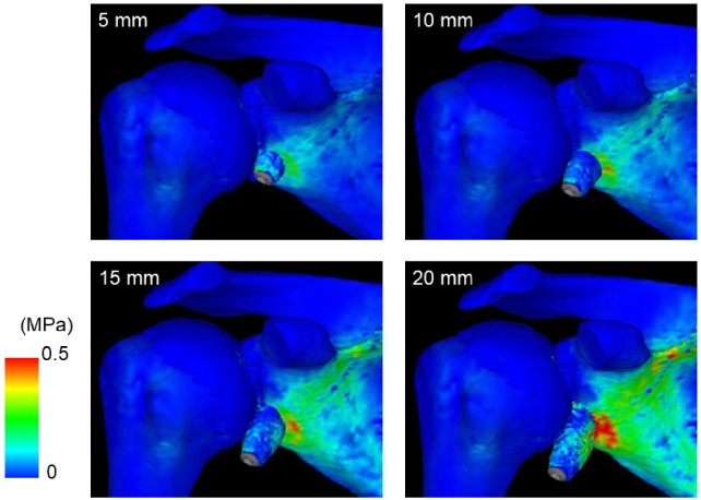
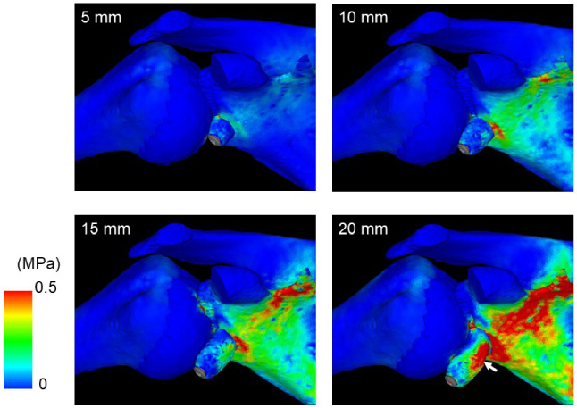
Distribution pattern of the maximum principal stress in the 0° abduction. The highest concentration is seen in the glenoid neck, particularly in the medial aspect of the coracoid graft.
In Analysis 3, both the principal stress and equivalent stress concentrations became more evident with increasing graft length (Figs 3–6). A high concentration of both stresses was seen around the contact surface between the coracoid graft and the glenoid. Such stress concentration became more evident with the increasing length of the coracoid graft. For both arm positions, the values of the maximum principal and equivalent stresses within the coracoid graft generally increased with increasing graft length (Fig. 7). The same trend was also seen in the inserted screw, where both the maximum principal and equivalent stresses increased with the increasing graft length (Fig. 8).
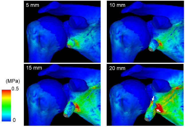
Distribution pattern of the equivalent stress in the 0° abduction. Note the 20-mm model demonstrates a high stress concentration within the coracoid graft close to the attachment to the scapula (white arrows).
Distribution pattern of the maximum principal stress in the 90° abduction. A high stress concentration appears in the medial aspect of the coracoid graft in the 20-mm model (white arrow).
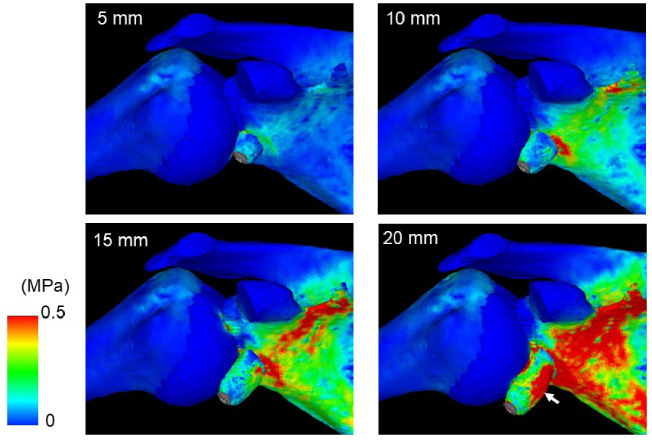
Distribution pattern of the equivalent stress in the 90° abduction. A high stress concentration appears in the medial aspect of coracoid graft in the 20-mm model (white arrow).
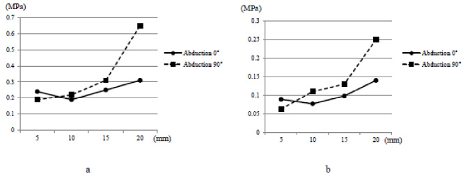
Mean values of stresses within the coracoid graft when a tensile load of 20 N was applied to the coracoid graft. For both arm positions, the values of the equivalent (a) and maximum principal (b) stresses within the coracoid graft generally increase with increasing graft length, except for the 10-mm coracoid graft model in the 0° abduction.
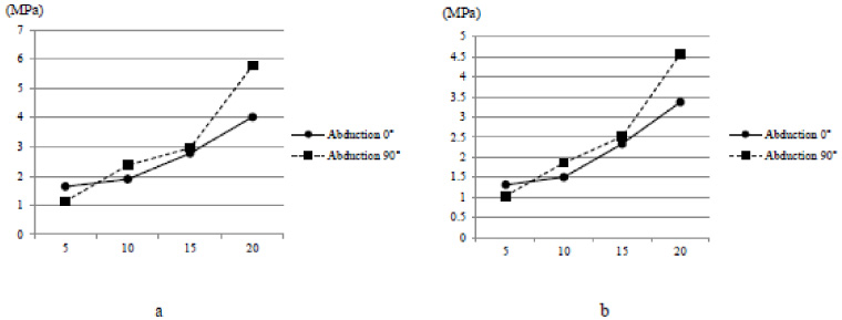
Mean values of stresses within the inserted screw when a tensile load of 20 N applied to the coracoid graft. For both arm positions, the values of the equivalent (a) and maximum principal (b) stresses within the inserted screw increase with increasing graft length.
The main focus of this study is to determine the optimal coracoid graft length in the modified Bristow procedure using the 3-D FE method in patients with traumatic anterior shoulder instability. The results of the present study clearly indicate that the 5-mm coracoid graft model demonstrated the lowest failure load among the four models with screw head compression. This could be interpreted as meaning that the 5-mm short coracoid graft might have the highest risk of fracture during the intraoperative screw tightening in clinical settings.
In the 15- and 20-mm coracoid graft models, a 200-N traction of the coracoid graft caused the graft failure. We assumed that using a long coracoid graft might increase the risk of fracture due to postoperative overtraction of the biceps muscle. These results could be explained by the unique anatomy of the coracoid process. Since the biceps muscle is attached only to the tip of the coracoid process, the length of the lever arm increased with the increase in graft length. Similarly, both maximum principal and equivalent stresses within the inserted screw increased with increasing graft length, which could be interpreted as meaning that the risk of screw breakage might also increase with increasing the graft length. Based on these results, we believed that it would be better for surgeons to use a short coracoid graft to reduce the risk of postoperative failure of the coracoid graft as well as the inserted screw.
In the stress distribution, the results of the present study clearly demonstrated that the longer the coracoid was grafted, the more enhanced the stress concentration appeared around the contact surface between the coracoid graft and the glenoid. We assume that the risks of bony resorption around the inserted screw might increase with increasing graft length since a too-high stress concentration around the screw might damage the surrounding cancellous bone.
It has been shown that the bone block effect constitutes one of the stabilizing mechanisms of the shoulder joint [3,4,12,17]. To maximize this effect, it is important to fix a certain size of the bone block at the anterior glenoid rim, particularly in the shoulders with a large bony defect. However, since both the diameter and area of the glenoid significantly increased after the modified Bristow procedure, particularly with proper bone union as reported by Tasaki et al. [1], surgeons might not necessarily need to graft a too long coracoid bone. Based on these reports and the results of the present study, we have assumed that the optimal length of the coracoid graft might be 10 mm in this procedure.
There were several limitations to this present study. First, we have developed FE models using CT-DICOM data for one normal shoulder. Second, no soft tissue was taken into consideration, which might have affected the intraarticular stress distribution. Third, three-dimensional dynamic motions were not taken into consideration in the study since we really focused on the early postoperative phase before bony union was established. Future analyses using more sophisticated FE models would be necessary to properly assess the pathomechanism of coracoid graft failure after the modified Bristow procedure.
Conclusions
Based on our findings and within the identified limitations, the optimal length of the coracoid graft was 10 mm after the modified Bristow procedure from a biomechanical perspective. While the 5-mm coracoid graft might have the highest risk of fracture during the intraoperative screw tightening, the risk of postoperative graft failure increased with increasing the graft length. These findings could be considered a guide for surgeons in clinical practice.
Footnotes
Acknowledgements
This present study was partly supported by the research grant of Non-Profit Organization Tohoku Orthopaedic Surgeons.
Ethics statement
The study was conducted in accordance with The Code of Ethics of the World Medical Association (Declaration of Helsinki).
Conflict of interest
None to report.
Disclaimer
Neither generative AI nor AI-assisted technologies were used in the writing process.