
Abstract
This paper presents an implementation of a practical and low-cost hardware-based control system for multifunctional myoelectric hand prostheses. The model utilizes a mode-switching technique in order to voluntarily control the operation of a dual-mode prosthetic device in two degrees of freedom: grasp/release and pronation/supination. This system was designed specifically to cater to the increasing needs of patients in developing countries, where myoelectric prostheses are scarce and extremely expensive. The design relied entirely on locally-available commercial components and aimed at allowing small prosthetics producers the freedom to utilize and modify the design according to their clients' preferences and requirements. Evaluation tests revealed excellent control and ability to execute basic hand and wrist functions even with short training periods, although results varied with the underlying level of muscular activity.
Introduction
Ever since the concept of myoelectric prosthetics first became a reality there has been a continuing and incremental effort aimed at maximizing the number of degrees of freedom in which the device may be operated, while simultaneously minimizing the number of electrode muscle sites required to accomplish this task.
Berger and Huppert where among the first to employ an electrical signal for the control of a myoelectric prosthesis. 1 Shortly after, in 1966, a three-state (rest, open, and close) single-site control concept was introduced by Dorcas and Scott in which each degree of freedom was controlled by a single muscle site. 2 During approximately the same period various other strategies based on multistate myoelectric control were also introduced; these systems required multiple control sites for multifunctional control. 3,4 Paciga et al. 5 and Richard et al. 6 studied the feasibility of multi-state (up to five-state) myoelectric control systems. The user error was found to significantly increase when attempting to control more than three states from a single channel.
Improvements in multifunctional myoelectric control have been proposed through the implementation of various digital signal processing algorithms both to single site, as well as electrode array-based systems. 7–9 Numerous signal classification methods have also been employed in order to map signal features to myoelectric prosthesis function. Almstrom et al. 10 reported a multifunctional myoelectric controller using a linear discriminant classifier. Other such approaches include the use of Bayes classifier, 11 “nearest neighbor” classifiers 12 and more recently, neural network classifiers, 13 time-frequency (wavelet) based representation, 14 fuzzy systems, 15 time-series models, 16 and Gaussian mixture models 17 among many others. 18–22
These efforts have resulted in an array of impressive control strategies and algorithms, many of which have yet to leave the laboratory. As for those strategies that have been adopted by major prosthetics producers and have resulted in highly functional and aesthetically pleasing myoelectric prostheses, they remain unaffordable to most amputees who usually reside in the poorest and most conflict-ridden countries. And while opportunities exist for amputees in western industrialized nations to obtain subsidized high-tech prostheses and rehabilitation, 23 such devices remain cost prohibitive for people living in third-world countries. Consequently, there is a genuine need for simple, functional, and affordable control systems for basic myoelectric prostheses that may be constructed using commercially-available and inexpensive components.
Two-site myoelectric control systems are among the most simple and robust strategies to implement. The functionality of such systems may be substantially enhanced by implementing computationally complex signal processing algorithms, as mentioned earlier. But in order to balance functionality with design simplicity and reduced cost we opted to minimize the computational requirements of the prosthesis and adopt a more primitive two-site system design utilizing a mode switching technique to enable the two-site system to control multiple functions (degrees of freedom) on the terminal device.
Materials and methods
The block diagram in Figure 1 provides an overview of the system components and the various signal processing stages implemented. The acquired EMG signal passes through an instrumentation amplifier as a pre-amplification stage, followed by a band pass filter, a full wave rectifier, a shaping amplifier with a bias adjustment stage, an averaging circuit, threshold comparators with mode switching stage, and finally a command signal generator.
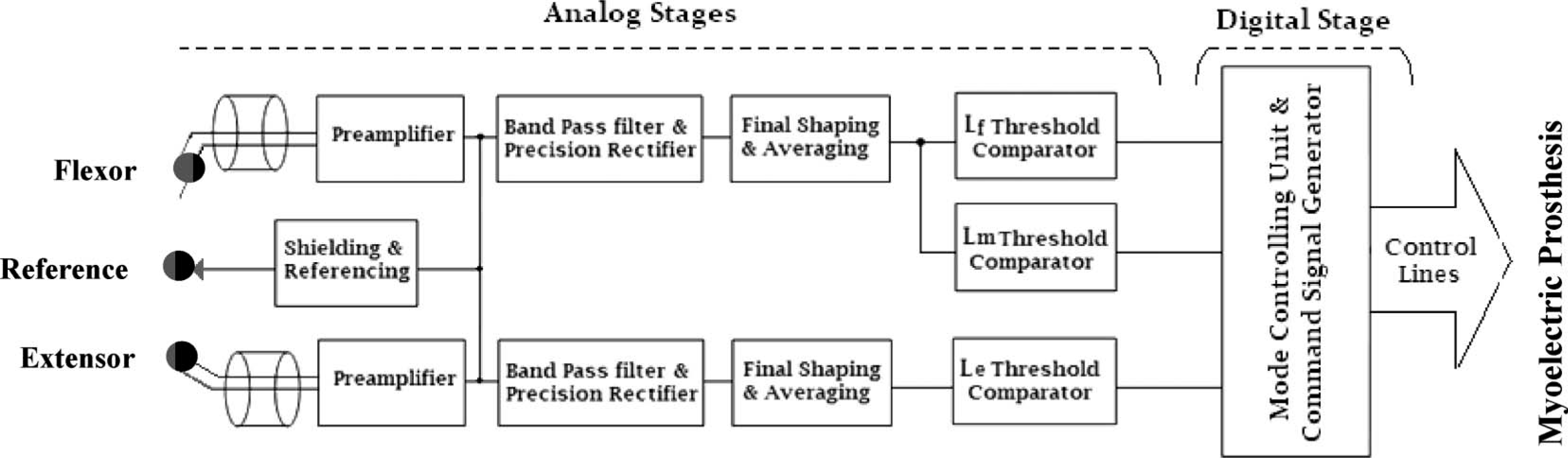
System overview with a block diagram displaying the various signal processing stages of the myoelectric control unit. The digital processing stage takes place after the comparator stage and is responsible for generating the final command signal required to control the operational mode of the prosthetic device.
While the prototype tested and described herein incorporated low-power DIP package-type components to allow in-process design modification, the final design utilizes low-power surface-mount components on a compact printed circuit board. The total hardware component cost did not exceed 200 US$ which would be further reduced for bulk production. A two-stage design was chosen to allow interested parties to modify and adapt the circuit in any way they may choose. An initial analog stage was chosen for signal acquisition, amplification and processing so that it would be easier to modify components without the need for microprocessor coding as in the case of entirely digital circuits; 24 a digital stage was only employed for mode switch monitoring and execution. This second stage may be dropped if a single-mode-of-operation myoelectric prosthesis is chosen, or if an alternative mode switching mechanism is required. The circuit was battery-operated (∼7 V Li-ion rechargeable battery 750–1000 mAh) and depending on system utilization, the battery would hold sufficient charge for 2–4 days use prior to recharging. The input stage was characterized by high impedance (about 10 GΩ) minimizing the current flow between the user and the device (less than 10 pA). Dry surface electrodes were used to measure the summation of the action potentials generated below the electrode surface. Benchmark standards on electrode placement, as well as basic EMG signal processing, were followed. 25
The differential input amplifier, seen in the pre-amplification stage in Figure 2, was used to reject stray voltage as well as common half-cell potentials. The DC offset originating from the lead input current passing through the EMG electrode was accommodated by using an input amplifier with high input impedance and a small input bias.
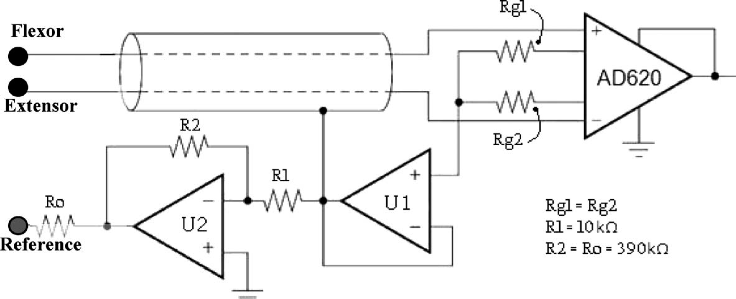
The pre-amplification stage.
The output of the various stages of signal acquisition, processing, and control were monitored using a DATAQ Instruments (Akron, OH, USA) data acquisition system. The circuit design incorporated an integrated circuit instrumentation amplifier AD620 (Norwood, USA) for the input stage. In order to maintain EMG signal stability, regardless of changes in body temperature (or in any other dynamic physical parameter), a reference feedback circuit from the body was introduced as shown in Figure 2.
As most of the EMG signal is generally contained within the range of 50–150 Hz, 26 the system utilized a cascade of first-order high pass and low pass Butterworth filters as a band-pass filter, with a −20 dB/decade roll off, and cut-off frequencies sufficient for the frequency band of interest. Voltage followers (buffers) were employed after the filters to prevent each section's input impedance from loading the previous section. This stage was followed by a precision full-wave rectifier (Figure 2), which utilizes the monolithic instrumentation amplifier AD620, a modified form of the classic three op-amp approach; 27 resistors Rg1 and Rg2 average the voltage of the differential electrode pair to sense the common voltage originating from the displacement current that flows into the body from the stray capacitance of nearby power lines. Cable capacitance and leakage are reduced through the U1 buffer voltage guard, connected to the input cable shield. 28 To protect from transient currents that may flow from U2 when the circuit is powered up, Ro was included. 29 The typical small signal (−3 dB) bandwidth frequency response at a gain of 100 was 120 kHz, the slew rate is 1.2 V/μs, and the settling time to 0.01% with a 10 V step is 15 μs. 27
In the final shaping and averaging stage, seen in Figure 3, an amplification circuit with adjustable gain was used to determine the appropriate gain for any individual amputee. Considering that the residual limb condition varies among amputees, with varying mass and function of the residual limb muscles, adjustable gain is essential for obtaining sufficient signal amplitude.
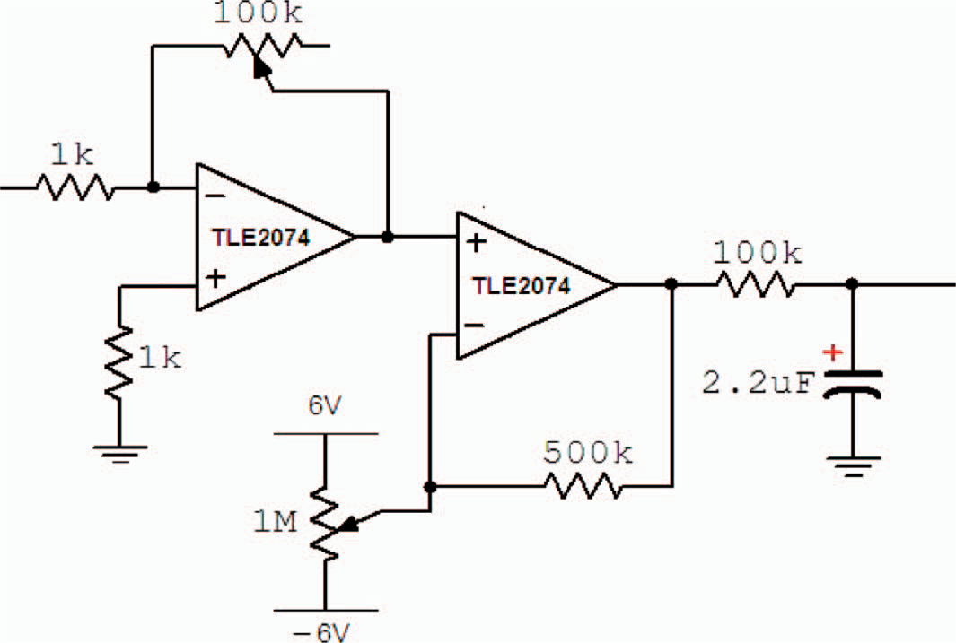
The final gain amplifier, dc-offset amplifier, and the averaging stage (Integrator).
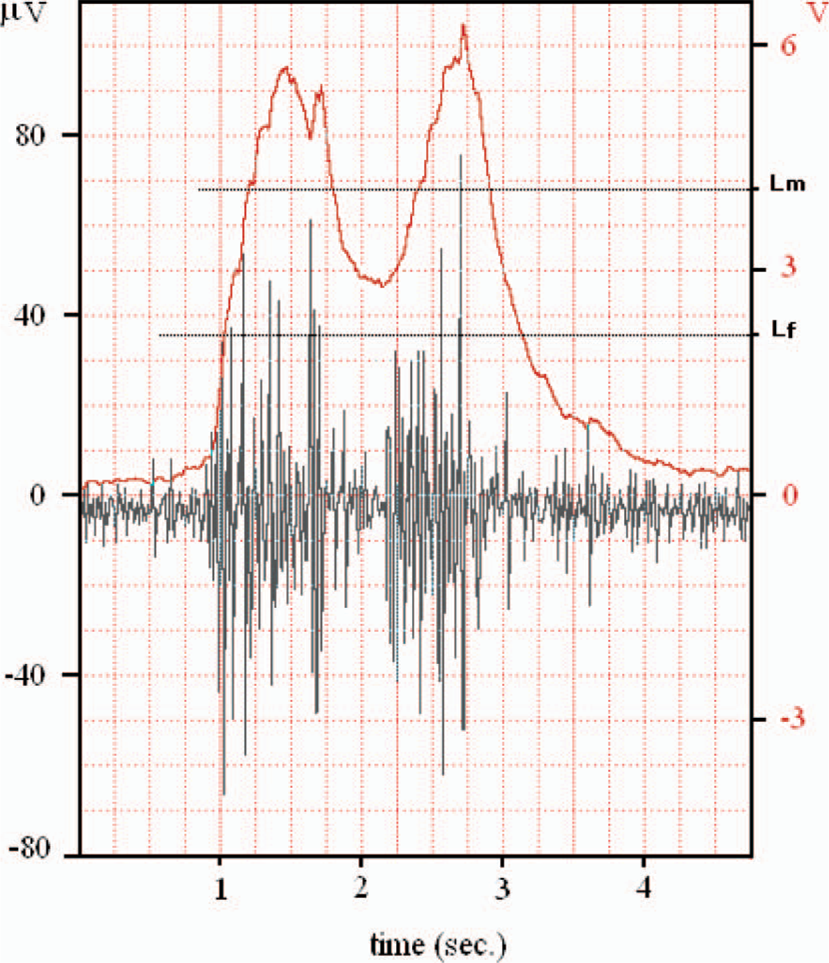
A simple offset control scheme was utilized to constantly adjust the base-line by adding a DC component to the signal. The signal was then averaged using a low pass filter with a low cut-off frequency (Figure 3). The resulting signal, usually termed the ‘processed myoelectric signal’ (PMES), represents the force of muscle contraction, and in turn, the level of muscular activity used to control the powered terminal device (Figure 4). The amputee learns to control the amplitude of this signal (force of contraction) in order to issue the specific command signal and/or threshold required for the control of the myoelectric prosthesis. At any given time the system is monitoring the PMES from each of the two channels (the extensor and flexor muscle groups).
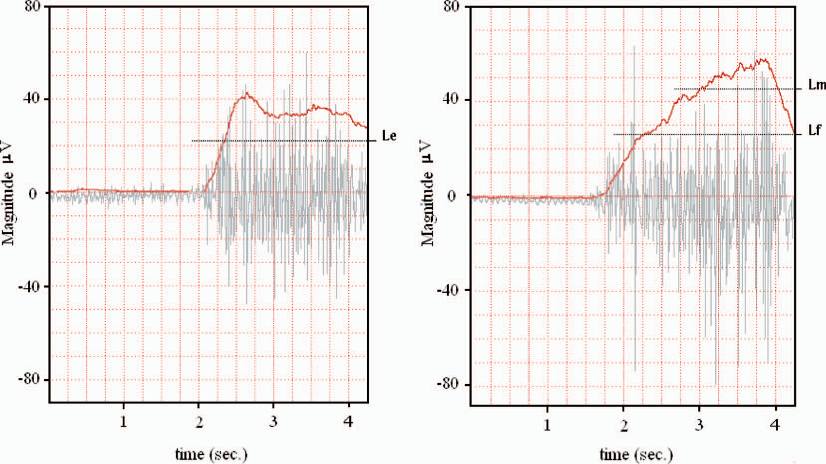
(left) A sample extensor muscle group surface EMG and the processed myoelectric signal (PMES). The threshold line (Le) required to activate the extensor (antagonist) function can also be seen. (right) A sample flexor muscle group surface EMG and the PMES which corresponds to the force generated in the active muscle group. The figure also shows the flexor thresholds Lf and Lm required to activate the flexor (agonist) function and switch the mode of operation, respectively.
The specific force of contraction (threshold) required to initiate different commands to the myoelectric prosthesis is monitored using a comparator that compares the PMES with the assigned threshold voltage. The system sets three thresholds as a comparison reference, as seen in Figure 4: The extensor muscle command threshold (Le), the flexor muscle command threshold (Lf), and the mode switching threshold (Lm), which is responsible for mode switching. Since the PMES may not be perfectly smoothed by the averaging circuit and it may contain a small noise component, a modified comparator (Schmitt trigger) was used to produce a stable level-crossing switch by introducing hysteresis in the control switch. This hysteresis in the system response, shown in Figure 5, can be adjusted both in terms of threshold by the variable voltage reference V_adj that cover the full range of the PMES (from zero up to about + Vcc), and margin of hysteresis controlled by the resistance of R1 and R2. Along with the gain stage, the range of voltage in which the Schmitt trigger can be adjusted is sufficient to cover any contraction amplitude command signal threshold for the potential user.
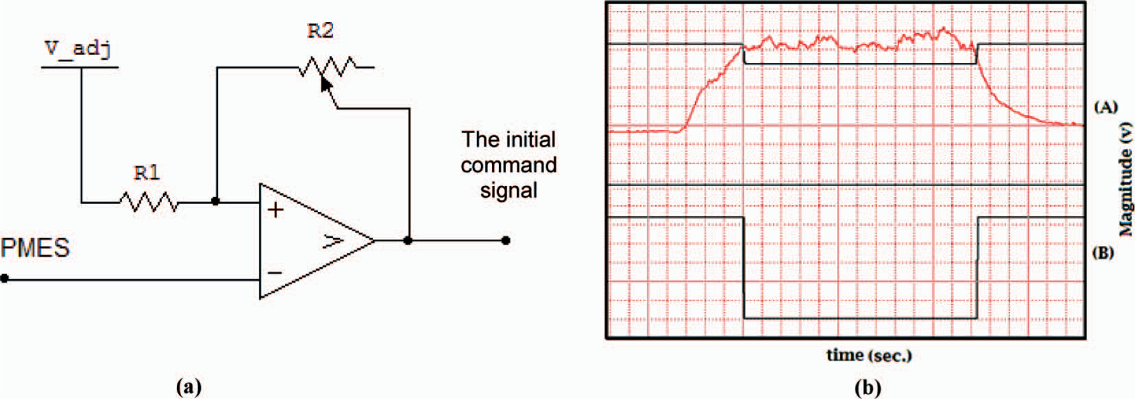
(a) The PMES input signal is encoded into an initial digital command signal. The parameters that can be adjusted are the threshold via V_adj, and the hysteresis via R2. (b) The top half (A) displays the PMES overlapped with the command threshold level, while the bottom (B) shows the Schmitt trigger output.
The digital component of the control circuit is responsible for command monitoring and mode switching. After the mode switching comparator has made the decision as to whether or not the forearm flexor muscles' contraction is strong enough to initiate mode switching, the mode switching circuit determines whether or not the mode switching sequence is correctly executed. The timer parameter in the processing program is responsible for the mode switching decision period. The decision window (timer) starts when performing a supra-threshold (Lm) contraction in the flexor muscles and ends with the relaxation of the same muscle group to a level below Lf. The variable decision window period can be reduced during the training session by minimizing the time required by the user to correctly complete the switch command. Should the user relax the flexor muscle contraction to below Lf prior to completing the second contraction in the switch command sequences, the mode is not switched and the timer is reset.
The mode switching sequence (MSS) aims to ensure that the user can intentionally and voluntarily switch the mode rapidly and with high precision in a simple manner. The system response to the command signal depends only on the user's speed and force of muscle contraction, both of which may be improved with training.
The flowchart in Figure 6 illustrates the processing scheme of the mode control unit. As the user operates the device in a specific mode, the two antagonist motions of the terminal device are controlled by the activation of the respective flexor or extensor muscle groups. The mode switching decision window initiates once the Lm threshold is first exceeded, and the mode is switched if the command sequence is executed within that window.
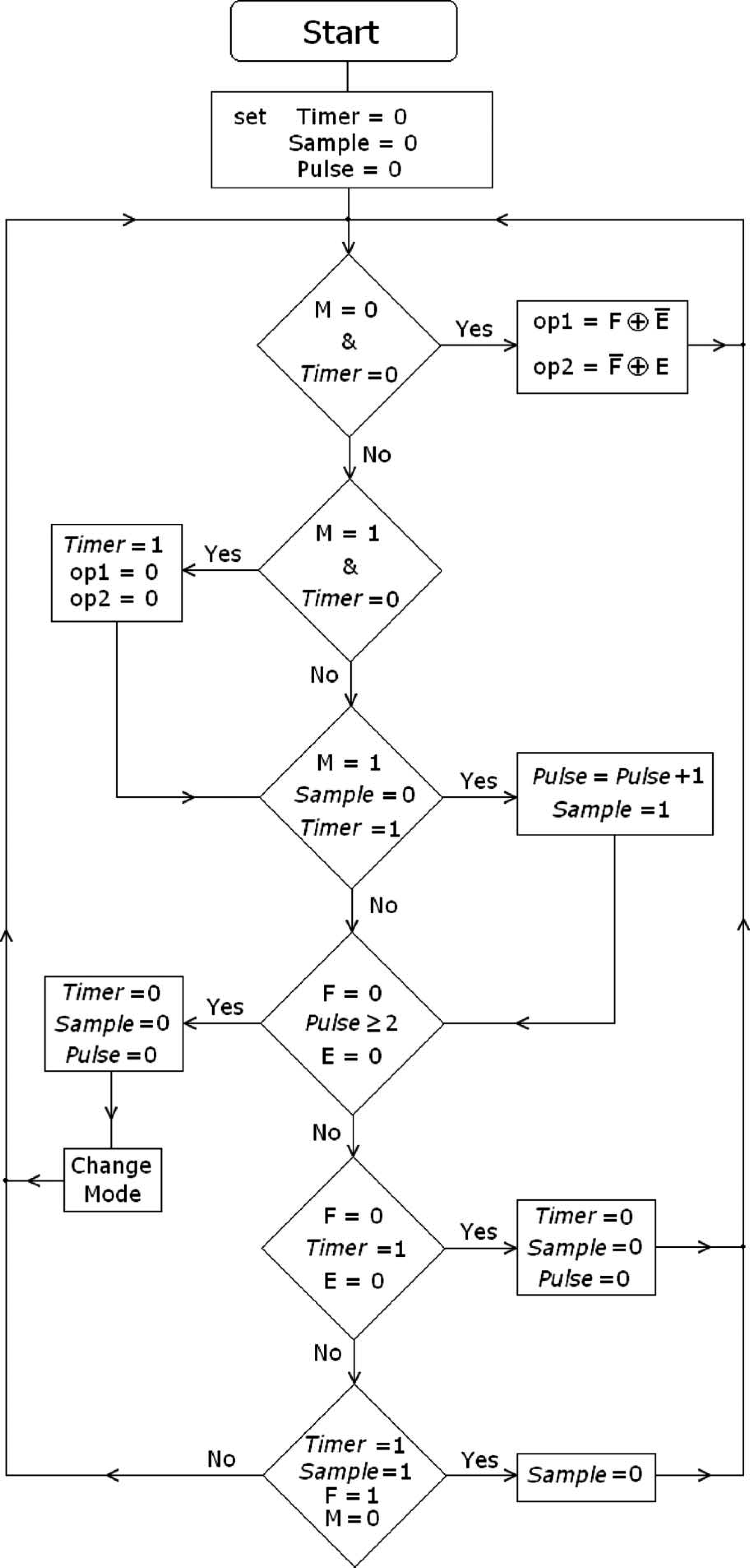
The flowchart describes the processing scheme of the mode control unit. M, E and F indicate whether or not the thresholds Lm, Le and Lf have been respectively reached by carrying a value of 1 or 0. The six ‘If’ statements cover all the possible scenarios of whether or not the MSS is completed successfully, as well as controlling each mode via F and E inputs. At each step, the last stored value of inputs M, E, and F is used. These have a value of one only if the thresholds Lm, Le and Lf, respectively, are exceeded. Otherwise, they have a value of zero. Variables op1, op2 and md represent the command signal for the terminal device such that op1 and op2 perform the two antagonist motions of the same mode, and md determines which mode to operate in. Timer represents the decision period and is dependent on how fast the MSS is completed; Sample represents the flag to count the correctly executed pulses. Finally, Pulse represents the total number of pulses correctly executed. The mode is switched if Pulse ≥ 2, by reversing the value of the md output bit.
Once Lm is exceeded, the decision period starts by setting Timer to logical one. During this decision period, the correct pulses are counted until the period is terminated. If the correct numbers of supra-threshold pulses (two or more) are applied, the mode will be switched; otherwise the mode will remain unchanged. At a 20 MHz clock frequency the controller is able to execute the six ‘if statements’ within 1.2 μs (much faster than the time scale of human motion).
Results
In order to evaluate the system performance, twelve intact subjects and four transradial amputees were recruited to participate in a series of tests. All test subjects were healthy males aged 20–40. The transradial amputees had not previously used a myoelectric prosthesis but, rather, relied on a merely aesthetic prosthesis. The amputees did not suffer from any prominent muscle atrophy. The proposed research was reviewed and approved by the Ethics Committee at the Jordan University of Science and Technology.
The test subjects were consolidated into two groups, intact versus amputees, as no significant difference in performance was exhibited within the groups. Analysis of Variance was used to compare task execution times between the intact and amputee groups, where three trials were recorded per subject for each task (n = 3). Statistical significance was set at p = 0.05. A combination of a robotic arm and visual feedback displaying the PMES overlaid with the respective command thresholds (Figure 4) on a computer monitor were used to train and subsequently test the subjects on generating the required signals to accurately control the myoelectric prosthesis. The visual output of a filtered and amplified single-contraction control EMG signal, recorded from the surface electrodes on either side of the residual limb's forearm muscles (the prime flexors and extensors), can be seen in Figure 4. The PMES appears as a solid line, representing the result of signal rectification, gain, offset, and, finally, averaging; thus encoding the force of contraction.
When operating the system in the grasp mode, a flexor muscle contraction (PMES) above Lf (baseline threshold) closed the prosthetic hand (grasp), while extensor muscle contraction above Le opened it (release). Alternatively, when the prosthesis was operated in wrist rotation mode, flexor muscle contraction above Lf caused pronation of the prosthetic hand, while extensor muscle contraction above Le caused supination of the prosthesis. The PMES (solid line in Figure 4) of the extensor and flexor muscle groups can be seen overlaid with the surface EMG from their respective electrodes. A flexor PMES above Lm, triggers the processor to monitor for the switch command sequence. If issued correctly, the mode of operation is switched. The switch command sequence employed herein is based on producing at least two consecutive flexor pulses that exceed Lm, while maintaining the contraction above Lf between the two pulses, otherwise the microprocessor is reset. A correct execution of the switch command sequence can be seen in Figure 7, in which the mode is successfully switched.
Sample mode switching command signal. The capacitive component in the averaging stage delays the falling edge for the PMES, allowing greater control in issuing the proper switch command by producing contractions between the Lf and Lm reference thresholds.
A feedback signal is relayed to the user once the prosthesis receives a supra-threshold mode-switching signal, by utilizing a Jameco Electronics coin-type tactile stimulation vibrator (Belmont, CA, USA). This feedback mechanism proved particularly critical during the training phase of operation; whereby the user is informed as to the operational status (mode) of the control system.
After an initial training and fine-tuning session for all test subjects, employing the visual feedback system aimed at optimizing the rapid execution of the required command sequence, the subjects attempted the performance evaluation test. The intact limb of the test subjects was immobilized to a support frame to prevent movement of the wrist, palm, and fingers. The amputees, on the other hand, were merely asked to rest the residual limb on the table during the test. The subjects were now prompted to implement a series of predetermined tasks of increasing complexity. The time (in seconds) required for the correct execution of various tasks by the robotic arm was calculated. These tasks included basic operational tasks, such as: Grasp (G), Release (R), Switch Mode (SM), Pronate (P), and Supinate (S); in addition to more complex tasks that mimic basic functionalities, such as: clockwise rotation for a door knob or key (G-SM-S), manipulating an object (G-Hold[2sec]-R), and counterclockwise rotation (S-SM-G-SM-P), which are labeled C1 through C3, respectively, in Figure 8.
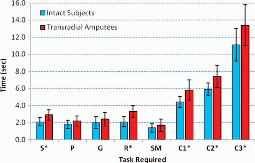
Bar graph representing the mean time required to execute a number of simple tasks: Grasp (G), Release (R), Switch Mode (SM), Pronate (P), and Supinate (S), followed by a series of more complex tasks: G-SM-S (C1), G-Hold[2sec]-R (C2), and S-SM-G-SM-P (C3). Error bars measure the standard deviation, and asterisks (∗) indicate tasks in which a significant difference in performance between the intact and amputee test groups was observed (p < 0.05). Four amputees and 12 intact subjects were tested (n = 3).
During the evaluation process visual feedback was not available to the test subjects, while tactile feedback from the mechanical vibrator was permitted.
Discussion
The command signal generated from the prime flexors and extensors was able to effectively control the motion of the terminal device (robotic arm) in both the grasp/release and the pronation/supination modes of operation by both the amputees and the intact subjects. The agonist and antagonist motions in each mode were successfully controlled by the test subjects voluntarily producing a contraction with PMES above the baseline threshold required for activation of the respective prosthetic functionality.
A slight, yet significant (p < 0.05), difference in performance was found between the intact test subjects and the transradial amputees in tasks requiring the activation of the extensor muscle group (S, R, C1, C2, and C3). On the other hand, differences in task execution time were not significant (i.e., p > 0.05) between the two groups when considering simple tasks requiring the activation of the flexor muscle group (P, G, and SM). The mean task execution times (time required to successfully execute the task) are shown in Figure 8, an asterisk (∗) indicates a statistically significant difference in performance between the two groups. This is most likely due to the larger mass of the flexor muscle group in comparison to the extensor, as well as the disproportionate loss in extensor function in the transradial amputees. Although from a functional perspective, both groups performed equally as well, as noted from the high correlation in performance between the two groups among respective tasks. The time required to perform the various tasks includes both the command time as well as the response time of the robotic arm. As the number of test subjects increased so did the variance in measurements. Although the variance within repeat trials for the same subject was low, variation in performance among the test subjects increased the overall variance per task. Nonetheless, the bar chart reveals the system's narrow standard deviation and, as such, accurate repeatability of the required tasks by the test subjects. As expected, more complicated tasks required a longer execution time, and the effect of the training period in reducing the time to execute the required task was most evident during training on these more complicated tasks. All subjects had been allowed to train until they felt sufficiently comfortable with the level of command they had over the prosthetic arm.
Conclusions
Although myoelectric prosthesis manufacturing and design has drastically advanced since the earlier body contortion prostheses, they have, unfortunately, become cost prohibitive for most amputees. The myoelectric control design presented in this work illustrates a functional and feasible customizable design. The hope is that such affordable and simple design solutions to common health challenges may pave the way for a greater number of people to benefit from the technology and eventually stimulate more work on functional low-cost designs of myoelectric prostheses.
Footnotes
Acknowledgements