
Abstract
The motion of the current prostheses is sequential and does not allow natural movements. In this work, complex natural motion patterns from a healthy upper limb were characterized in order to be emulated for a trans-humeral prosthesis with three degrees of freedom at the elbow. Firstly, it was necessary to define the prosthesis workspace, which means to establish a relationship using an artificial neural network (ANN), between the arm-forearm (3-D) angles allowed by the prosthesis, and its actuators length. The 3-D angles were measured between the forearm and each axis of the reference system attached at the elbow. Secondly, five activities of daily living (ADLs) were analyzed by means of the elbow flexion (EF), the forearm prono-supination (FPS) and the 3-D angles, from healthy subjects, by using a video-based motion analysis system. The 3-D angles were fed to the prosthesis model (ANN) in order to analyze which ADLs could be emulated by the prosthesis. As a result, a prosthesis kinematics approximation was obtained. In conclusion, in spite of the innovative mechanical configuration of the actuators, it was possible to carry out only three of the five ADLs considered. Future work will include improvement of the mechanical configuration of the prosthesis to have greater range of motion.
Introduction
Sequential movement is a common aspect in current prostheses. However, sequential action does not allow natural movements which are strongly desired by users. Some examples of these devices are the NY Electric Elbow, the Boston Elbow and the Otto Bock Dynamic Arm. All of them incorporate a turntable to generate passive humeral rotations. 1 The Utah Arm allows simultaneous control of the elbow and hand actuators. 2 However, its pronation and supination movements were implemented at the wrist level while on a healthy upper limb they are developed at the elbow level. A prototype of an active prosthesis 3 with parallel electromechanical action for trans-humeral amputee has been developed in our laboratory (Figure 1). The actuator array for this system was developed in order to reproduce movements similar to those of a healthy upper limb. 4 The active functions of this prosthesis are prehension, prono-supination, elbow flexion-extension and humeral rotation. Pronation and supination movements are performed at the elbow level.
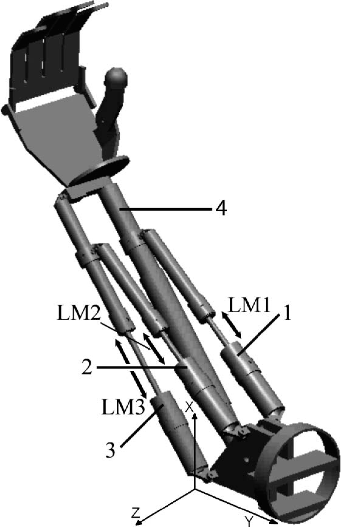
Active prosthesis with four parallel actuators. This configuration allows three active degrees of freedom at the elbow and active prehension. Each actuator has the following function: (1) Flexion-extension, pronation; (2) flexion-extension, supination and humeral rotation; (3) humeral rotation; (4) active prehension. LM1, LM2 and LM3 are the actuator lengths. Coordinate system is attached at the elbow joint. Y axis is aligned with upper arm; Z axis is parallel to elbow joint axis; and X axis is orthogonal at the Y and Z axes.
Movement analysis of the upper extremity has been studied for different purposes. Tee et al. 5 suggested a simple computational model of joint torque and impedance in human arm movements with the aim to simulate 3-D movements and to design the control of robots and human machine interfaces. Iftime et al. 6 described an automatic method based on radial basis function artificial neuronal networks to characterize the synergies between the proximal and distal arm joint angles that are typical for healthy persons when performing activities of daily living (ADL). The aim was to synthesize the control for a neural prosthesis for persons with hemiplegia. A kinematic model of the upper extremity has been described in terms of joint angles; 7,8 and it was applied in the detection of pathological movement patterns. 8 On the other hand, the upper extremity movement analysis has been focused on rehabilitation; Ramanathan et al. 9 and Romilly et al. 10 performed an analysis of the movement trajectories of an upper extremity with healthy subjects performing different activities. The objective of these studies was to develop an upper limb orthosis which helps subjects with neuromuscular disorders to be independent and reintegrated to regular life. Magermans et al. 11 determined the joint angles for some ADLs evaluating the movement range of the upper extremity. Those results showed that the joint movements of shoulder and elbow, the internal and external humeral rotation as well as prono-supination of forearm are fundamental in ADLs. 10,11 Morrey et al. 12 performed a biomechanical study with healthy subjects to determine the amount of elbow motion required for 15 different ADLs. The elbow flexion and forearm rotation were measured simultaneously by means of an electrogoniometer. Using this method a functional range of motion, elbow flexion-extension and forearm prono-supination, was obtained.
According with the studies mentioned above and considering that an active prosthesis with natural movements would represent a relevant functional improvement, we propose in this research, an active prosthesis which mimics the movements of a healthy upper limb and approximates natural movement.
Methodology
In this section we describe the methodology; first we determined the prosthesis workspace, which refers to all the points that the prosthesis can reach in 3-D space, This workspace depends on the parallel actuators array, i.e., for each set of 3-D angles between the upper arm and forearm, there is a corresponding actuator length. This relationship was modelled with an artificial neural network (ANN). After that, the movement trajectories of five ADLs were obtained from healthy subjects with a motion analysis system as follows: A set of markers were placed on the upper arm, the forearm and the joints; and the position of these markers was computed by the system and processed with methods described by Veldpaus et al. 13 and Schmidt et al. 14 As a result, natural motion patterns, characterized by elbow flexion (EF), forearm prono-supiation (FPS) and 3-D angles, were obtained. The ANN, together with the natural motion patterns, coordinated the actuators in order to produce the desired natural movements. The use of an ANN to command the electromechanical structure turned out to be appropriate to solve the inverse kinematics. 15–18 The ADLs analyzed in this article were the following: Opening a door, drinking water, pouring water from a pitcher, answering the phone, and shaking hands. Some of these activities have been analyzed by other authors. 9,10,12,14
Prosthesis workspace
The electromechanical parallel system of this prosthesis consists of four linear actuators as shown in Figure 1. This kind of actuator allows emulation of natural muscular function. 4 All ranges of motion (RoM) of the prosthesis in the workspace depend on the actuator lengths, i.e., the prosthesis workspace will be limited by the range of actuators displacement. Therefore, a relationship between the 3-D angles and the actuators length was established in order to characterize the prosthesis workspace. First, the prosthesis was placed on a support and a coordinate system was built using small sticks. Then, the coordinate system was attached to the prosthesis upper arm as shown in Figure 2. The origin was fixed at the elbow joint; the Y axis was parallel to the arm, the Z axis was aligned with the elbow joint axis, and the X axis followed from the condition of orthogonal axes. In addition, the prosthesis was set to an initial or resting position, i.e., it was extended with an approximate pronation of 90°. Moreover, it was set to different positions and the angles between the forearm and the axes were measured as follows: θx with respect to X axis, θy with respect to Y axis, and θz with respect to Z axis (3-D angles); these angles were used to model the prosthesis workspace. Also, elbow flexion and the forearm prono-supination angles were measured manually using a protractor. At the same time, the length of each actuator at each position was measured with a vernier caliper: actuator length 1 (LM1), actuator length 2 (LM2) and actuator length 3 (LM3) (Figure 1). In this way, a correspondence between the measured angles and the length of the enabled actuators during the movement was established.
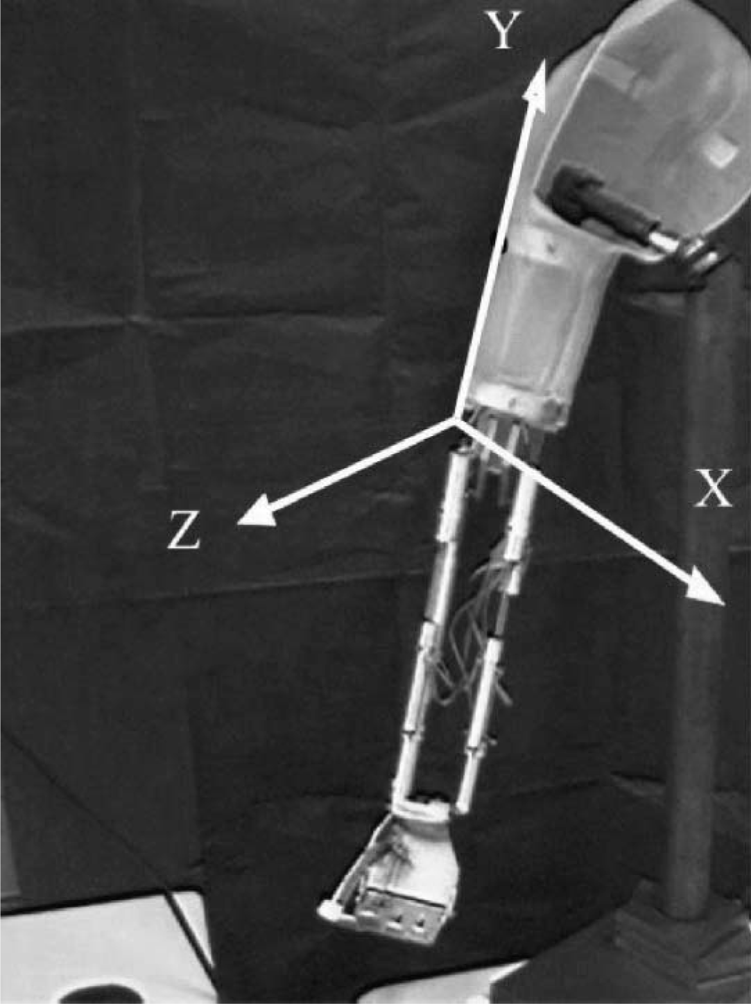
Coordinate system built with small sticks attached to the active prosthesis. The origin was fixed at the elbow joint; the Y axis was parallel to the arm, the Z axis was aligned with the elbow joint axis, and the X axis followed from the condition of orthogonal axes.
The prosthesis workspace defined with these measurements was modeled with an ANN. The angles and actuators length (ANN) were used as inputs and outputs of the model, respectively. A set of 330 input-output pairs was generated.
Motion patterns using artificial neural network
ANNs are considered universal approximators of functions; 19–21 therefore, they were used as a tool for this application, and the architecture chosen for modeling the prosthesis workspace was a multilayer perceptron (MLP) with one hidden layer, as shown in Figure 3. The purpose of using an ANN was to model the prosthesis workspace instead of specifying an explicit kinematics model. Hasan et al. used a network to model the inverse kinematics of robotic systems 15 and their results showed an excellent mapping over the workspace of the robot. As a training method, the iterative algorithm of Levenberg-Marquardt was selected. 22,23 This training algorithm was chosen because of its convergence velocity (quadratic) to the minimum error considered.
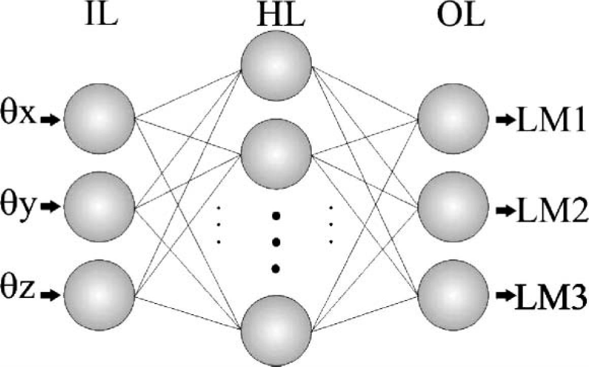
Architecture of the ANN used. Input layer (IL); Hidden layer (HL) and Output layer (OL). 3-D angles (θx, θy and θz) were input to the ANN; the output was actuator lengths (LM1, LM2 and LM3).
The ANN was trained and validated with the data set that characterizes the prosthesis workspace. All input-output pairs in the data set were random points in the prosthesis workspace. A subset of 275 pairs was chosen from a set of 330 input-output pairs in order to train the ANN; the 55 remaining pairs were used to validate the training. The k-fold technique was used to ensure that the ANN was not over-fitted. The data set was randomly divided in k = 10 partitions resulting in 33 data subsets. After, the network was trained 33 times. In each trial, 32 subsets were used as data training and one subset as test data. Then the mean squared error (MSE) was obtained. During the training, the number of neurons and the activation function in the hidden layer, as well as the goal error, were tested with different values in order to find a minimal network configuration suitable for implementation in a dedicated system. The iteration number was fixed in 1000, which means that the training algorithm finished when the desired error or the iteration number was reached. The system required three neurons in both, the input and the output layer: The 3-D angles (θx, θy and θz), and the lengths of the actuators (LM1, LM2, and LM3) respectively (Figure 3). The ANN training was accomplished via the Neural Network Toolbox of Matlab. 23
Typical patterns of the movement trajectories
Subjects
Five healthy subjects (two male and three female), right-dominant and with normal neuromuscular function, participated in this study. Their ages were between 24 and 32 years old and their heights were between 159 and 175 cm. The experimental procedure was approved by the Institutional Bioethics Committee. All subjects gave written informed consent to participate after receiving a full explanation of the experimental procedure.
Experimental set-up and data processing
In order to obtain the 3-D, the EF and the FPS angles, a rigid-body model of the upper limb was considered. It consisted of three segments: The upper arm, the forearm and the hand, which were connected by two ball-and-socket joints: the elbow and the wrist. In this model, a minimum of three non-collinear markers per segment were required to measure all six degrees of freedom (dof) of every segment. 13,14 A total of 11 reflective markers (with a diameter of 15 ± 0.5 mm) were used as shown in Figure 4. Three segment markers were fixed at the upper arm; three were fixed at the forearm close to the wrist, to record most of the prono-supination; and five joint markers were fixed at the acromion (macr), lateral (mlat) and medial (mmed) epicondyle, and lateral (muln) and medial (mrad) to the wrist flexion axis, to define the joint centers and joint axes. The position XYZ, with respect to the laboratory reference, of each marker was computed with Ariel Perfomance Analysis System (APAS) (Ariel Dynamics Inc., USA) during the movement; the trajectory of the upper limb was known with this information. In this work, APAS, a video-based 3-D motion analysis system, was used with four cameras with a rate of 30 frames per sec (enough for a normal motion 24 ). The experimental set-up is shown in Figure 5.
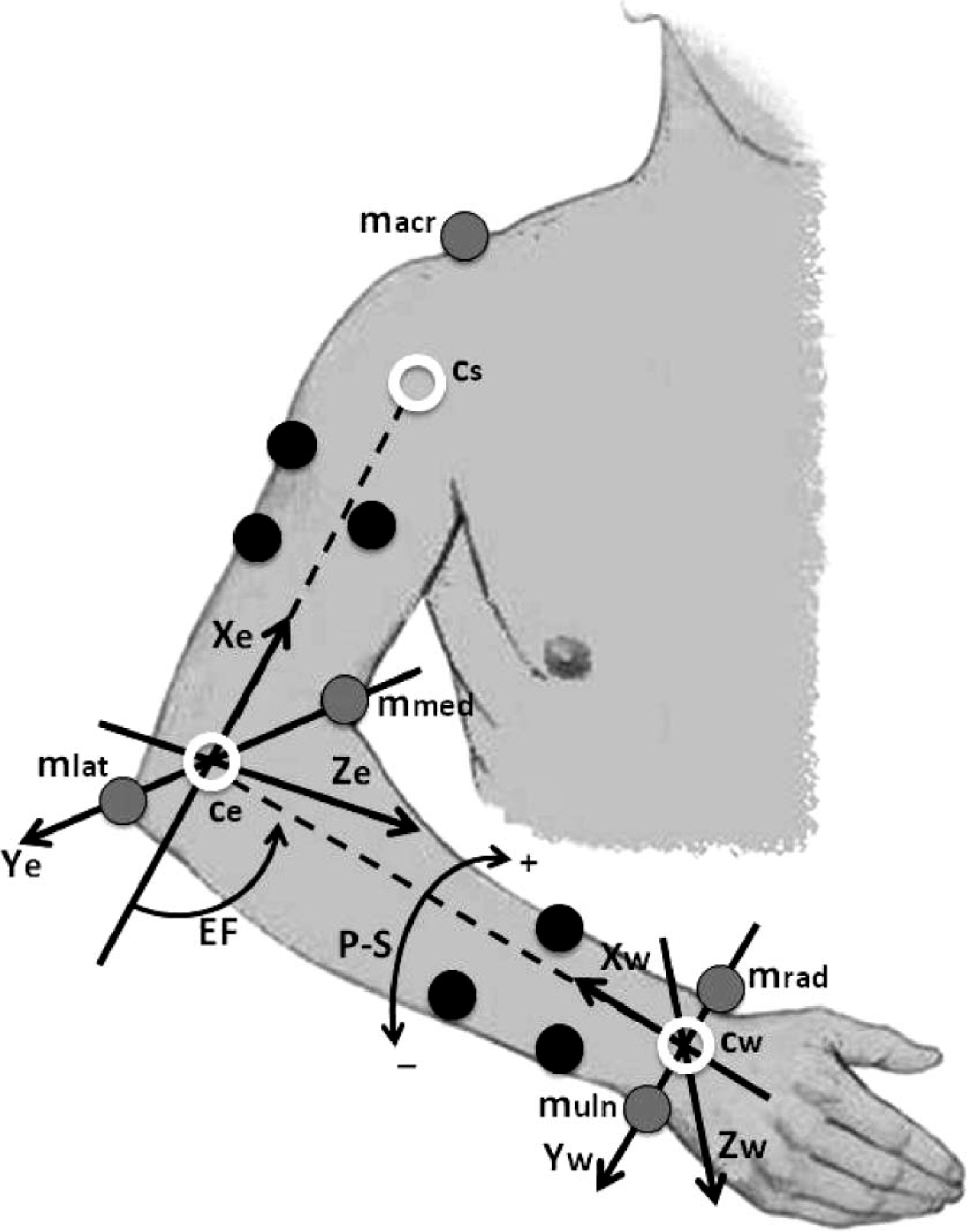
Markers location on the right upper limb. Gray markers define the joint axes, shoulder, elbow and wrist. Black markers define the segments upper arm and forearm. White circles represent the joint centers determined with the gray markers. Dashed lines are the segment axis. Joint coordinate systems on the elbow and the wrist were defined to compute the 3-D, EF and FPS angles.
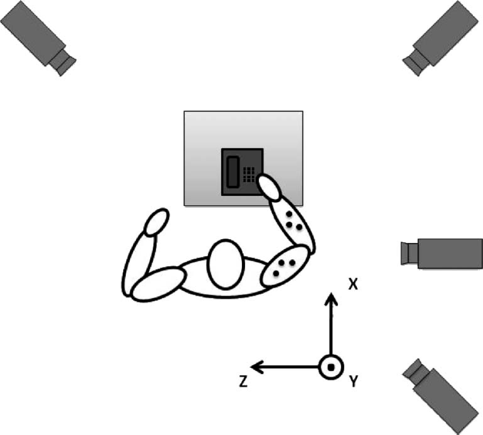
Top view of the set-up for tracking tasks.
In order to obtain natural movement patterns of ADLs, the subjects carried out each of these activities in the usual way. The video acquisition duration depended on the time required to develop each task; subjects were only restricted to start at rest position and come back to the same position at the end of the task. The rest position was considered when the upper limb was extended next to the body. The five ADLs chosen were:
Opening the door. The subject moved his/her limb towards the handle of the door, which was placed at a height of 1 m from the floor, and turned it open, then the upper limb pushed or pulled the door. Finally, (s)he released the handle.
Drinking water. The subject moved his/her limb towards a glass placed on a table at height of 0.76 m from the floor. Then (s)he grabbed the glass, took it to the mouth, and returned it to the table.
Pouring water from a pitcher. The subject moved the limb towards a water container on a table at height of 0.76 m from the floor; (s)he poured the liquid into the glass and returned the container to the table.
Answering the phone. The subject moved his/her limb towards the phone placed on a table at height of 0.76 m from the floor. Then (s)he grabbed the phone, took it to the ear, and returned it to the table.
Shaking hands. The subject placed his/her hand in front of him/her at a height of 1 m from the floor, approximately, and then (s)he moved the forearm up and down three times.
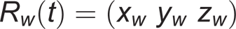
A static reference measurement was used to compute the locations of the joint markers and joint centers with respect to the segment markers and to define the neutral joint orientation. After this measurement, the joint markers were removed in order to avoid disturbances in the positions of the markers due to large skin movements at the joints. As defined by Schmidt et al., 14 the center of the wrist axis, at time t, was the middle between ulnar and radial wrist marker (Figure 4):
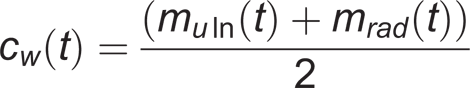
where m uln(t) and m rad (t) are the position vectors of the ulnar and radial wrist markers.
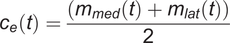
The center of the elbow joint is the middle between the medial and lateral elbow markers:
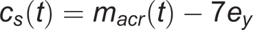
The shoulder center was located at 7 cm inferior to the acromion marker:
14
The joint centers, at any time, were calculated from the joint marker positions in the static reference measurement. The joint marker positions were obtained by means of the algorithm presented by Veldpaus et al.
13
After that, the orientations of the wrist and elbow coordinate systems, with respect to laboratory reference, were computed, and a rotation matrix for each system was obtained:

respectively, where x w , y w , z w and x e , y e , z e are the axes of the wrist and elbow coordinate systems. The relative orientation between wrist and elbow joint coordinate systems yielded the 3-D, EF and FPS angles, using rotation matrices. All these, were processed in Matlab® 7.1.0.246 (R14).
Motion patterns and ANN
The 3-D angles, measured between the forearm and the elbow coordinate system axes for each ADL, constitute the information necessary to perform the prosthesis motion patterns. The 3-D angles, obtained from each ADL, were submitted to the ANN previously trained with the 3-D angles measured from the prosthesis. The response of the network corresponded to the length that each prosthesis actuator had to reach in order to reproduce the desired ADL.
Results
The motion patterns of each task were characterized with the 3-D, EF and FPS angles from healthy subjects. With the prosthesis mounted on a fixed support the workspace (3-D angles) was described. Some tasks required movement outside the prosthesis workspace.
Motion patterns
The natural trajectories of the ADLs were characterized by means of 3-D, EF and FPS angles. Figure 6 shows a typical RoM of EF and FPS angles of the healthy upper limb for all the tasks considered. The mean value of the minimum and maximum angle required to carry out each task is showed in Table I. For each mean value, a standard deviation (SD) is presented. Negative and positive values in the FPS angles indicate supination and pronation movements, respectively. The positive value in the minimum column of FPS for the task labeled ‘pouring water from a pitcher’ shows that only the pronation movement was necessary.
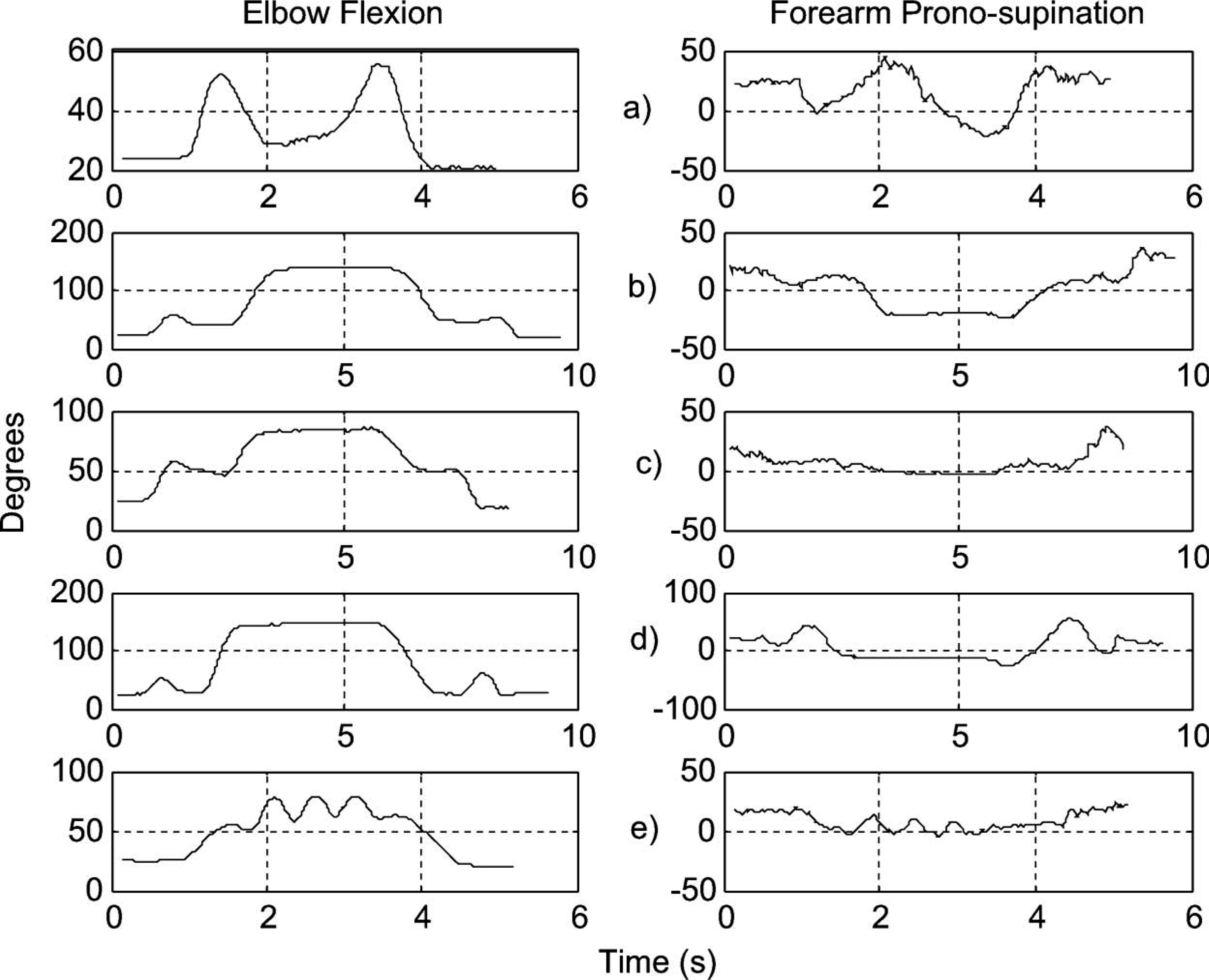
Typical range of motion (elbow flexion and forearm prono-supination angles) of the upper limb during ADLs: (a) Opening a door; (b) Drinking water; (c) Pouring water from a pitcher; (d) Answering the phone; and (e) Shaking hands.
Amount of upper limb motion required to carry out selected tasks. Mean ± SD.
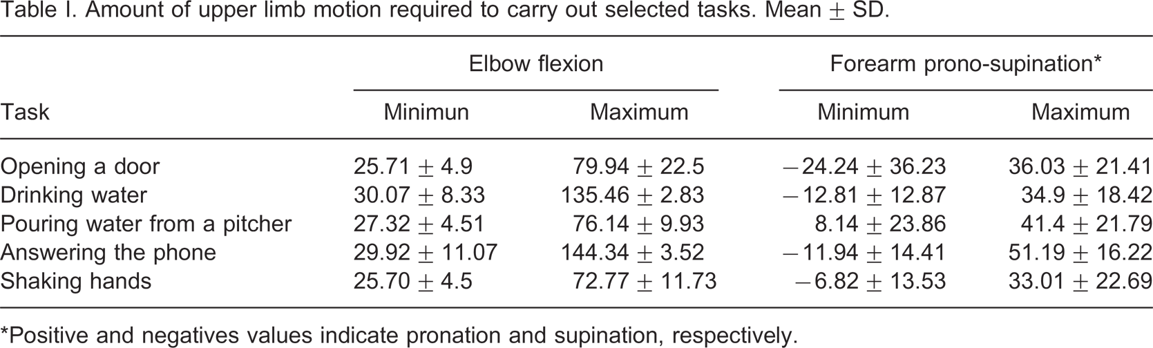
∗Positive and negatives values indicate pronation and supination, respectively.
Table I shows that the ADLs ‘drinking water’ and ‘answering the phone’ needed an EF angle greater than 130°, while the maximum flexion angle of the prosthesis was 81°. This means that these tasks can not be performed for the prosthesis in its current state. However, if the actuators’ working lengths are increased, this problem will be solved. The trajectories of these tasks were superimposed on the prosthesis workspace in Figure 7. As expected, parts of the trajectories did not match those of the prosthesis. This is consistent with our data of the RoM of a healthy upper limb and the RoM of the prosthesis.
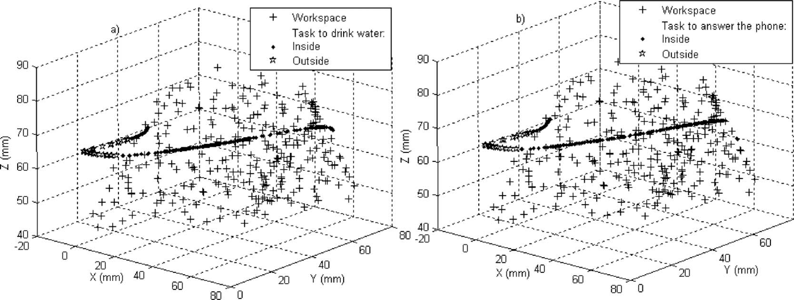
Trajectories that did not match with the prosthesis workspace. Some points (stars) of each task were not inside the prosthesis workspace. (a) Drinking water; (b) Answering the phone. All the points (+) characterize the prosthesis workspace.
Prosthesis motion
ANN
During the training, several configurations of ANNs were tested, each with a different number of neurons and activation functions in the hidden layer, as well as different error limits. The purpose was to find a minimal configuration of neurons suitable to be implemented in a dedicated system. As a result, the architecture of the ANN was three neurons in the input layer, seven neurons in the hidden layer and three neurons in the output layer. The activation function in the hidden and output layers was f(x) = 2/(1 + e −2x ) and f(x) = x, respectively. The goal error reached with this configuration was 0.01. The training algorithm had two stop options, the goal or the iteration number; the goal was always reached before 1000 iterations for all the trials.
The results from the validation data (Figure 8) compare expected and predicted lengths for the three actuators. The slope (m) and intercept (b) that define the comparison line y = mx + b that best fits the data are shown for each output. The ideal case implies lines with m=1 and b = 0. Table II shows the linear regression parameters for training and validation data.
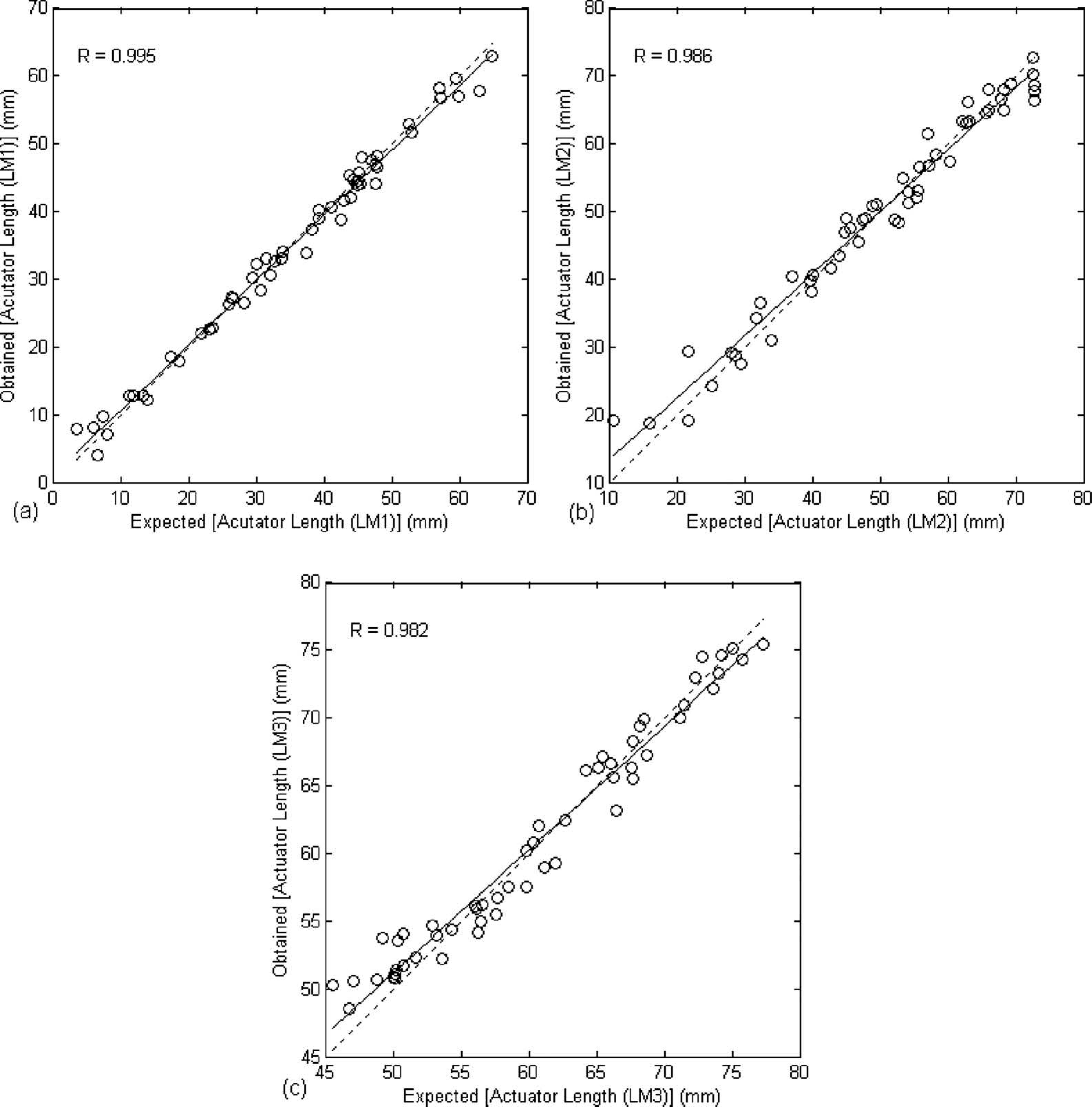
Comparison between the expected results and those obtained with the trained ANN. The dashed line corresponds to the identity (y = x) and the solid line to the regression of the comparison data. R is the correlation coefficient. (a) validation data of the LM1, average error 1.75 mm; (b) validation data of the LM2, average error 2.83 mm; and (c) validation data of the LM3, average error 1.79 mm.
Parameters of the linear regression, y = mx + b, for the training and validation data.
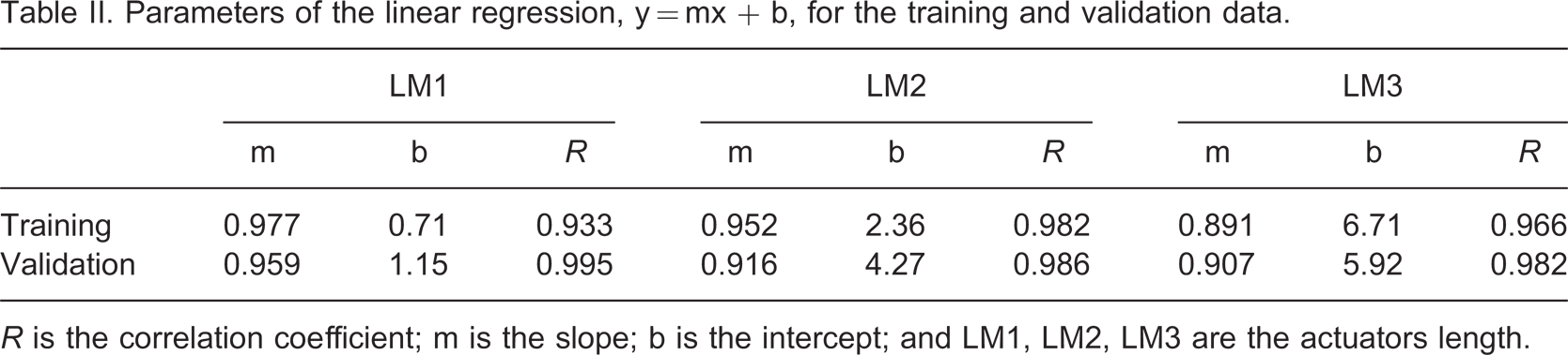
R is the correlation coefficient; m is the slope; b is the intercept; and LM1, LM2, LM3 are the actuators length.
The network built an associated function between the 3-D angles and the lengths that the actuators had to reach. The correlation coefficient (R) between the expected and predicted values was greater than 0.9, this means, an average error of 2.12 mm.
In order to ensure that the ANN was not over-fitting, the k-fold technique was used. The MSE obtained for each ANN output was 4.17 ± 5.41 mm, 10.2 ± 7.6 mm and 5.82 ± 5.54 mm for LM1, LM2 and LM3, respectively. The error obtained with the final ANN used was 1.75, 2.83 and 1.79 mm for LM1, LM2 and LM3, respectively.
Trajectories and ANN
When the prosthesis performed a specific task, the actuators had to adjust to different lengths to reach all the points required for the task. The actuator length adjustment (LM1, LM2 and LM3) was a function of the angles which characterized the natural movements of a healthy upper limb. Then, the 3-D angles obtained from each ADL were applied to the prosthesis model (ANN) and its response was the length that each actuator had to reach to reproduce the desired natural movement.
Figure 9 represents the process described above for the task ‘opening a door’. The actuator lengths required to accomplish the trajectory of the healthy upper limb are shown. Considerable variations were observed in LM1 and LM2, because both actuators have direct participation in the flexion and extension movements of the prosthesis. The first variation, until n = 50, of the lengths correspond to the trajectory segment where the upper limb reached the doorknob; the second, from n = 50 to n = 125, correspond to the movement of turning the doorknob, and the last variation, from n = 125 to the end, correspond to the action when the upper limb released the doorknob and went back to the resting position.
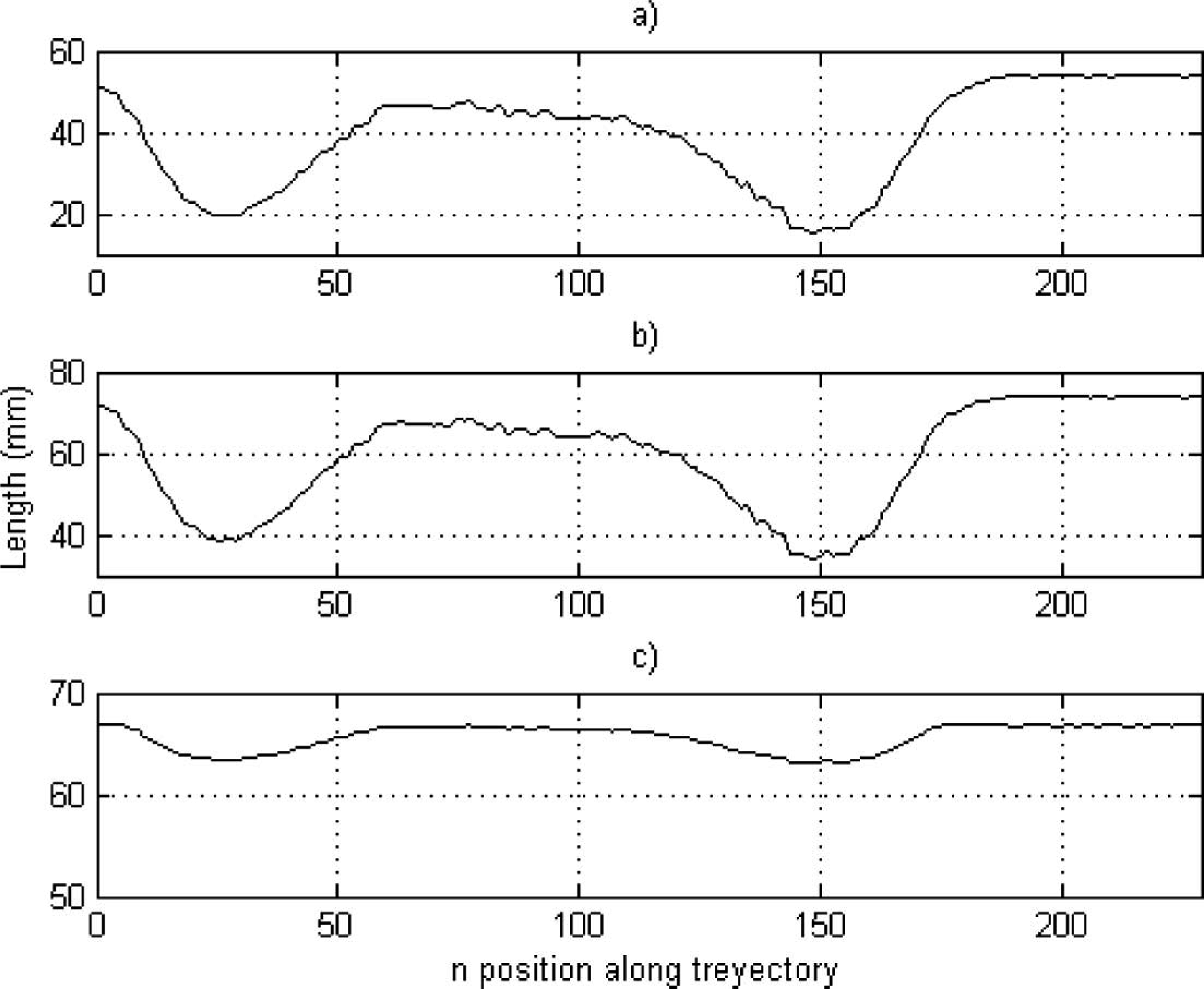
Lengths reached by the actuator (a) 1 (LM1); (b) 2 (LM2); and (c) 3 (LM3) during the opening a door task. Correspondence between the flexion and extension movement and contraction and distention of the actuator, respectively, can be observed.
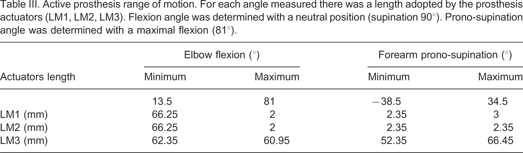
With the model of prosthesis workspace and the angles obtained from ADLs, it was possible to determine which movements from those considered, the prosthesis was capable to mimic. The 3-D angles of the ADLs were fed to the prosthesis model, and its response for each ADL was superposed in the prosthesis workspace (Figure 10). If the ADL trajectory matched with prosthesis workspace, it meant that the prosthesis could mimic the ADL successfully. This is in agreement with the RoM necessary to carry out the ADL (Table I) which matched with the RoM of the prosthesis (Table III).
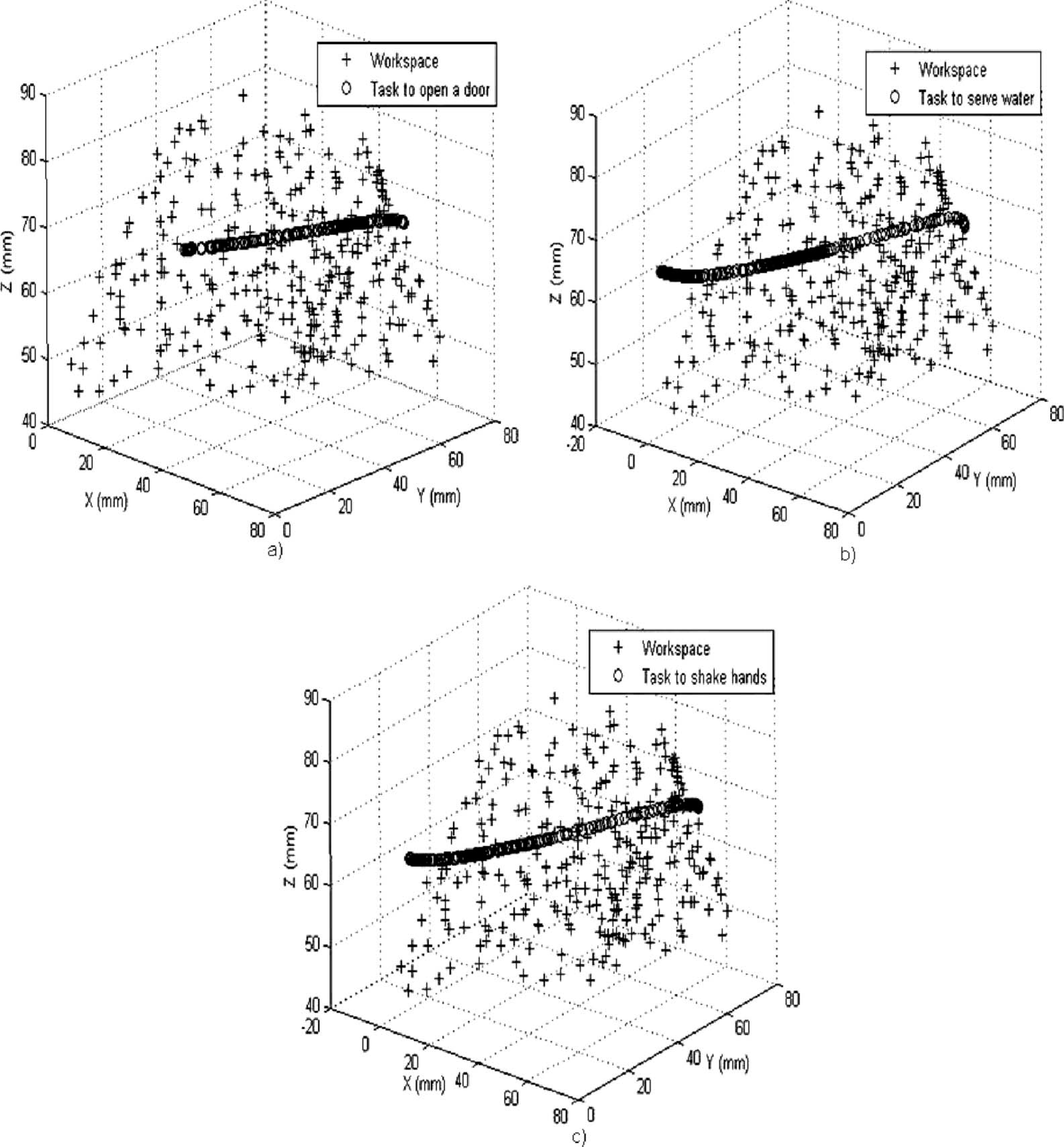
Tasks superposed on the prosthesis workspace: (a) Opening a door; (b) Pouring water from pitcher; and (c) Shaking hands. The trajectory of these tasks matched with the prosthesis workspace.
Active prosthesis range of motion. For each angle measured there was a length adopted by the prosthesis actuators (LM1, LM2, LM3). Flexion angle was determined with a neutral position (supination 90°). Prono-supination angle was determined with a maximal flexion (81°).
Discussion
Motion analysis results of the healthy upper limb were similar to those from other authors. For instance, in the case of ‘opening a door’, Morrey et al. 12 reported a minimum and maximum EF angle of 24° and 57.4°, respectively, and a minimum and maximum FPS angle of 23.4° and 58.8°, respectively; Romilly et al. 10 reported a minimum and maximum EF angle of 42° and 76°, respectively; and a minimum and maximum FPS angle of 7° and 52°, respectively. In this work, a minimum and maximum EF angle of 25.71° and 79.94°, respectively; and a minimum and maximum FPS angle of 24.24° and 36.03°, respectively, were found. The differences of our results in respect to previous studies were the methods employed, specifically, in this work the angles definition was based on joint axes (elbow and wrist), while in other works 10,12 the axis of EF is approximated on the lateral epicondyle. Moreover, in the methodology described by Romilly et al., 10 the subject's trunk was constrained while performing the tasks.
The importance of the ANN size is relevant when it is necessary to implement a real-time application. The small size of the obtained network will allow ANN implementation via microcontroller to carry out simple movements and complex tasks, like ADLs.
There are several changes and even new contributions that can be made to improve the movement strategy described. The displacement range of the three prosthesis actuators can be increased. As a consequence, greater flexion could be achieved and other ADL can be developed. The parameter measurement of the prosthesis: 3-D, EF and FPS angles, should be done with a method that reduces uncertainty due to human errors.
Although, in a clinical application the prosthesis will be controlled myoelectrically, the aim of the present study was to determine if the prosthesis is capable of performing ADLs, mimicking healthy upper limb movements. These results confirm a functional prosthesis that can do complex movements (ADLs); more than simple movements like EF and FPS.
Conclusions
The movement strategy presented in this research uses natural movement patterns of an upper limb in order to apply them to the prosthesis. It is an innovative application because, to our best knowledge, there are no similar studies on motion trajectories for upper limb prosthesis movement modeling.
Movement trajectories for five ADLs were obtained from healthy subjects, and the RoM required in order to accomplish each task was obtained, see Table I. Also, 3-D angles were computed from the prosthesis, in order to model its workspace; the range of the angles between the forearm and the reference system was 2–80° in respect to the X axis, 45–165° in respect to the Y axis, and 85–110° in respect to the Z axis.
The ANN tool does not require the kinematic model of the prosthesis and it is suitable for this kind of application 17 due to the ease of design and operation simplicity; only seven neurons were used in the hidden layer.
Footnotes
Acknowledgements
Thanks to the Consejo Nacional de Ciencia y Tecnología (CONACYT, México), for the scholarship granted to A. Ramírez-García; and to the Instituto de Ciencia y Tecnología del Distrito Federal (ICyTDF) by the support for this research. Too, authors thank to PhD Pablo R. Hernández (Bioelectrónica section, CINVESTAV IPN) for providing the facilities of the motion analysis system.