
Abstract
To assist upper extremity amputees with achieving stable grasps of cylindrical tools, this article describes the development and testing of a prosthetic device for recreational kayak paddling. Initial development included participation of a non-amputee expert kayakist. Subsequent testing of the device used a pseudo-prosthesis for testing on a non-amputee subject, followed by qualitative feedback on the device from a unilateral transradial amputee. The device was evaluated by exploring whether subjects could independently don the terminal device, apply the paddle and use it in a pool and on a river. A semi-hinged, two hemi-cylinder sleeve was designed to be fitted onto a kayak paddle. The terminal device's frame, a second (larger) semi-hinged two hemi-cylinder sleeve, attached the device to the prosthesis. This second sleeve had internal edges that prevent lateral shifting. This component allowed smooth paddle rotation while preventing lateral shift and maintaining grasp. The non-amputee subject was successful at donning the pseudo-prosthesis and paddling. Similarly, the amputee subject was also able to don the prosthesis and paddle using the device. The design reported here is a viable option for fabricating a cylindrical grasp, passive function terminal device for kayaking. It is adaptable to other cylindrical grasp functions such as lifting an exercise weight.
Background and purpose
A current trend in prosthetic practice is to focus on client abilities rather than disabilities. Through the provision of suitable prostheses, amputees are able to participate in a wide range of sporting and recreational events. 1–4 The O&P Extremity Games for example, includes events such as rock climbing, wake boarding, skate boarding, cycling and kayaking. The kayaking event proved popular in the inaugural year of the games and a kayak competition has continued to be included in subsequent years. 1
Kayaking is one of numerous recreational and other activities requiring the participant to achieve a stable cylindrical grip. Historically, passive functioning terminal devices (TD) have been favored in recreational activities for numerous reasons including mental unloading, energy conservation and durability. 5,6 The purpose of this technical note is to describe the design criteria and fabrication process of a simple prosthetic prehensor that produces a stable cylindrical grip: The USF Kayak Hand.
Methods
Motion analysis of an expert kayaker's stroke, together with discussions within the design team resulted in the following design criteria and functional requirements for a kayak hand:
Allows for the achievement of a passive, cylindrical grip; Stability in unwanted planes of translation and rotation; Free paddle rotation approximately perpendicular to the long axis of the forearm; Wrist and/or forearm motion control of hand pronation and supination; Initial wrist positioning in: (a) 15° radial deviation, (b) 30° wrist extension; Easy to apply to the paddle; Inexpensive; Easy to reproduce; Durable.
Early decisions regarding the attachment and function of the wrist influenced the choice of design concepts. For example, a body-powered or otherwise passive functioning prosthesis is normally worn by water sports participants. It is likely that a common friction wrist unit would be a standard component in such a prosthesis. It was therefore decided that the new hand should work with a conventional wrist unit. Pronation and supination were provided by decreasing friction until a standard TD attachment bolt could freely spin within the wrist unit.
Joint range of motion and initial configuration data were derived from our recent study of an expert kayakist. 7 Wrist motion in the frontal and sagittal planes were observed to be relatively limited and the predominant orientation of the wrist relative to the forearm was 15° radial deviation and 30° extension.
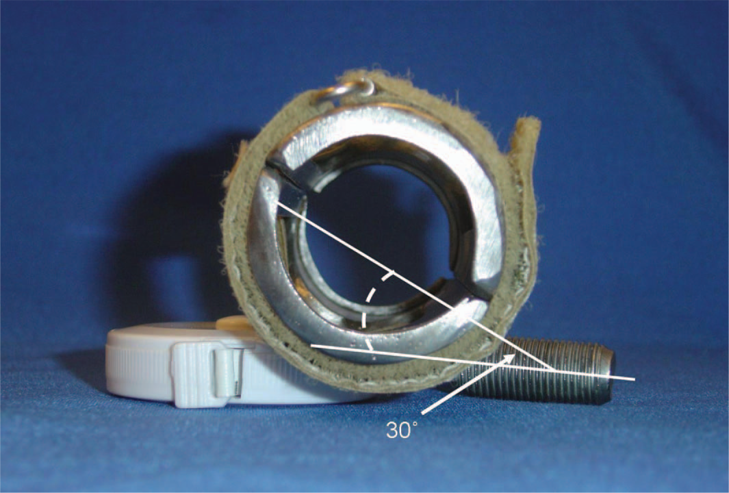
It was decided that the prehensor design was to be a cylinder (sleeve), within which the paddle shaft would be firmly housed, rotating within a cylinder (frame) and that common prosthetic materials were to be used to reduce cost and enhance reproducibility. The sleeve had to fit around a standard cylindrical kayak paddle shaft, measuring 27 mm outside diameter (o.d). Further, the length of the sleeve was defined to be the average width of a hand (measured from four adult subjects at the metacarpophalangeal joint line). A common, aluminum, lower extremity prosthetic pylon also measures 27 mm inside diameter (i.d) and 32 mm o.d and an 89 mm long section of this was cut to form the basis for the sleeve. The sleeve was longitudinally split in two pieces using a portable band saw (Figure 1). The two-piece sleeve was joined together using contact cement to attach non-slip netting (Dycem Ltd., Warwick, RI, USA), a high friction material that served both as a joint and surface to grip the paddle. A common soling material, Minicheck Topi Soling Material (1/16th inch (2 mm) black ‘cat's paw’), (SoleTech, Inc., Salem, MA, USA) was used on the inner sleeve surface opposing the non-slip netting to increase the friction of the paddle grip. The finished inner sleeve formed a single hinged cylinder that can be opened to allow the paddle to be acquired and strongly maintains a grasp, particularly when compressed.
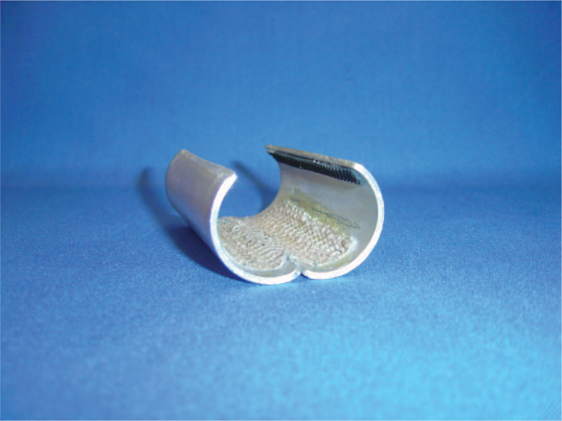
Completed inner sleeve that maintains contact with the paddle. An aluminum pylon was split into equal halves longitudinally. All edges were smoothed. Non-slip netting spans the two halves, serving as a joint and facilitating paddle grasp. Non-slip netting and Minicheck Topi soling material were secured to the sleeve's inner surface with contact cement.
In order to fulfill the functional requirements initially outlined, the frame needed to have a suitable i.d to permit free sleeve rotation when the paddle is in the sleeve. The frame also had to prevent the sleeve from accidentally opening and losing grip on the paddle and conversely be able to open for independent sleeve and paddle application. Additionally it required mediolateral stops (Figure 2) to prevent the sleeve and paddle from sliding out of one of the ends. Final considerations were that it should have provision for solid attachment in the defined initial wrist position, be lightweight, durable and made from a commonly found material. Standard size pipe (nominal 1¼ inch), a common product, was of the appropriate i.d. (33 mm). It is available in both aluminum and steel from local pipe suppliers throughout the US, either of which material would be suitable.
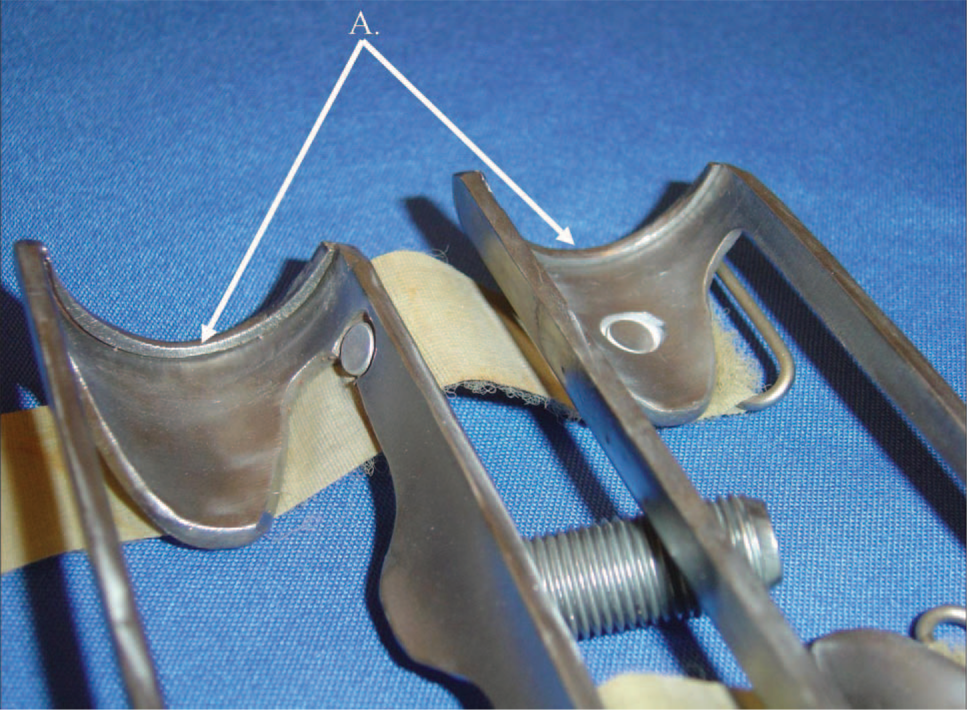
Completed frame showing the internal structure including mediolateral stops (A). Washers were welded into the ends of the frame to make the end stops. Excess material was ablated until the kayak paddle would clear the stop.
Steel pipe was selected for the prototype for initial design, redesign and evaluation. The pipe section used for the frame was cut 6 mm longer than the sleeve to provide slight mediolateral tolerance and space to weld mediolateral end stops into the frame. The pipe was cut into two longitudinal pieces and the abrasive inner surface was smoothed (Figure 3).
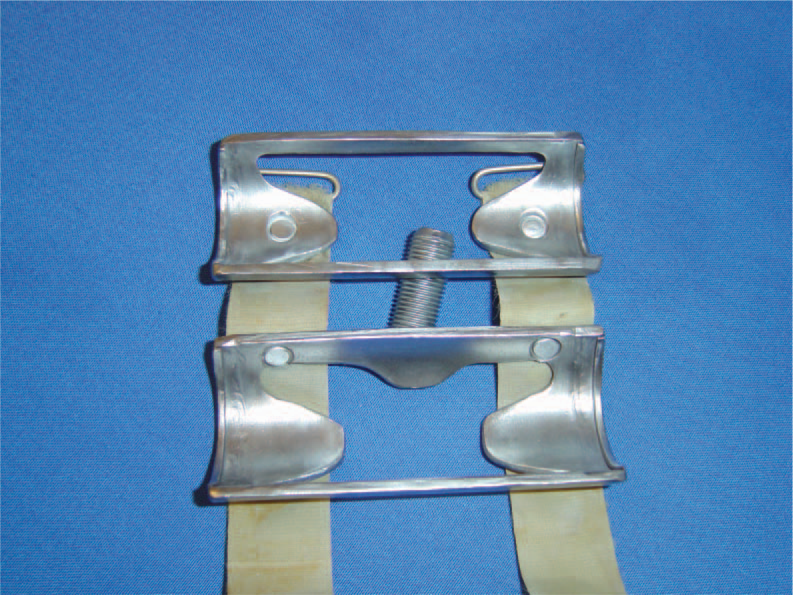
The complete external frame from an inside viewpoint. Rivets securing the Velcro closure straps were countersunk to prevent contact with the inner sleeve during rotation of the paddle. Large ‘windows’ were cut in the steel prototype's frame to reduce mass and potentially reduce friction between the frame and inner sleeve.
Mediolateral stops were fabricated using two steel washers, cut into halves. Each of the four pieces of washer was welded into the pipe, flush with the end of the frame. Excess material was ablated using a Dremel Tool (Dremel, Racine, WI, USA) until closing the frame halves permitted the paddle and sleeve to be captured in the frame while permitting rotation (Figure 2).
The wrist attachment bolt was then welded to the lower frame section in the previously described initial position. A standard ½ inch × 20 thread per inch bolt was used as this is the standard thread for common wrist units such as the Hosmer 52147 (Hosmer, Campbell, CA, USA) (Figures 4 and 5). Pronation and supination of the TD relative to the forearm were achieved by allowing the attachment bolt to rotate within the wrist unit. During kayaking, with both upper extremities grasping the paddle, a full rotation of this articulation is not permitted. Therefore, if the attachment bolt is turned into the wrist unit a sufficient number of rotations, the limited rotation needed during paddling poses a negligible risk of the prehensor losing attachment with the wrist unit.
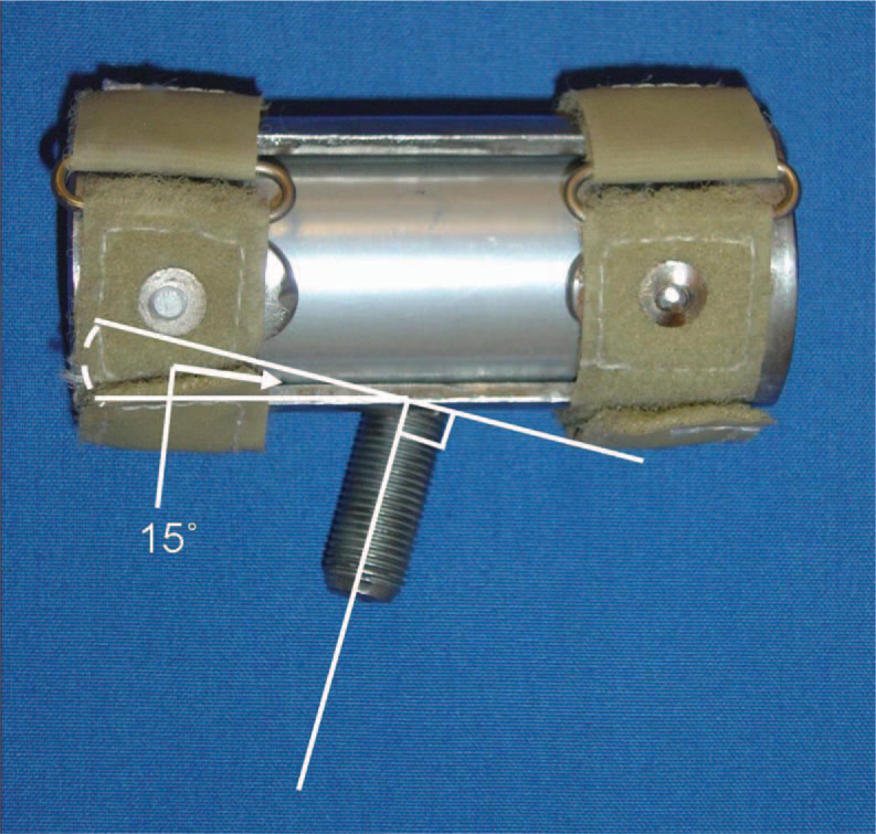
Frontal plane (superior) view of the frame, demonstrating 15° of pre-positioning the hand frame into radial deviation relative to the wrist attachment bolt. Straps were made from 19mm (3/4 in) non-adhesive hook and loop strapping with 1 inch (25 mm) × 3/16 inch (5 mm) stainless steel loops sewn into one end of each strap.
Sagittal Plane (lateral) view of a Right hand demonstrating 30° of pre-positioning the hand frame into wrist extension relative to the wrist attachment bolt. The head of the bolt was removed allowing more surface contact between the bolt and frame for welding fixation.
Following attachment bolt fixation, all surfaces of the inner sleeve and frame were buffed, smoothed and sand blasted. The final step in fabricating the hand was to make closure straps. Straps were made from non-adhesive hook and loop strapping material (Velcro USA, Inc., Manchester, NH, USA) and were secured to the frame utilizing rivets countersunk into the hand frame (Figures 3 and 4).
The pseudo-prosthesis
In order for the non-amputee subject to use the USF Kayak Hand to simulate paddling in the laboratory setting, it was necessary to build a pseudo-prosthesis incorporating a prosthetic wrist unit. Using a design adapted from Lake, 8 a two-stage impression was taken of a participant's left upper-extremity. From the impression, a model was created and appropriately modified. A thermosetting socket was fabricated over the model that incorporated a standard friction wrist unit (Hosmer 52147). The anatomic wrist was in a comfortable, neutral position and a handle was provided in the palmar surface of the hand; all incorporated into a single stage lamination. Large relief windows were cut into the radial and ulnar surfaces of the socket to avoid the socket clashing with the styloid prominences during motion and to permit comfortable donning and doffing.
Results
Following fitting and adjustment of the pseudo-prosthesis, the non-amputee participant was able to independently apply the hand to the paddle (Figure 6) and successfully simulate paddling in the laboratory setting and in a swimming pool (Figure 7). A preliminary motion study was conducted. 7 There were no reports of obvious movement restrictions at any joint and the hand permitted paddle rotation without loss of grasp.
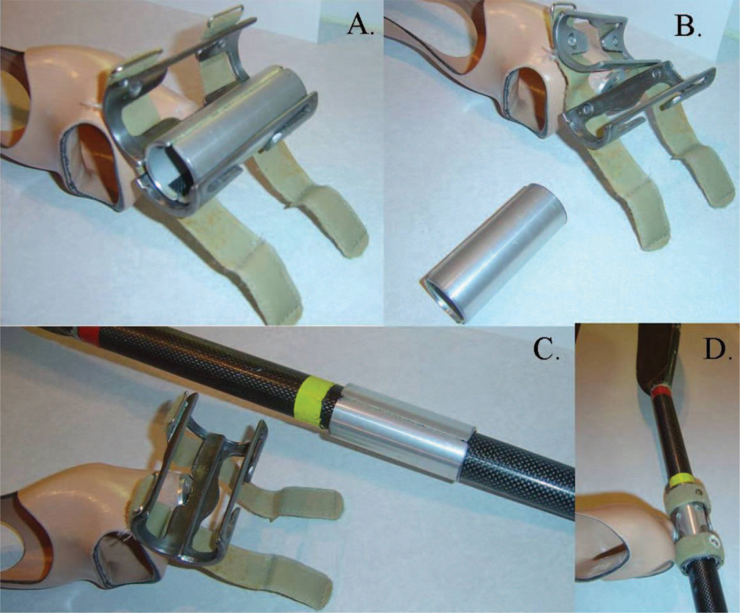
Steps to apply USF Kayak Hand to paddle. Open closure straps to expose and remove inner sleeve (steps A & B). Open sleeve and apply to paddle at desired location (step C). Replace sleeve in frame and secure closure straps (step D).
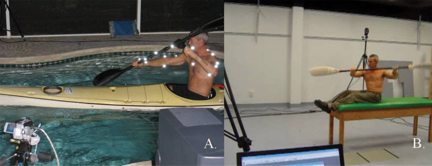
Simulated kayaking in a pool (A) and on a mat table (B).
Subsequently, a client with a left transradial amputation without previous kayak experience was trained by a certified instructor on a slow-moving river (Figure 8). The client was able to self-propel the boat with a style similar to a novice kayakist.
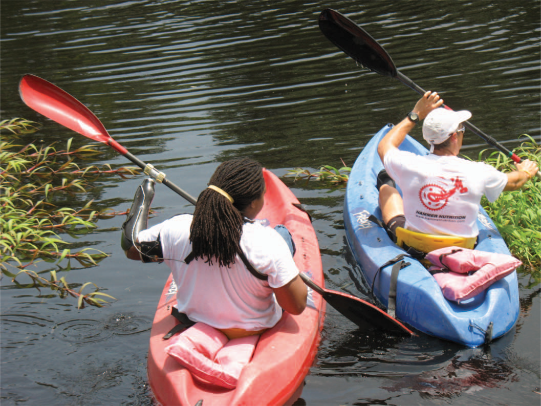
Individual with transradial amputation kayaking under close supervision with an expert instructor.
The design was casually tested in two other situations requiring cylindrical grasp: Sweeping and hand held exercise weights. In both cases, the participant using a pseudo-prosthesis could complete the activity.
Discussion and conclusions
There are several promising aspects of this device that warrant further study. For kayaking, it offers excellent grasp with relatively unhindered paddle rotation. If fabricated from different materials, it could be an extremely durable and lightweight TD. The USF Kayak Hand may have application in other upper extremity tasks that require a stable, passive, cylindrical grasp. Weight lifting and sweeping are two examples (Figure 9) but other repetitive activities requiring cylindrical grasp should also be considered and tested.
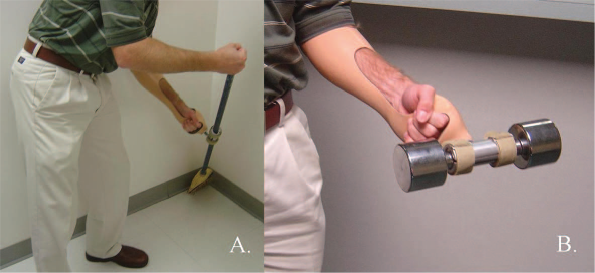
USF Kayak Hand attached to a broom (A) and a 5 lb hand weight (B). Because the diameter of the broom handle and weight are different than a kayak paddle, a ¼ inch (6 mm) thick piece of foam was placed on the handle prior to hand application. In the case of weight lifting, the wrist unit may need to be locked or tightened to prevent pronation/supination whereas with sweeping and kayaking, free pronation/supination may be desirable.
Investigators required this preliminary testing in order to proceed with IRB approval and to substantiate the need for further evaluation. Detailed kinematic analysis and comparison to both a commercially available product and to the non-prosthetic, expert kayak stroke are published elsewhere. 7
Limitations of this prototype include the fact that steel corrodes in the presence of moisture and is heavy compared to aluminum or thermoplastics. The fact that this device has a removable inner sleeve could pose issues in terms of losing the sleeve during on-water application and with gadget tolerance compared with the commercially available one piece design. Finally, the prototype required welding to fabricate, which is a skill not available in all prosthetic laboratories.
The authors of this work advise conducting a risk assessment and consultation with component manufacturers prior to undertaking the fabrication of custom-made devices. This would assist in determining if a commercial product is available and whether or not the benefits outweigh the risks of utilizing a custom fabricated device.
Footnotes
Acknowledgements