
Abstract
This paper presents the results of preliminary walking experiments on a transtibial amputee wearing a powered prosthesis. The prosthesis prototype serves as a proof-of-concept implementation for investigating the potential of pleated pneumatic artificial muscles to power a transtibial prosthesis. The device is equipped with pleated pneumatic artificial muscles, and tethered to a laboratory pressure source. The prosthesis is capable of providing the amputee with 100% of the required push-off torque and it can adapt its joint stiffness to the walking speed. This study supports the hypothesis that a powered transtibial prosthesis with adaptable stiffness might be beneficial to the amputee.
Introduction
Numerous prosthetic feet have been developed during the past decades. Besides the aesthetics of the prosthetic foot itself, more attention has been given to restoring able-bodied ankle behavior. Particularly, the ‘push-off’ occurring in late stance is partially recovered by using ‘energy-storing’ materials. The concept of an ‘Energy-Storing-and-Returning (ESR)’ foot was met with great interest and soon became a driving force in the development of prosthetic feet. Transtibial (TT) amputees feel an extra force in late stance and describe a feeling of buoyancy when fitted with an ESR foot. 1 It was claimed that ESR feet would reduce the metabolic energy cost and increase mobility. However, despite the technological progress during the past decades, researchers have shown that the ESR feet currently available have neither reduced the metabolic energy cost of walking nor brought significant enhancements in the amputee's gait pattern. 2,3 New prosthetic feet equipped with active components might better restore able-bodied ankle behavior, resulting in more efficient amputee gait.
A major contribution to the research on powered prostheses comes from the Massachusetts Institute of Technology (MIT) Media Laboratory. A powered prosthetic foot, capable of mimicking normal ankle behavior, was developed by Au et al. 4–6 The system uses a combination of a spring and a ‘Series Elastic Actuator (SEA)’. 7 A peak torque output of 140 Nm was achieved. Given its favorable performance properties, Au et al. strongly believe that their prosthesis might reduce metabolic energy cost and might allow a more natural gait.
Researchers at Arizona State University have built Sparky1, which is an acronym for Spring Ankle with Regenerative Kinetics. Sparky1 consists of a parallel two spring robotic tendon, attached to the leg and to a commercial keel via a lever arm. A RE-40 DC® motor (Maxon motor, Switzerland) is connected with the robotic tendon through a leadscrew mechanism. Hitt et al. 8 communicated – based on simulation results – that Sparky1 is capable of providing the amputee with 100% of push-off torque while maintaining gait kinematics similar to able-bodied gait.
Klute et al. 9,10 described the design of a muscle-like pneumatic actuator for a TT prosthesis. Based on simulation results, the prosthesis was expected to generate a high torque output (110 Nm) and allow for an ankle range of motion of 30 degrees. Despite these interesting performance characteristics, no published material – to the best of the authors' knowledge – on Klute's progress in developing the powered prosthesis could be found. Besides prostheses, pneumatic actuators have been applied in orthotic devices as well. In 11 , Gordon et al. address the mechanical performance of pneumatic artificial muscles to power an ankle-foot orthosis.
For the current study, a prototype of a TT prosthesis powered by pleated pneumatic artificial muscles (PPAMs) has been developed. The concept and working principle of PPAMs was discussed by Daerden and Lefeber 12 A torque output of 200 Nm can easily be achieved with a PPAM pressure of only 3 × 10 5 Pascal, which is comparable with the pressure inside a bicycle tire.
The use of PPAMs to power a TT prosthesis allows an active push-off and the adaptation of the prosthesis' stiffness according to the walking speed. The latter was not the case in any of the above described prosthetic feet and adds some new value to the state-of-the-art of TT prostheses. Hansen et al. 16 have shown that the prosthetic ankle stiffness changes with the walking speed and they reported that a prosthesis with adaptable ankle stiffness might be beneficial to the amputee. We, therefore, hypothesized that the development of a new prosthesis powered by PPAMs should better restore able-bodied ankle behavior and consequently enhance the walking performance in TT amputees.
Methods
Case report
The subject who participated in this study had a completely healed, unilateral TT amputation on the left side and was capable of independent ambulation. The subject was male, aged 58, 165 cm tall, 58 kg in mass and had a stump length of 20 cm. He underwent the amputation at age 44 as a result of trauma. He had been fitted with a Re-Flex VSP® foot (Össur, Iceland) and wore this prosthesis all day for his ordinary activities. He showed none of the medical obstructions to walking as indicated by Steinberg. 13 The walking experiments were carried out on a treadmill, the speed of which was controlled by an operator. Before testing, the subject became accustomed to treadmill walking at different speeds. During the experiments, two clinicians were present for prosthetic alignment and feedback on the amputee's gait. Ethics committee approval was obtained from the Brussels University Hospital (Universitair Ziekenhuis Brussel) and the amputee signed the informed written consent form.
Prosthesis description
The powered prosthesis was equipped with PPAMs. These actuators were desirable for our application because they were extremely lightweight, capable of generating high forces and inherently compliant. A photograph of an inflated state of a PPAM is given in Figure 1.
Photograph of an inflated state of pleated pneumatic artificial muscles (PPAM).
The pulling force generated by a PPAM is given by:
Since PPAMs can only generate pulling forces, at least two actuators needed to be coupled antagonistically in order to establish a bidirectional rotational motion (see for instance Figure 2).
Schematic view of an antagonistic setup with PPAMs.
Taking into account Equation (1) and if r
1 and r
2 define the leverage arm of the extensor and flexor PPAM respectively, the joint torque τ is given by the following expression:

A photograph of the prosthesis is shown in Figure 3. The prosthesis used three PPAMs, one was placed anteriorly and two were placed posteriorly. Each PPAM connected to the amputee's prosthetic socket (fabricated by the orthopedic team of the Pellenberg Rehabilitation Centre, Belgium). The other end was attached to an Axtion® foot (Otto Bock HealthCare, Germany).
Transtibial amputee fitted with the prosthesis prototype.
A quadrature AEDA 3300® encoder (Avago technologies, Germany) was mounted on the ankle joint to measure the joint angle, which was defined as zero when the plantar aspect of the prosthetic foot was perpendicular to the longitudinal axis of the prosthetic tube. Dorsiflexion (positive angles) and plantarflexion (negative angles) signified upward and downward motion of the foot, respectively. Three BSDX5000G2R® pressure sensors (Sensortechnics, Germany) measured the PPAM pressure. The sole of the prosthetic foot was equipped with three FlexiForce® footswitches (Tekscan, US). One footswitch was placed at the heel and detected the instance of heel contact. A second footswitch was placed at the forefoot (top of the toes) and was triggered just prior to toe-off. A third footswitch was placed in between the others and was triggered after midstance when the prosthetic foot was dorsiflexing. The prosthesis was tethered to a valve unit that was provided with pressurized air at a gauge pressure of 7 × 10 5 Pascal by a laboratory pressure source. The valve unit consisted of three KPS¾− 10® servo valves (Kolvenbach, Germany), which controlled PPAM pressure according to a set value that was provided as an analog voltage signal. The prosthesis prototype was connected to a multifunctional I/O DAQ board from National Instruments® that was interfaced with a PC.
Prosthetic ankle joint stiffness during walking
Figure 4A shows the hysteretic torque-angle curve (torque expressed in Nm per kg bodymass) of the human ankle for able-bodied walking at 1.5 m/s. The displayed curve was built from the combination of two datasets, extracted from Winter: 15 (i) Ankle torque versus time, and (ii) ankle angle (sagittal plane) versus time. Point A represents the instance of initial heel contact. In B, the whole foot sole touches the ground. Points C and D represent the instance of maximum ankle torque and toe-off, respectively.
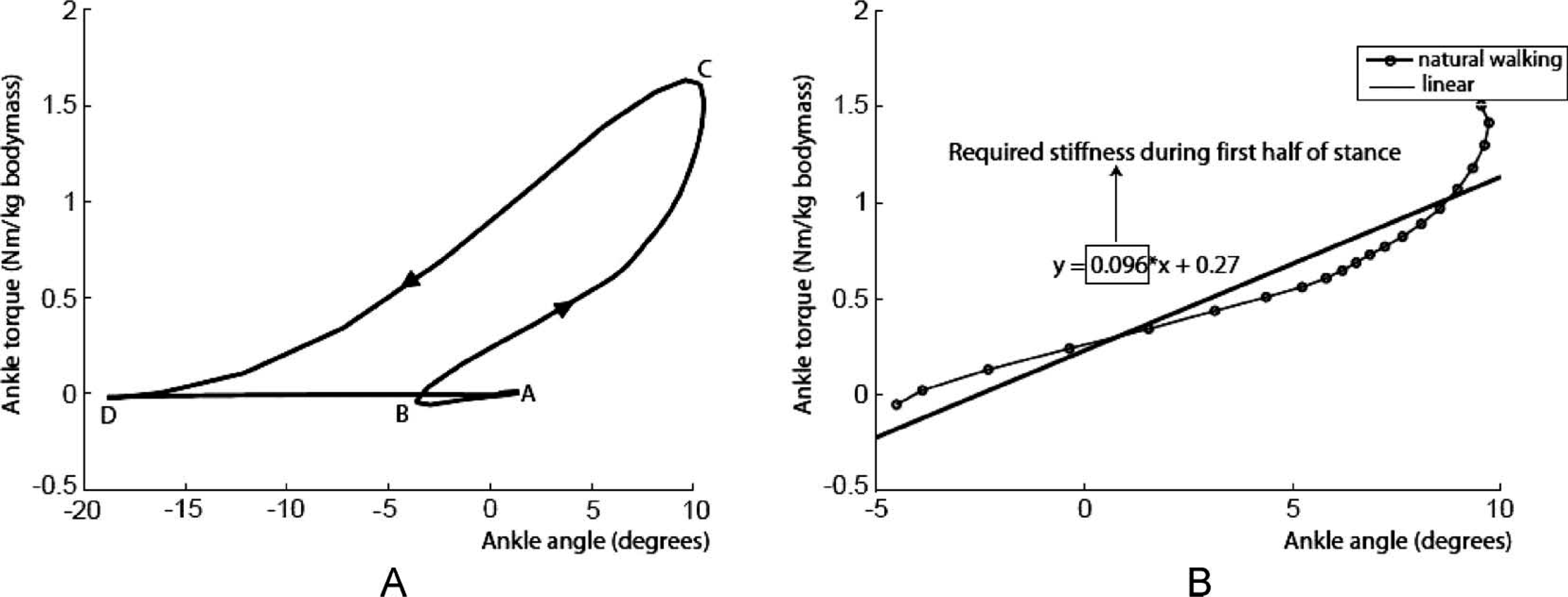
(A) Ankle torque versus ankle angle (sagittal plane) plot for walking at 1.5 m/s. Data originating from Winter. 15 Positive angles indicate dorsiflexion and negative angles indicate plantarflexion. Point A represents the instance of initial heel contact. In B, the whole foot sole touches the ground. Points C and D represent the instance of maximum ankle torque and toe-off, respectively. (B) Ankle torque plotted versus ankle angle (sagittal plane) for the first half of the stance phase (dotted line B–C). The slope of the straight line gives the required ankle joint stiffness during this part of stance.
Figure 4A is very useful for the development of new prosthetic feet as the slope of the plotted curve reveals the intrinsic stiffness of the human ankle in stance. Hansen et al. 16 reported that average ankle stiffness varies with changing walking speeds.
The prosthetic devices that were addressed in the introduction provided the amputee with 100% of push-off torque but did not change prosthetic ankle stiffness according to the walking speed. Bearing in mind the findings of Hansen et al., it was strongly felt that current and future prosthetic feet should be capable of changing their stiffness according to the walking speed.
The required stiffness during the preliminary walking experiments with our prototype was determined by performing a linear regression on the data of Winter. 15 Figure 4B gives Winter's data of the ankle joint during the first half of stance, which is a part of the curve shown in Figure 4A. Linear regression on these data resulted in an ankle joint stiffness of 0.096 Nm/(kg bodymass∗degrees). A linear regression on the data of the second half of the stance phase (not shown in Figure 4B) resulted in a joint stiffness of 0.068 Nm/(kg bodymass∗degrees). Consequently, we used the average of both slope coefficients, being 0.082 Nm/(kg bodymass∗degrees) as prosthetic ankle joint stiffness for normal walking. Performing a linear regression on Winter's data of slow and fast walking (not shown in the figure) resulted in the average stiffness values of 0.083 and 0.12 Nm/(kg bodymass∗ degrees), respectively. Finally, because the stiffness values for slow and normal speed were nearly the same, a trade-off was made to use only two overall prosthetic ankle joint stiffness values (0.082 and 0.12 Nm/[kg bodymass∗degrees]), corresponding to a pressure in each PPAM of 0.3 × 10 5 Pascal and 0.8 × 10 5 Pascal at zero ankle angle, respectively.
Generating torque during walking
As the amputee who participated in our study weighed 58 kg, this therefore resulted in a maximum ankle torque of about 100 Nm for normal walking (see Figure 4A). In order to apply this torque, a PPAM pressure of 1.5 × 10 5 Pascal is required, which is relatively low. We decided to adopt a simple feedforward approach to generate the high torque, rather than developing advanced control algorithms. The following is meant with ‘feedforward’. Prior to the walking experiments, the desired torque values were converted to PPAM pressures and the corresponding input voltage signals for the pressure servo valves were calculated. Whenever torque was required during walking, we applied the calculated input voltage signals to the servo valves. We did not use a torque feedback signal to accurately control the exact torque exerted by the prosthesis.
The prosthesis works as follows: After heel contact, it waits for the foot dorsiflexion to reach a threshold angle of 10° for self-selected walking and 5° for fast walking (1.8 m/s) before initiating push-off torque generation. Torque is then generated by increasing the gauge pressure in both posterior PPAMs to 1.5 × 10 5 Pascal (corresponding to an ankle torque of 100 Nm), while the pressure in the anterior PPAM is decreased to zero (to avoid it counteracting the posterior PPAMs). The torque causes the prosthetic foot to plantarflex which is experienced as ‘push-off’ by the amputee.
After toe-off, increasing the pressure in the anterior PPAM and decreasing it in the posterior PPAMs dorsiflexes the foot to avoid the drop foot effect. After this dorsiflexion, all PPAMs are brought back to the same gauge pressure, which is needed to set the prosthesis' stiffness to the desired value in anticipation of the next heel strike.
Results
In the first walking experiment, the subject was asked to walk at his self-selected speed, which proved to be 1.3 m/s. At this walking speed, the prosthesis' stiffness was set to 4.76 Nm/degrees (0.082 Nm/[kg bodymass∗degrees] ∗ 58 kg).
Figure 5A displays angular data for self-selected walking. At this walking speed, approximately three steps were taken during a time frame of eight seconds. After heel contact, the prosthetic foot plantarflexed to −2.5°. Then, a dorsiflexion of 10° was reached and, at toe-off, the prosthetic ankle plantarflexed to −12°. During swing, the foot was dorsiflexed to avoid a drop foot effect.
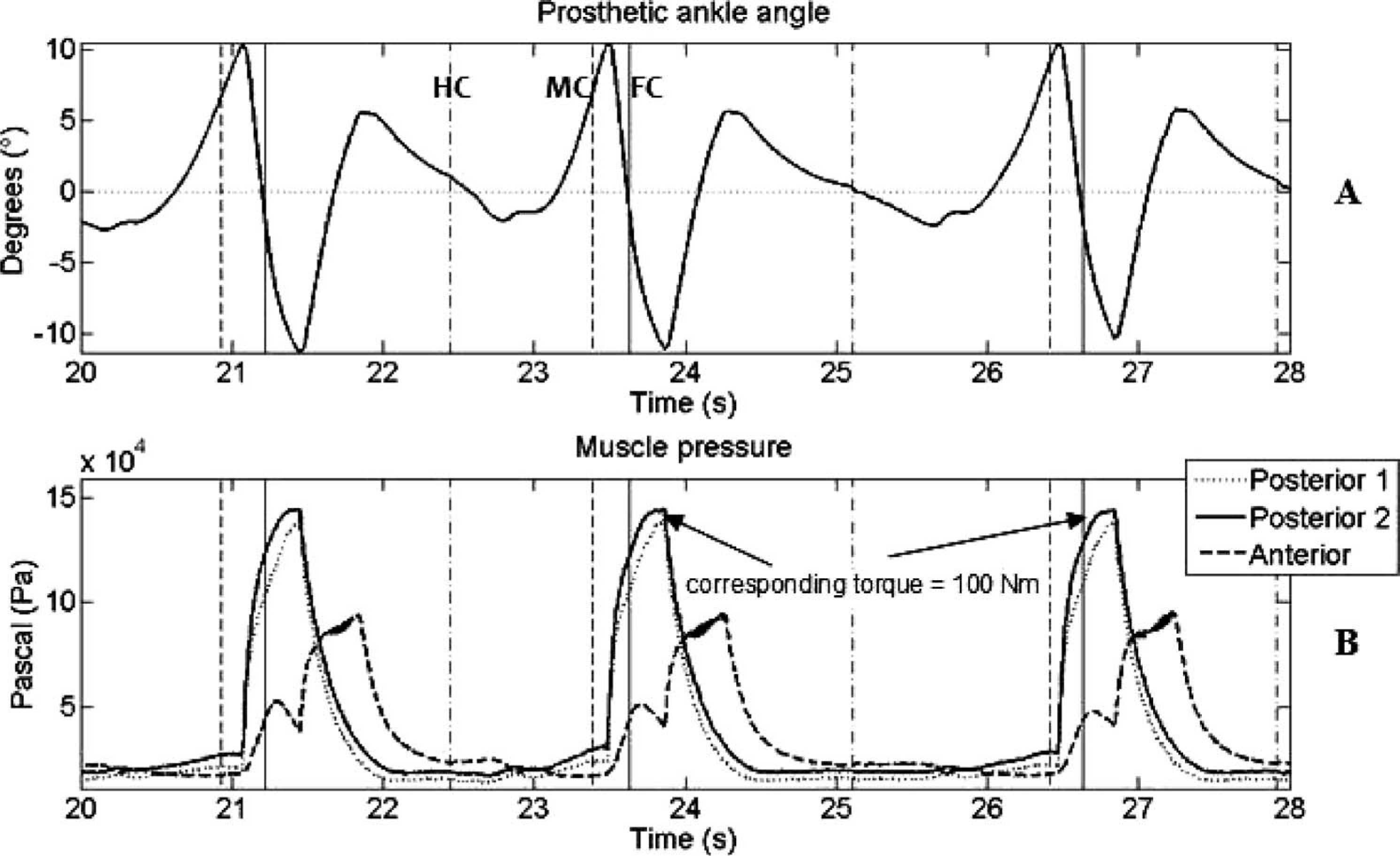
Results of walking at 1.3 m/s. (A) Angle of the prosthetic ankle joint (sagittal plane) plotted versus time (positive angles indicate dorsiflexion and negative angles indicate plantarflexion). (B) PPAM pressures plotted versus time. The vertical lines that are dashed-dotted, dashed and solid represent heel contact (HC), midfoot contact (MC) and forefoot contact (FC), respectively.
Figure 5B displays the pressure in each PPAM. Between heel contact and midfoot contact, the prosthetic foot first plantarflexed and then dorsiflexed (to ∼ 7°) while the PPAM pressures did not change significantly. Just after midfoot contact, there was an increase in PPAM pressure. The peak pressure corresponded with peak plantarflexion (−12°) just after toe-off. Pressures of 1.5 × 10 5 Pascal (solid and dotted lines) were applied to achieve a 100 Nm torque output. Immediately after toe-off, pressure was applied to the anterior PPAM (dashed line) in order to bring the foot back in dorsiflexion so that a drop foot effect was avoided. During swing, the PPAM pressures were kept at 0.3 × 10 5 Pascal, which gave a stiffness of 4.76 Nm/degrees.
Figure 6A and 6B show the angular data and pressure data of walking at 1.8 m/s, respectively. During these walking experiments, the prosthesis' stiffness was set to 6.96 Nm/degrees. The maximum dorsiflexion angle was 5°. Compared to the 1.3 m/s walking trial, about two more steps were taken within the same time period, resulting in a shorter stance phase. As was the case in the 1.3 m/s walking trial, the PPAM pressures did not change significantly between heel contact and midfoot contact. The initial offset pressures during this walking experiment were higher (0.8 × 10 5 Pascal instead of 0.3 × 10 5 Pascal) because of the higher stiffness.
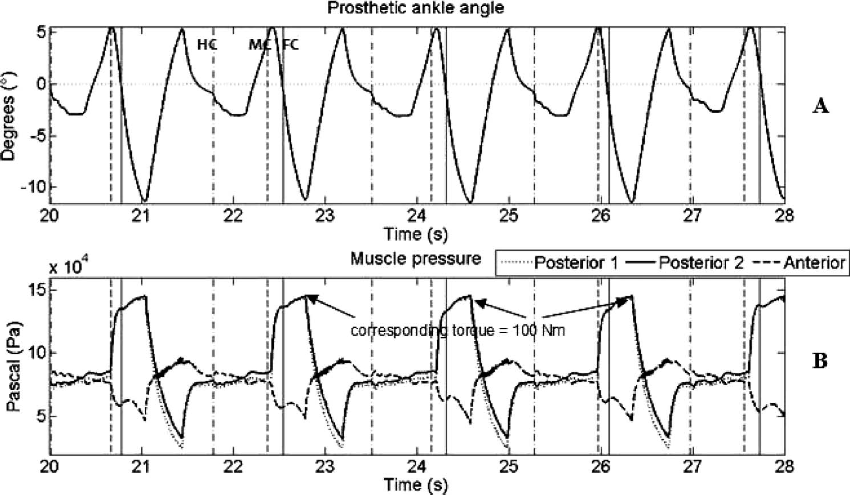
Results of walking at 1.8 m/s. (A) Angle of the prosthetic ankle joint (sagittal plane) plotted versus time (positive angles indicate dorsiflexion and negative angles indicate plantarflexion). (B) PPAM pressures plotted versus time. The vertical lines that are dashed-dotted, dashed and solid represent heel contact (HC), midfoot contact (MC) and forefoot contact (FC), respectively.
Discussion
This paper reports the results of preliminary walking experiments on a TT amputee, fitted with a powered prosthesis. The amputee walked at different speeds and the prosthesis generated the adequate torque output. The prosthesis' stiffness was changed according to the walking speed. Two prosthesis' stiffness values were used; one for walking at self-selected speed (1.3 m/s) and one for walking at 1.8 m/s. The latter walking speed was chosen in agreement with the amputee. It was the highest walking speed at which the amputee still felt safe and comfortable.
Figure 5A demonstrates that the able-bodied averaged ankle range of motion – as published by Winter 15 and Perry 17 – can be achieved properly with the prosthesis prototype. Figure 5B gives the pressure in each PPAM. After heel contact, a small increase of the anterior PPAM pressure can be seen. This is due to the decreasing volume of this PPAM as it is stretched during the phase ‘heel contact→foot flat’. This behavior is similar to that of the human ankle dorsiflexors during the phase ‘heel contact→foot flat’.
In the beginning of the 1.8 m/s walking trial (Figure 6), the same angle of 10° was used as a trigger for the instance at which torque was generated. However, after some steps it was seen that the subject could not reach this angle due to the higher ankle joint stiffness. Consequently, the threshold angle value was decreased to 5°. This clarifies that the maximum dorsiflexion angle is 5° for the faster speed (see Figure 6A). Despite the fact that the prosthetic foot plantarflexed to −12°, the dorsiflexion of the foot was unsatisfactory, and this needs further attention.
The initial walking experiments were conducted on one amputee. The results of this study are encouraging as the prosthesis is capable of providing the amputee with 100% of push-off torque and changing its ankle stiffness. Moreover, the amputee's evaluation of the first walking experiments was promising. He felt safe and comfortable while walking with the prosthesis and he reported that the extra force (torque) generated by the PPAMs was beneficial. Further research is required on a larger group of subjects with performance metrics to assess the performance and benefits of the prosthesis.
The presented proof-of-concept prosthesis was tethered to a laboratory pressure source and served as a test bed. The principal aim of this study was to investigate whether PPAMs are promising actuators to power a lower-limb prosthesis. Aspects such as pneumatic power generation and autonomy – i.e., meaning that the device could be disconnected from the pressure source for independent use – were not investigated in this study, but will be the subject of further research. The next prototype should be untethered and thus, self-powered. Calculations indicate that, in the current prototype, a system's autonomy of over 2 h of continuous walking – outside the laboratory – can be guaranteed when using a 600 W compressor (assuming an isentropic efficiency of 70% and a motor efficiency of 90%) and a 2 kg Li-S battery pack with an energy density of 600 Wh/kg. The liquid-fueled approach, described by Fite and Goldfarb 18 and Shields et al., 19 will be considered as well. The aforementioned publications describe pneumatic actuators, which are powered by the reaction products of a catalytically decomposed liquid monopropellant. The proposed approach has been experimentally shown to provide an order of magnitude greater actuation potential than state-of-the-art batteries and motors. Furthermore, passive elements (springs) will be incorporated in the next prototype. The latter will allow decreasing the size of the PPAMs dramatically, resulting in a lower weight and a higher degree of autonomy. Finally, another item that should be assessed when utilizing the prosthesis outside of the laboratory is the issue related to automatically changing the stiffness as walking speed changes. During this preliminary study, the device was set prior to the walking trials at constant speed; but in order for this technology to be applied outside the laboratory, it will need to automatically change stiffness values as walking speed varies. Possible strategies to approach this issue are to use the angular encoder data (angular velocity) or the time delay between two heel contacts to determine the amputee's walking speed and to set the desired ankle stiffness by changing the PPAM pressures. However, these approaches were not yet investigated and are subjected to further research.
Conclusions
The results of this study reveal that PPAMs are promising actuators for powering a transtibial prosthesis. The amputee was provided with 100% of push-off torque during walking on a treadmill.
It is not easy to draw a far-reaching conclusion from one case report and further investigation on a larger group of subjects is needed to assess enhanced walking performance when using a prosthesis powered by PPAMs. Since PPAMs have interesting properties (high force-to-weight ratio, inherent compliance), their application is not restricted to prosthetics. Orthotic devices and exoskeletons could also benefit from the application of PPAMs.
Footnotes
Acknowledgements