
Abstract
This article proposes a type of transtibial socket composed of an inner layer fabricated by a rapid prototyping (RP) machine and an outer layer coated with unsaturated polyester resin. This work integrates contemporary technologies including a handheld scanner and CAD systems, to design a thin primary socket shape and then manufactures the socket using a fused deposition-modeling machine. To prevent breakage caused by the layer-based forming process and to reinforce flexural strength, the current research coats the preliminary RP socket with a layer of unsaturated polyester resin. After shaping the proximal brim of the resin-reinforced RP socket to match the specific stump, this study assembles and aligns a shank and a prosthetic foot to form a prosthesis set. After completing a trial safety walk wearing the prosthesis, which is satisfactory to the amputee and a registered prosthetist, this research measures interface pressures between the stump and the resin-reinforced RP socket. Experiment results demonstrate that the resin-reinforced RP socket is applicable for transtibial amputees. In addition to strengthening the FDM socket and producing consistent socket fit, this study also demonstrates a feasible procedure that employs current technologies to design and manufacture transtibial sockets without plaster moulds.
Introduction
A prosthesis is an artificial device that aids an amputee to recover partial functions of lost limbs. Experienced prosthetists currently dominate prosthetic socket fabrication. For a below-knee (BK) prosthesis, the manual process (Figure 1) for producing a new socket includes duplicating the residual limb shape using a plaster cast and modifying the shape of the plaster mould to meet the load-bearing ability of the specific amputee. The modified cast then becomes the basis for the socket, fabricated of either sheet thermoplastic material, such as polypropylene (PP) or a traditional lamination method, such as infiltrating unsaturated polyester resin (UPR) on cotton socks. The conventional plaster-based process manufactures excellent fitting sockets. The manual skills process also produces bad fitting sockets from case to case, resulting in user dissatisfaction from a poor quality prosthesis. To overcome manual method drawbacks, researchers have used CAD/CAM 1,2 and rapid prototyping technologies 3,4 to fabricate prosthetic sockets and have successfully demonstrated their research results. The benefits of using the CAD system and RP technology instead of the plaster-based technique include:
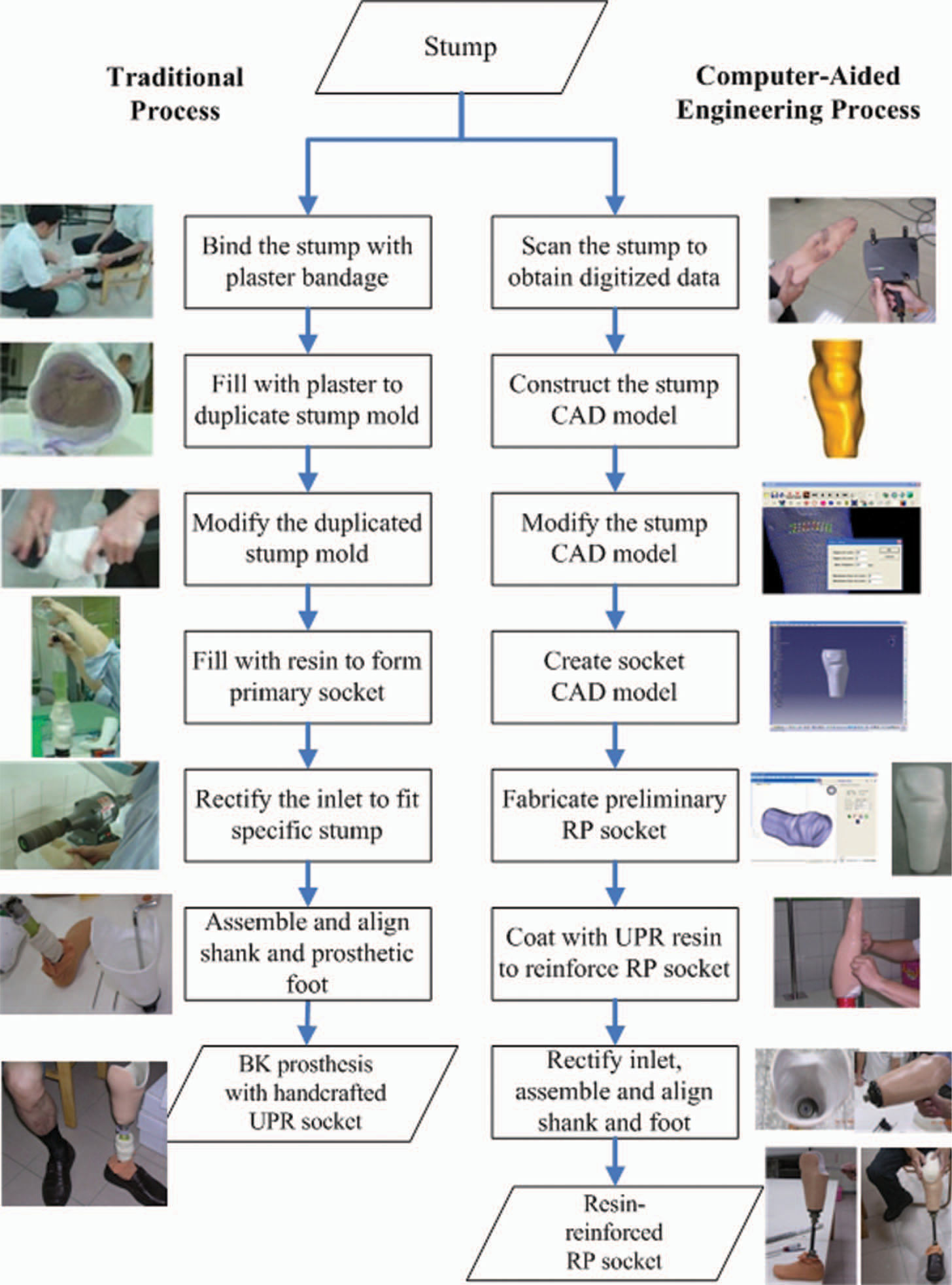
Process comparison between traditional and CAE methods.
Reducing professional dependency.
Producing more consistent socket fit.
Providing more flexibility for easily reversible changes in the rectification process.
Allowing future reproduction of a replica socket if needed.
Improving the work environment of the plaster-based process and eliminating plaster mould disposal.
Since the emergence of rapid prototyping technology, researchers have designed and fabricated a variety of prosthetic sockets using various types of RP machines 4,5 that include stereolithography (SLA), selective laser sintering (SLS), fused deposition modeling (FDM), and droplet/binding. Rovick et al. 6 at Northwestern University employed an SLA machine to make a transtibial socket. Researchers later fabricated a single transtibial prosthesis using the Squirt Shape system, 7 an in-house manufacturing process based on FDM technology. Three transtibial amputees used the Squirt Shape sockets for clinical trials. An active patient used one of the sockets for nearly three years. Rogers et al. 4 at the University of Texas at Austin in collaboration with the University of Texas Health Science Center at San Antonio developed advanced RP sockets, such as sophisticated doubled-wall and flexible wall sockets with compliant features, using an SLS machine. A number of amputees used these sockets for clinical acceptability evaluation and long-term durability tests. To employ SLS technology versatility, studies are investigating a novel construction stage for selective flexibility control to achieve better fitting sockets more easily fabricated using SFF (solid freeform fabrication) technology. Goh et al. 8,9 at the National University of Singapore developed a rapid socket manufacturing machine (RSMM) based on the FDM process which fabricates prosthetic sockets using polypropylene 4-mm filament. This research group uses RP technology to replace the tedious, labor-intensive procedure of conventional socket fabrication. Clinical and biomechanical assessments verify the comfort and fit of RSMM sockets. 3
Although researchers have employed RP technology to develop prosthetic sockets for nearly two decades, the prosthesis industry is yet to adopt RP sockets. Possible reasons may include quality uncertainty, such as socket strength, 3,10 and fabrication and technology cost barriers experienced by clinical professionals. 4 The literature has not reported commercialized integrating systems such as RSMM and Squirt Shape. Rogers et al. 4 commented that manufacturing RP sockets is not as large an issue as the existing service bureau infrastructure. The lack of available CAD systems for designing prosthetic sockets is a manufacturing barrier. In the review of Fuh et al. 3 it was suggested that building the prosthetic socket using fiber-reinforced resin may increase the strength and toughness of RSMM sockets. Herbert et al. 10 at Strathclyde University in Scotland, UK, developed a 4 mm-thick RP transtibial socket in which they wrapped a resin-reinforced carbon fiber layer to improve the limited strength for bearing amputee weight. This investigation demonstrates that the use of a cheaper, low-end RP technology, such as 3-D printing or the droplet/binding process, can be an alternative means to fabricate prosthetic sockets. A collaborative project 11 at National Cheng Kung University and Fooyin University in Taiwan developed a plaster-free process, finding that a socket with wall thickness of 4 mm solely fabricated by an FDM machine is vulnerable to breakage (Figure 2).
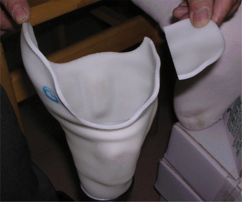
Breakage of an RP socket along the forming layer.
Because RP socket quality is the most important required property, such as socket strength, to avoid abrupt collapse while using the socket, this study focuses on strengthening and verifying the RP socket. Based on the traditional lamination method of infiltrating resin into cotton socks, this article proposes that a resin layer wrapped over a 2 mm-thick RP socket increases RP socket strength and shortens RP fabrication time, using less RP material. This paper also reports the process it develops to support fabrication of the proposed RP socket.
Methodology
Based on the concept of reverse engineering, 5 this study integrates contemporary computerized systems to formulate a computer-aided procedure (Figure 1) that enables researchers to design and manufacture a transtibial socket without using plaster casts. This work therefore develops a process to fabricate prosthetic sockets using an RP machine, and wraps the preliminary thin RP sockets in a layer of fiber-reinforced resin to increase socket strength. This process is briefly described as the following steps.
Scan the stump to obtain digitized data: This research employs a portable handheld scanner 12 to capture the stump shape of an amputee. After the set-up of the scanning system is organized, the patient firmly holds the stump while being scanned as the first step of the computer-aided engineering process shown in Figure 1. The scanned data of the stump shape will then be used for the next step.
Construct the CAD stump model: This study constructs a CAD model of the original stump (Figure 3a) using the scanned points. This step screens abnormal points and utilizes an in-house interface system
13
to build a mesh-model. The initial CAD stump model becomes the preliminary shape for designing the socket and analyzing its interface stresses.
Shape modification during socket design.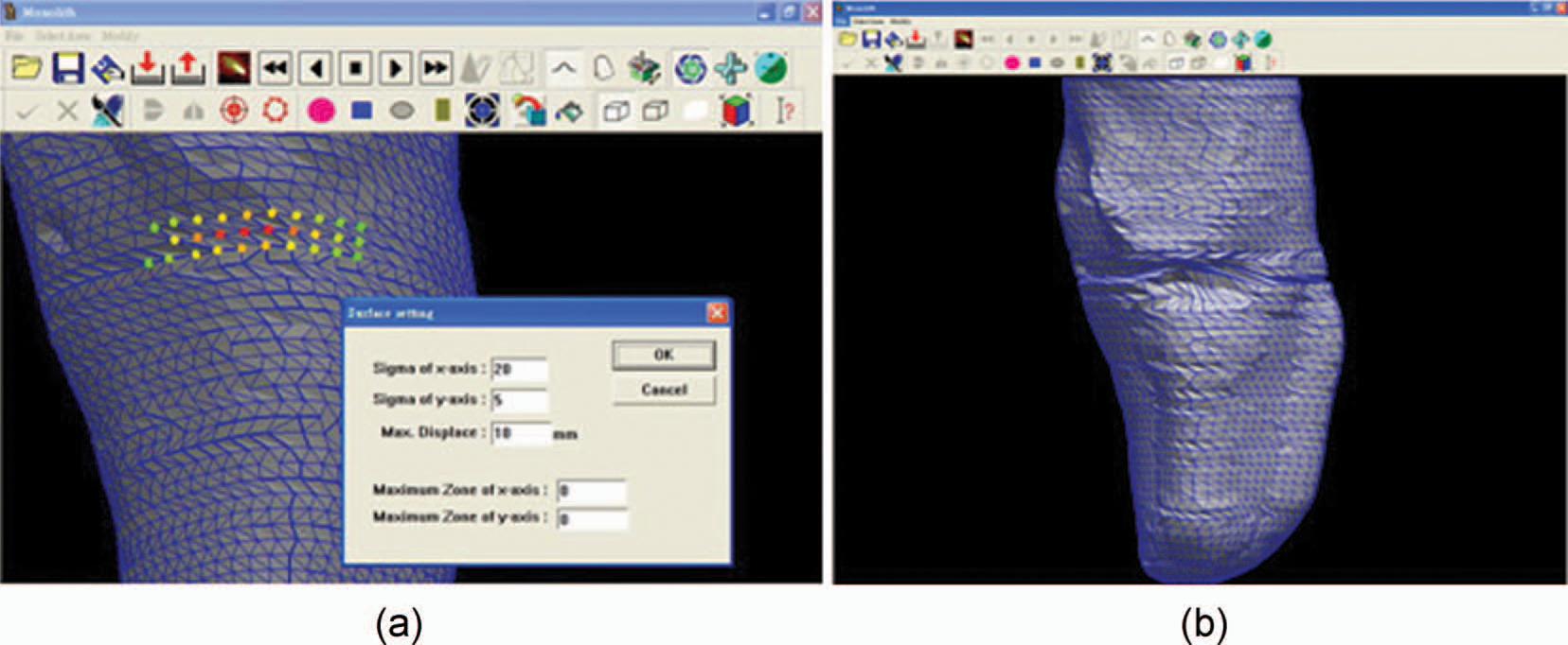
Modify the CAD stump model: The pressure relief (PR) areas of the stump model move outward and pressure tolerant (PT) areas indent inward based on prosthetic socket design principles. 14 Using the same in-house system employed in the previous step, shape modification proceeds iteratively until the modified areas reach a satisfactory level based on the prosthetist's judgment. This study then uses the modified stump shape (Figure 3b) to design a socket for the specific amputee.
Create socket CAD model: This step generates a CAD model so that the RP machine can fabricate a socket. Accommodating a liner or socks covering the stump to absorb friction and pressures directly exerted on the residual limb requires a gap of 4–7 mm. Therefore the geometric shape of the prosthetic socket must be larger than the stump. Using the modified stump surface model designed in the previous step, a CATIA system carries out offsetting, shelling and extending the length at the end of the modified stump model to meet the amputee's requirement. The method then acquires a designed socket model with 2 mm thickness (Figure 4a) and transfers its data in STL format to an RP machine.
A socket CAD model, its preliminary RP socket and infiltration of the resin-layer.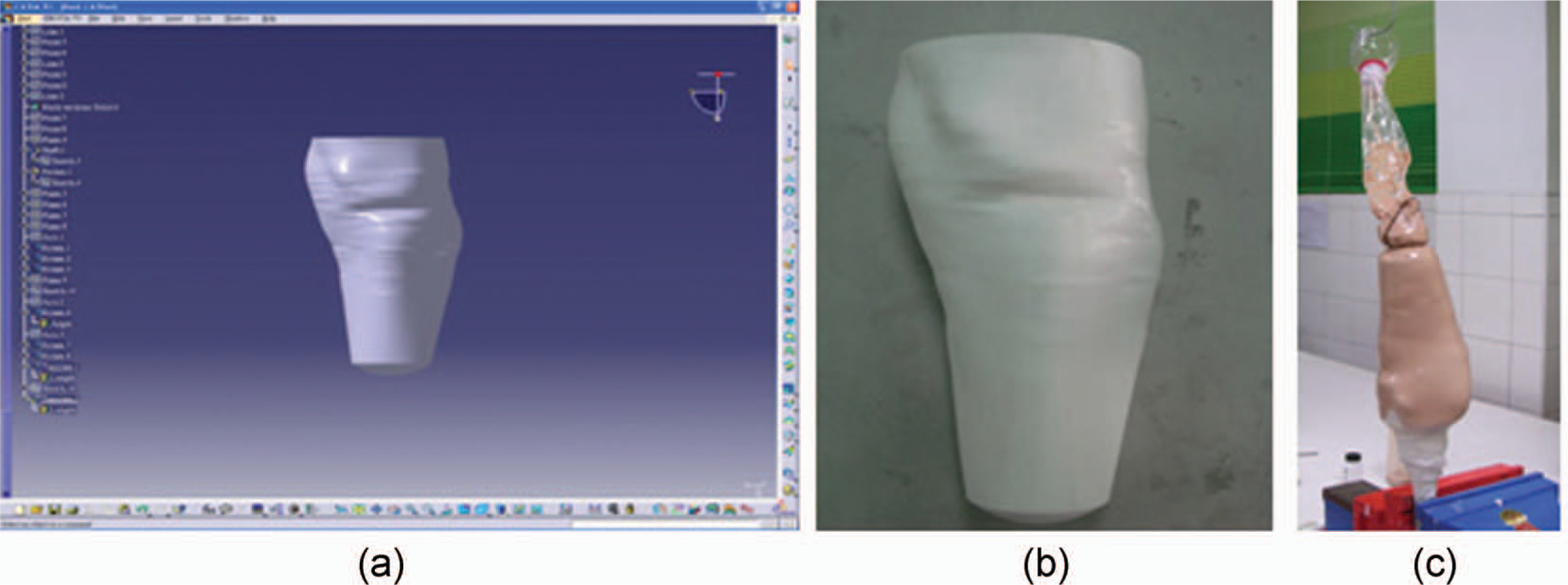
Fabricate preliminary RP socket: This study chooses an FDM machine, and designates polycarbonate (a widely adopted RP material) to form a preliminary RP socket as Figure 4b shows.
Coat with UPR layer to reinforce RP socket: After covering the preliminary RP socket with several layers of cotton socks, the procedure mixes liquid UPR with a hardener and then fills and uniformly squeezes the liquid by hand around the socket to allow UPR to infiltrate into the socks' fiber layers (Figure 4c). This step uses a vacuum pump to continuously keep the lamination and curing process going for 3 h. The procedure then dismantles the preliminary RP socket coated with resin layer for the following step.
Rectify inlet, assemble and align shank and foot: The proximal brim of the resin-reinforced RP socket is manually trimmed to allow the stump to insert into and fit the socket (Figure 5). This manual skill is exactly the same as that required by the traditional method and is the final step to acquiring a socket that fits the stump.
Trimming the proximal brim, assembling components and fitting the stump.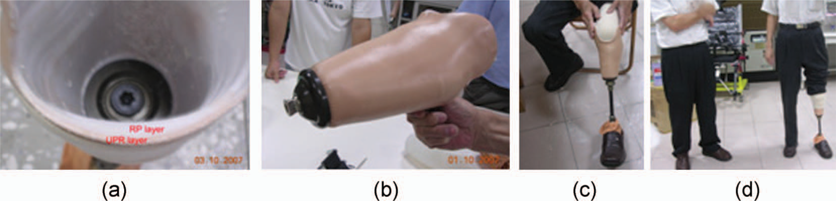
To verify applicability of the proposed resin-reinforced RP socket, the Institutional Research Board in the authors' affiliation approved an experiment testing socket use. As soon as the amputee can safely walk, wearing the resin-reinforced RP socket and a registered physical therapist and prosthetist confirm proper adaptation to the feet and the socket, the experiment then uses the prosthesis to measure interface pressures between socket and stump. This study recruits one male volunteer who is a traffic accident victim with unilateral left side BK amputation. The amputee works in a prosthesis firm, age 59, 1.76 m height and weight 60 kg, and has 31 years of experience in wearing a PTB-supracondylar (PTB-SC) prosthesis without major gait deviation. He is able to walk outdoors without any assistance device and has no cardio vascular or mental illness.
To measure local pressure distribution at the residual limb and socket interface, this experiment employs a Novel Pliance mobile system 15 and socket sensors with 30 × 30 mm2 sensing area. The experiment calibrates the sensors to eliminate variation among them. Figure 6 shows the sensors taped on the appropriate PT/PR areas of the stump for measurement. The measured areas in this study include those main PT areas that bear the weight of the amputee, such as the patella tendon, the medial tibia flare; and the PR areas on which too much pressure may cause pain, such as the tibia end, the tibia crest, the fibula head and the fibular end. The Pliance mobile box connects to a computer and the data can be detected and recorded on the computer. The experiment requested the volunteer subject to walk a 10-meter walkway at a comfortable walking speed. The experiment collected data repeatedly five times for statistical analysis, and Pliance-m Expert 15 extracted and analyzed the measured data.
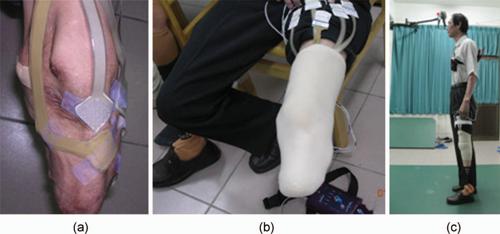
Socket sensors stuck to the stump, and interface pressure measurement.
Results
Following the computer-aided engineering process shown in Figure 1, an FDM machine fabricated two resin-reinforced RP sockets to fit the specific volunteer stump. The first RP socket did not properly fit the volunteer stump shape as the patient felt pain around the lateral tibial flare area. This study again modified the first CAD socket model at the specified area according to prosthetist judgment. This work then manufactured the second resin-reinforced RP socket which gained better socket fit. Except for the volunteer's subjective view, interface pressure comparison between socket and stump is an objective result of using this type of RP socket. This investigation measured interface pressures of three other manually made transtibial prosthetic sockets for the volunteer subject. They include an old socket (a socket used by the volunteer amputee for twenty years), a PPS (polypropylene sheet) socket, and a handcrafted UPR socket. Interface pressures exerted on the resin-reinforced RP socket have a similar pressure distribution compared to other sockets during the stance phase. Figure 7 depicts that the patellar tendon (a major PT area) bears more pressures, while fewer pressures exert on the tibia end and fibula head, also major PR areas. Comparison results demonstrate that the resin-reinforced RP socket reported in this article can apply to the volunteer amputee.
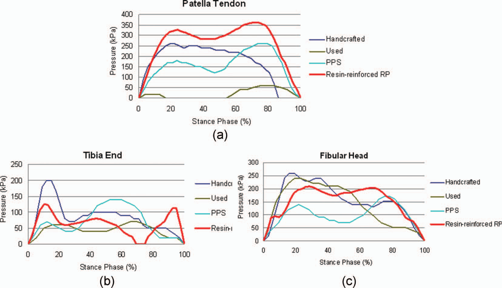
Comparison of the interface pressures among various types of sockets.
Compared to the plaster-based method, the proposed computer-aided process can easily reproduce a replica socket with minor modification, such as the second socket for the specific amputee in this study easily receiving consistent socket fit. Moreover, the proposed computer-aided process requires no plaster cast. The computer-aided process to produce a prosthetic socket should involve a prosthetist and an experienced CAD system user. The procedure that embeds a prosthetic socket design into the CAD system involves amputee participation only at the very beginning when scanning the stump and at the final step of rectifying the socket.
Although this study involves only one participant to date, another subject using a PTB-SC socket for 12 years, who is a unilateral left BK amputee age 26, 1.75 m height and weight 75 kg, has joined this project. The young volunteer is also a research member and is investigating suitability of the resin-reinforced RP socket fabricated by following the proposed procedure. One resin-reinforced RP socket has been manufactured for this second amputee. However, the socket shape did not fit the supracondylar area properly so that the first RP socket easily loosened from the knee, making interface pressures difficult to measure. As soon as the strength of resin-reinforced RP sockets is approved in further study, the second RP socket for the young volunteer will then be evaluated and a larger number of amputee participants may be involved. This study will make more detailed comparisons with the traditional plaster-based process.
Conclusion
This work develops a new type of transtibial prosthetic socket, composed of a polymer layer of polycarbonate made by an FDM RP machine and coated with a layer of unsaturated polyester resin. Measuring interface pressures exerted on the stump verifies applicability of fitting the resin-reinforced RP socket to a transtibial amputee.
This study also establishes a computer-aided engineering process that aids the design and manufacture of a new type of prosthetic socket. This process is free of plaster molds and is also expected to improve the messy production environment of the manual process, which uses considerable amounts of gypsum.
Although the resin-reinforced RP socket this study reports is different from other types of sockets developed by various research groups using either SLS, FDM, or droplet/binder RP machines, its bending strength might need validation by a testing process such as the three-point testing method. An experiment to determine the appropriate parameters (which may include RP material, thickness of the RP layer, forming orientation of the preliminary RP socket, thickness of UPR layer coating) for building resin-reinforced RP prosthetic sockets of proper flexural strength is underway.
Footnotes
Acknowledgements
The authors wish to acknowledge the National Science Council Taiwan for the grant NSC97-2221-E-006-105 in support of this study.