
Abstract
Carbon fiber (CF) is an important structural material due to its favorable mechanical and physical properties. However, poor interfacial bonding with polymer resin severely affects the mechanical performance of carbon fiber reinforced polymer composites (CFRP). In this study, the single-fiber CFRPs were treated using multi-stage cryogenic approaches to optimize the interfacial shear strength (IFSS) between carbon fiber and epoxy resin. The carbon fiber was pretreated by cryogenic treatment with sharp and slow cooling rates, followed by the same treatment of the single-fiber CFRP composed of the pretreated carbon fiber to reach the optimal interfacial modification. The IFSS value was increased by 27.4% when the carbon fiber was pretreated at a slow cooling rate, and its single-fiber CFRP was treated at a sharp cooling rate.
Keywords
Introduction
Carbon fiber reinforced polymer composites (CFRP) have been widely applied in aerospace structures and transportation due to their outstanding properties, such as high specific strength and high specific modulus.1-3 However, the carbon fiber presents poor interfacial bonding with the matrix because of the smooth, non-reactive groups and low chemical activity of the fiber surface. The fiber and matrix bonding strength is critical to load transfer from the matrix to the reinforcement, and thus essential to its mechanical properties.4-7 Some researchers proposed use of chemical and physical methods for carbon fiber surface modification, such as electrolytic oxidation,8,9 acidic oxidation,10,11 plasma treatment,12,13 and other methods.6,14 However, these methods have some shortcomings, such as degradation of the intrinsic properties of the fiber and environmental damage.
Cryogenic treatment methods have been used to modify the comprehensive properties of high-performance fibers and their composites.15-18 Cryogenic treatment is basically carried out using a cryogen (e.g., liquid nitrogen or helium) in a cryostat, followed by holding it for a programmed time and then progressively leading it back to room temperature (RT).
Compared to isotropic polymers, carbon fiber is anisotropic. At the same time, the coefficient of thermal expansion between the carbon fiber and the matrix is different. The shrinkage of the matrix is greater than that of the carbon fiber during cryogenic treatment, producing axial pressure on the carbon fiber, which helps to achieve better mechanical interlock between the fiber and the matrix. 15 Melcher and Johnson 9 observed that the matrix produces plastic flow during cryogenic treatment, which allows cryogenic welding to extend the fully elastic behavior of the composites. In addition, reinforcement particles added to the composites were more evenly distributed after cryogenic treatment, which can enhance the interface and mechanical properties of the composites. 20 Studies have suggested that the amorphous carbon on the surface of the carbon fiber will become rough during cryogenic treatment, making the grooves on the fiber surface wider and deeper. These serve as mechanical interlocking sites, which can enhance frictional interaction and improve the interfacial bonding of the single-fiber composites.15,21,22 However, the effect of low temperature on the interface properties of CFRPs was not systematically studied.
The interfacial shear strength (IFSS) was determined to characterize the stress transfer from the matrix to the fiber. Among all the IFSS methods tested, including pull-out, 23 micro bonding,4,22 fragmentation,8,11,20,24-30 and the micro-indentation test, 31 the fragmentation test is effective to study complex failure phenomena by microscopy with good reproducibility and to obtain information both on the fragment length and the interface failure mode. 24 Moreover, it was found to be the most appropriate method for CFRPs since carbon fiber is highly brittle with its small diameter. 25
Previous work studied the effects of cryogenic treatment on the tensile and interface properties of carbon and aramid fibers, and carbon nanotubes.13-18 However, these prior studies mainly focused on changes in tensile and surface properties based on morphological characteristics. Also, the cryogenic treatment methods used previously were single-stage treatments, with few studies on the interfacial properties of single-fiber composites prepared using multi-stage cryotreated carbon fibers. Hence, in the present study, multi-stage cryogenic approaches and a more detailed morphological analysis were used to optimize the interfacial properties of single-fiber CFRPs.
The morphological characteristics and Weibull distribution of different cryogenic treatments were analyzed to compare the effects of various cryogenic treatments on the surface properties of carbon fibers. The fragmentation test and polarized light microscopy were used to observe the interfacial adhesion behavior in single-fiber CFRPs. IFSS values were calculated using the model of Henstenburg and Phoenix, 29 based on the Poisson/Weibull distribution of the tensile behavior of carbon fibers and Monte Carlo simulation. Finally, the composite cross-sections were observed by scanning electron microscopy (SEM) to analyze the effect of cryogenic treatment on the interfacial properties of the composite.
Experimental
Material Preparation and Cryo-Treatment
This experiment used T300-12000 carbon fiber produced by Toray Industries, Japan. Its tensile strength was 2.86 GPa, Young's modulus was 193 GPa, and the elongation was 1.49%. Single filament composite (SFC) specimens were prepared using the carbon fibers and the epoxy blends (Epolam 2008 epoxy resin and Epolam 2008-F curing agent from Axson Technologies Shanghai Co. Ltd., China) mixed in a ratio of 5:1. The cryogenic treatment system is shown in Fig. 1.
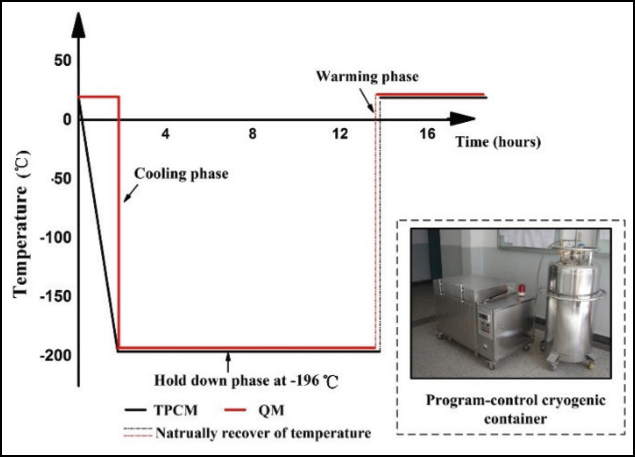
Schematic of cryogenic treatment processes under different cooling rates.
The dog-bone shaped specimens were cured at 60 °C for 6 h and then cooled slowly to RT. Before cryogenic treatment, the fibers were cleaned by immersion in acetone solvent for 30 min, and then washed with distilled water. Cryogenic treatment was carried out using a temperature-program controlled cryogenic chamber (SXL-30, Chemicophysics Research Institute of the Chinese Academy of Sciences (CAS), China). The cryogenic treatment was divided into a temperature program-controlled method (TPCM) and a quench method (QM). The carbon fibers and SFC were treated in four cryo-treatment groups as shown in Table I. In the TPCM, the samples were cooled from RT down to -196 °C at a rate of 2 °C/min, and then maintained at that temperature for 12 h. In the QM process, the specimens were directly placed into a liquid nitrogen (-196 °C) environment, suddenly exposing the samples to a cryogenic temperature, and then maintained at -196 °C for 12 h.
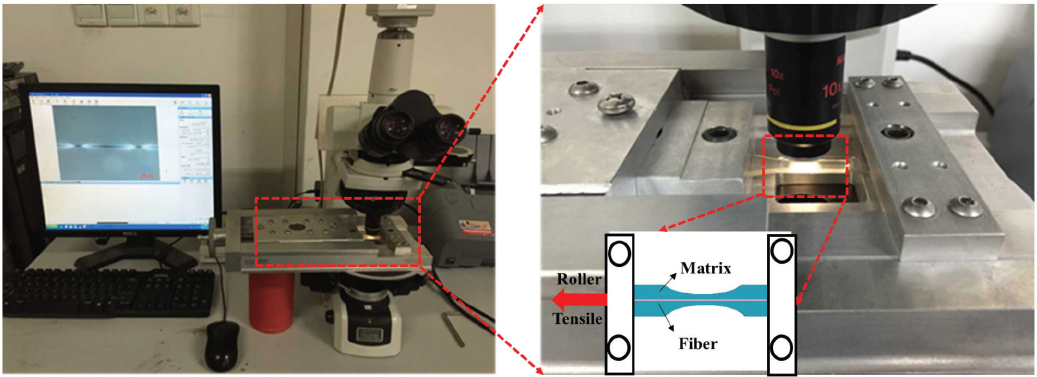
Cryogenic Treatment Samples
F in sample name indicates Fiber, and M in sample name indicates Matrix.
Single-Fiber Tensile Test
Tensile properties of the single fiber were measured using a single-fiber tensile testing machine (XS (08) XG, Shanghai Xusai Instrument Co., China) at a crosshead speed of 20 mm/min and a gauge length of 20 mm at 20 °C and 65% relative humidity (RH). The diameter of the fiber was measured by a polarized light microscope (Eclipse LV100 POL, Nikon) with a digital image capturing system. At least 50 specimens were tested by the same method as reported.
Fragmentation Test and Characterization
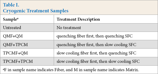
The fragmentation method was used to measure the inter-facial properties of single-fiber CFRPs before and after cryo-treatment. A micro tensile test device was used to fix and apply tension to the single-fiber CFRPs. The micro tensile test device was placed on the objective table of the polarized light microscope, then the rocker drafting of the micro tensile machine was slowly rotated to apply tension to the sample at a rate of 2 rpm (a circle 0.64 mm), and then stopped so that no new fracture occurred. The fractures of single fibers resulting from the tensile process were observed and recorded by polarized light microscopy. The photograph of the final broken fiber was recorded by a professional camera component (Fig. 2). The fracture surface morphology of the final broken single fiber composite sample was observed using a scanning electron microscope (SEM, Model JSM-5600LV, JEOL, Japan) at a voltage of 15 k V.
Fragmentation test instrument.
Results and Discussion
Weibull Distribution of the Tensile Behavior of Carbon Fibers
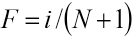
Before calculating the IFSS values between the carbon fiber and the epoxy resin, two important parameters, the shape parameter ρ and scale parameter σ0, were confirmed by Weibull statistical analysis of the single-fiber tensile test (results available from the author upon request). The strength of the fiber obeys the two-parameter Weibull distribution 32 expressed by the empirical Eq. 1.
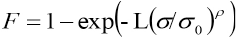
σ is the tensile strength, F is the failure probability of an individual fiber at an applied stress of σ, L is the length ratio about the reference length, σ 0 is the scale parameter and ρ is the shape or flaw dispersion parameter.
The experimental data can be ranked in ascending order of strength values and the cumulative probability can be assigned as in Eq. 2.
i is the rank of the tested fiber in the ranked strength tabulation and N is the total number of tested fibers.
Therefore, Eqs. 1 and 2 can be rearranged to give Eq. 3.
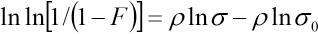
A linear regression analysis can be applied to a plot of ln[l/(l - F)] vs. ln σ, as shown in Fig. 3a. σ 0 and ρ are obtained by the slope and intercept of the corresponding fitting line. Values of Weibull parameters obtained from the linear regression analysis of the fibers in the different process are given in Table II. After cryogenic treatment, the shape parameter declined a little, reflecting an increase in the discreteness of the carbon fiber strength. The scale parameter also displayed a decreasing trend in accordance with the results of Zhang et al. 15
Weibull Parameters of Cryo-Treated Carbon Fibers
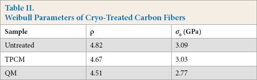
(a) The Weibull plots. SEM images of (b) untreated carbon fiber, and (c) carbon fiber treated by TPCM process, and (d) carbon fiber treated by QM process.
The SEM photograph of the untreated carbon fiber is shown in Fig. 3b. It shows the characteristics of a typical polyacrylonitrile (PAN)-based carbon fiber, with some grooves distributed longitudinally. After TPCM treatment (Fig. 3c), the grooves on the fiber surface were slightly wider and deeper, and the surface was rough; while after QM (Fig. 3d) treatment, the fiber surface had no significant changes. The main reason for the TPCM result was that the low cooling rate allows the movement of the graphene layer to adapt to the shrinkage caused by the temperature drop, forming a tighter core structure, while expanding and merging micropores along the fiber axis in the skin, making the grooves on the fiber surface wider and deeper. However, after the QM process, because the graphite layer was suddenly frozen, there was no time to adapt to the instantaneous cold shock. Therefore, the surface roughness did not change significantly.
Interfacial Shear Stress
The Henstenburg and Phoenix model 29 to evaluate the IFSS value of the fragmentation sample was proposed by considering that the flaws along a fiber obeyed the Poisson/Weibull distribution and Monte Carlo simulation of the fragmentation process. The formula of the IFSS (τ) is shown as Eq. 4.
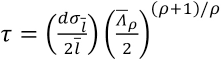
Using the Weibull weakest link scaling to account for size effect,
l0 is the gauge length from single fiber strength tests and σ 0 is the Weibull scale parameter for single fiber strength measured at gauge length l0.
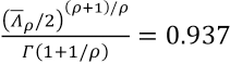
Birefringence pattern (Fig. 4a) is a schematic of the fragmentation test. Due to the difference in modulus between the resin and the fiber, when the sample was subjected to a load, the resin first deforms, transferring the stress to the fiber through the interface. When the strain of the sample was increased to reach the elongation at break of the carbon fiber, the fiber would fracture continuously. The shorter the length of the fiber, the larger the IFSS between the fiber and the resin. Polarizing light microscopy was used for the fragmentation test. Stress birefringence occurs when the local density of the epoxy resin matrix changes during the application of tension, leading to a change in the refractive index. Studies have shown that three damage modes can be analyzed from the birefringence patterns of fiber fracture points: frictional debonding, interfacial cracks, and matrix cracking.27,29-31,33 Fig. 4b shows the birefringent pattern of the untreated composites. Figs. 4c–f shows the birefringence patterns of the composites prepared by four different cryogenic treatment methods. All samples did not show the matrix cracking, and these five samples showed the damage characteristics of interface cracks. The stress birefringence patterns of TPCMF+QM and QMF+QM were connected end-to-end, and the stress extension range was larger. Therefore, it can be preliminarily judged that the IFSS of these two samples was significantly higher than that of other samples.
(a) Schematic of fragmentation test. Birefringence patterns of (b) untreated, (c) QMF-QM, (d) QMF-TPCM, (e)TPCMF-QM, and (f) TPCMF-TPCM.
Average Fracture Length
The average fracture length was measured from the polarized light photos of samples during the fragmentation process. Image-Pro Plus, a professional image processing software, was applied to record and measure the average fracture length of carbon fiber fragments in the epoxy matrix. The results are shown in Fig. 5. For the untreated single-carbon fiber composite, the fracture length was distributed throughout a wider length range of 370 to 610 μm and the average fracture length was the longest (489.3 μm) compared with cryo-treated samples. For the cryo-treated single-carbon fiber composite, the average fracture lengths were shorter and the fracture length distributions were narrower. Among the cryo-treated single-carbon fiber composites, the average fracture length of QMF+TPCM samples was the longest (460.82 μm), which indicated this treatment had an unsatisfactory effect. However, most of the fracture length of the TPCMF+QM samples (>80%) were distributed in the narrowest scale range of 340 to 500 μm, and had the shortest fracture length of 396.49 μm, which indicated the greatest strength of adhesion between carbon fiber and resin.
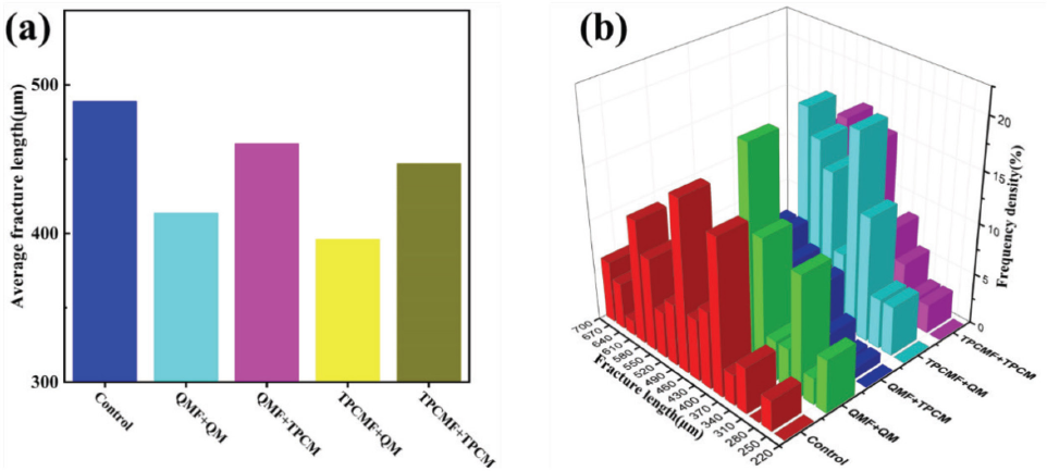
(a) Average fracture length of carbon fiber in single-fiber composite and (b) fracture length distribution of carbon fiber in single-fiber composite.
IFSS of Cryo-Treated Single-Fiber Composite
Using Eqs. 1–6, the IFSS results were calculated and shown in Fig. 6. All of the IFSS values of cryo-treated composites increased. For TPCMF+QM samples, its IFSS increased by 27.4%, from 41 MPa to 52.5 MPa, when compared to the single-stage cryogenic treated samples (data available from the author upon request). The IFSS value of the other three composites also increased by 15.3% (QMF+QM), 3.4% (QMF+TPCM), and 11.9% (TPCMF+TPCM).
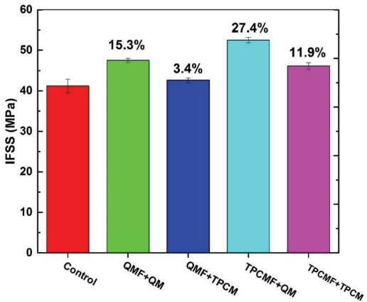
IFSS of cryo-treated single-fiber composite.
Previous studies pointed out that carbon fiber had a skin-core structure. 15 The skin is mostly composed of relatively well-organized graphite layers, while the core has a much less organized turbostratic structure. The low cooling rate allows the movement of the graphene layer to adapt to the shrinkage caused by the temperature drop, forming a tighter core structure. The curling of the surface layer prevents it from being reinforced like a turbocharged core, so the grooves on the fiber surface become wide and deep. However, after the QM process, because the graphite layer was suddenly frozen and there was no time to adapt to the instantaneous cold shock, the surface roughness did not change significantly.
When performing QM processing on a single-fiber CFRPs, the epoxy resin shrank more severely than that treated by TPCM due to the sharper decrease of the temperature. Therefore, more hoop stress was generated on the carbon fiber of the single-fiber CFRPs. Taking account of the rougher surface of the TPCM treated fiber, the TPCM+QM sample exhibited greater fiber/matrix interfacial shear strength than other treated fibers.
SEM Analysis of Fragments Section
The fracture cross-sectional images of single-fiber CFRPs are shown in Figs. 7a–j. All the failures of single-fiber CFRPs in this study were adhesive failures. However, the interface strength between the fiber and the resin matrix can affect the length of fiber extraction when the single-fiber CFRPs failed. It can be seen from Figs. 7a and f that, for the untreated samples, the fiber had the longest drawn-out length, and the gap between the carbon fiber and the resin was obvious, which indicated that the interface bonding performance was poor. After cryogenic treatment, the length of the fiber pulled out decreased. Among them, Figs. 7d and i showed that the length of the protruding fiber of the TPCMF+QM sample was shorter than for untreated samples, and there was almost no gap between the fiber and the resin. This indicated that the interfacial performance of the TPCMF+QM sample was better than the untreated samples, and that the IFSS value was the highest as described above. For the QMF+QM (Figs. 7b and g) and TPCMF+TPCM (Figs. 7e and j) samples, the drawn-out length of the fiber was similar, and the gap between the carbon fiber and the epoxy matrix compared to the untreated sample was also narrower. This demonstrated that the processing methods of QMF+QM and TPCMF+TPCM helped to enhance the interfacial bonding behavior. The QMF+TPCM sample (Figs. 7c and h) had a longer fiber pull-out length than the treated sample, and there was an obvious gap between the fiber and the resin, which proved that the QMF+TPCM treatment had no obvious effect on the interfacial bonding performance.
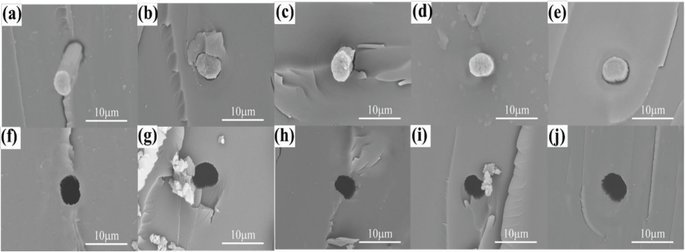
SEM fragment cross-section of different samples; (a,f) untreated, (b,g) QMF-QM, (c,h) QMF+TPCM, (d,i) TPCMF+QM, and (e,j) TPCMF+TPCM.
Conclusions
In this study, the single carbon fiber reinforced polymer composites (CFRPs) were treated by various multi-stage cryogenic approaches, and the fracture models of the composites were explored by analyzing the birefringence and fracture morphology of the composites. The results showed that cryogenic treatment can increase the interfacial property, but slightly influenced the tensile property, of carbon fiber. The single-fiber CFRPs treated by TPCMF+QM cryo-treatment showed the shortest average fracture length and the highest increment of IFSS improvement (27.4%) according to the Henstenburg and Phoenix model. This study demonstrated that multi-stage cryogenic treatments can effectively improve the interfacial property of the carbon fiber composites.
Footnotes
Acknowledgements
This project was funded by the State Key Laboratory for Modification of Chemical Fibers and Polymer Materials, Donghua University, Fundamental Research Funds for the Central Universities (Grant No. 2232019G-02), DHU Distinguished Young Professor Program, and Shanghai Natural Science Foundation (Grant No. 17ZR1400800).