
Abstract
Different approaches are used for the integration of ceramic components in solid oxide fuel cells stacks, where dissimilar materials (ceramics and metals) have to be joined and coupled for a reliable long term operation. This work focuses on the mechanical characterisation of a glass ceramic sealant used for the joining of Crofer22APU metallic interconnect samples as well as the interaction with a preoxidised Crofer22APU. Crofer22APU–glass ceramic sealant joined samples are tested by two different mechanical tests. Hourglass samples with different geometries were tested using an in-house developed torsion test machine at room temperature. In addition, their mechanical strength was also evaluated according to the ISO 13124 standard. The comparison of the two different testing methods, with particular focus on the shear strength of the joined samples, are reviewed and discussed.
Introduction
Solid oxide fuel cells (SOFCs) are electrochemical devices that convert chemical energy into electrical energy by red–ox reactions between a fuel and an oxidant. In order to obtain a satisfactory output power, it is necessary to build an SOFC stack. 1 Some of the stack elements must be joined by a sealant. A reliable sealant for SOFCs should have an excellent gas tightness, a high resistance to relevant conditions and a coefficient of thermal expansion (CTE) as closer as possible to that of materials to which they are in contact with. 2 Glass ceramic sealants are considered as among the most promising materials for this application.3,4 This is mainly due to the possibility of tailoring their thermal and thermomechanical proprieties by changing their composition and, in general, glass ceramics have superior mechanical proprieties compared to their parent glasses. Glasses can be deposited on different substrates in the form of slurries or pastes; the subsequent heat treatment necessary for the joining processing can determine a devitrification process that consequently can lead to the formation of crystalline phases.5–10 The thermomechanical compatibility of the glass ceramic sealant with the other components can critically influence the reliability and the robustness of SOFC stacks, in particular, the mechanical properties of the sealant–interconnect joints. The mechanical properties of a joined sample depend of course not only from the two materials to be joined but also from the mechanical strength of the interface between the glass ceramic sealant and the metallic interconnect.
The stability at the sealant/interconnect interface depends on the composition of the sealant, on the interconnect surface (uncoated, coated or preoxidised) as well as the stack operating temperature. It is required that reactions between the sealant and the coating or the metallic interconnect are limited during SOFC operating conditions; otherwise, detachments and spallation at the interfaces can occur, thus determining leakage and consequent failure with the SOFC performance degradation.
Few studies have recently investigated the mechanical properties of SOFC metallic interconnect joined by glass ceramic sealants, in particular by evaluating their tensile strength.11–14 Tensile tests were all carried out at room temperature with different specimen configurations. Gross et al. published an improved tensile strength test set-up showing a very good reproducibility. 15 Malzbender and Zhao reported the results of flexural strength of glass ceramic sealants using a head to head joined specimens configuration (according to the ASTM C1161 standard). 16 Lin et al. used the ISO 13124 test method to evaluate the tensile and ‘shear bond strength’ of yttria stabilised zirconia to stainless steel joints using Ag–Cu–Ti interlayers: a cross-bonded joined sample has been loaded in compression until the beginning of debonding. 17 The load at fracture and the bonded area were used to assess both the tensile and the ‘shear’ bond strengths.
In the SOFC stack working condition, sealants can be subjected to a combination of tensile and shear loads that could lead to failure. In order to model the mechanical behaviour of a stack, designers need the pure tensile and the pure shear strength of the joined components: if standards are available to measure the pure tensile strength (ASTM C633-01), a reliable shear strength test for joined components is still missing.
One of the very few tests able to measure the pure shear strength of joined materials is the asymmetrical four-point bending (ASTM C1469-10), recommended for joined ceramics. Together with several issues already reported about the feasibility of this test and its unsuitability when the joint strength approaches that of the joined material,18–21 its very applicability in the case of metal to ceramic or metals to metal joints is not straightforward. Other tests proposed for metal to metal joints are based on lap joined configurations and give an apparent shear strength, which cannot be used to provide pure shear strength.
Ferraris et al. 19 proposed some modifications of the torsion test (ASTM F734-95 and F1362-97 for plastics)22,23 as an alternative test to measure the pure shear strength of the joints.
Comparisons of different joining materials require one reliable test method, possibly with optimised specimen geometry in order to obtain pure shear strength and limit the undesirable effect of mixed stresses in the joined area during mechanical tests.
The work that is presented here discusses the comparison of two different tests; one is based on torsion, the second one is ISO 13124, both used to measure the shear strength of glass ceramic joined steel for SOFC.
Experimental
The sealant (labelled as KMBY) was produced by melting the appropriate oxides and carbonate raw materials, with the following percentages (wt-%), to form a glass: SiO2, 54.39; Al2O3, 11.26; CaO, 9.02; Na2O, 13.78; MgO, 8.37; K2O, 1.67; and B2O3(Y2O3, 0.61. The raw materials were distributed by Sigma-Aldrich (grade of purity higher than 99%). The mixed powders were heated at 1500°C for 1 h in a Pt–Rh crucible. The melt was cast on a brass plate, and the transparent glass was ground for thermal characterisation.
The characteristic temperatures of the glass and other details can be found in Smeacetto et al. 24 The metallic interconnect used for this study was Crofer22APU (Thyssen Krupp, Germany), a ferritic stainless steel (22 wt-% chromium) exhibiting a CTE of 11.5 × 10− 6 K− 1.
For the torsion tests, Crofer22APU was machined into miniaturised hourglass shaped samples (referred to as THG-5) with a full joined surface of 5 mm diameter (Fig. 1, right side); some THG-5 have been drilled through the whole thickness with a 3 mm hole (referred to as TDHG), in order to reduce the joined surface to an annular shape, as reported in Fig. 1 (left side); a detailed schematic of geometry used for the torsion test is also shown.
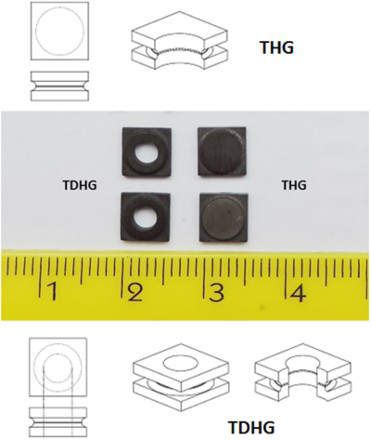
Hourglass Crofer22APU shaped samples; TDHG (left) with ring shaped joined area (5 mm outer diameter, 3 mm inner diameter) and THG-5 (right) 5 mm diameter fully joined area: detailed schematic of geometry used for torsion test
For ISO 13124 tests, Crofer22APU was machined into 4 × 2.5 × 25 mm bars to produce cross-bonded joints of 4 × 4 mm.
Before the joining process (for both the torsion and ISO 13124 tests), Crofer22APU samples were preoxidised at 950°C for 2 h in air.
The as cast glass sealant was powdered to an average particle size lower than 38 μm and dispersed in ethanol to obtain a slurry; the slurry was deposited on each side of the two steel parts to be joined in a controlled amount in order to obtain a joining thickness of 250 μm, similar to the existing one in a real SOFC stack.
All samples for the torsion tests were then positioned in a graphite sample holder, as shown in Fig. 2a, with the purpose of holding the samples in position during the joining heat treatment.
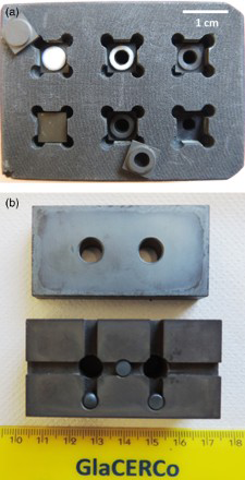
a graphite sample holder with glass slurry deposited on two half hourglass samples, THG (upper part, left) and TDHG (upper part, centre) and ready to join hourglass samples (lower part) and b stainless steel sample holder for joining of ISO 13124 cross-bonded samples
For the ISO 13124, the cross-bonded samples were positioned in a stainless steel sample holder, as shown in Fig. 2b, with the same purpose as above.
The joining thermal treatment for processing both hourglass and cross-bonded samples was carried out by heating from room temperature to 850°C at a heating rate of 5°C min− 1 and a dwelling time of 30 min. The cooling rate was 5°C min− 1.
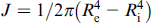
For torsion tests, the maximum shear strength is calculated by
19

For TDHG samples with an annular cross-section of exterior radius Re and interior radius Ri
All ISO 13124 standard tests were conducted using a crosshead speed of 0.5 mm min− 1, and cross-joined samples were loaded according to the schematic reported in Fig. 3, showing the cross-bonded sample with the glass ceramic joined area and fixture for measuring the shear bond strength. Cross-sections of joined samples before and after the mechanical tests were characterised by scanning electron microscopy (SEM) (JEOL 5700). Energy dispersive X-ray spectroscopy microanalysis was also carried out to inspect for any chemical interactions between the preoxidised Crofer22APU and the glass ceramic sealant.
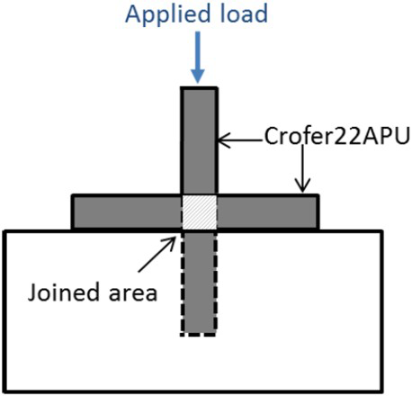
Schematic of cross-bonded sample and fixture for measuring shear bond strength according to ISO 13124 standard
Results and discussion
The glass composition labelled as KMBY from oxides used as starting products was selected in order to obtain adequate characteristic temperatures and CTE compatible with the Crofer22APU steel. The composition has been specifically designed by considering that alkali oxides adjust glass viscosity, decrease characteristic temperatures and increase the wettability on the metallic interconnect. This particular composition was also chosen for its good sintering behaviour at a joining temperature of 850°C, as reported in Smeacetto et al. 24
During the joining process, the glass partially crystallises to give a glass ceramic, and the increased viscosity can induce residual porosity in the joint: the best found compromise between residual porosity and degree of crystallisation in the joint was obtained using the KMBY glass powder with average particle size lower than 38 μm and heat treatment at the temperature of 850°C for 30 min. 24
The Crofer22APU steel contains small amounts of Mn and, after heat treatment in air at 900°C, coated by a double layer oxide scale (preoxidation layer), which consists of a protective Cr2O3 subscale and an outer (Mn,Cr)3O4 spinel layer. 25 The formation of the oxide scale ensures a very good compatibility between the metallic interconnect and the glass based oxide system; a transitional zone in which the metallic bond is gradually substituted by the ionic–covalent bond of the glass leads to a good adhesion between the metal and sealant. Furthermore, the oxide scale can be also effective in preventing Cr diffusion from the metallic interconnect into the glass ceramic sealant, thus avoiding possible formation of new phases with different thermomechanical properties and possible detachment at the interface. Figure 4 shows an SEM cross-section of the preoxidised Crofer22APU/KMBY glass ceramic sealant interface after the joining process at 850°C, 30 min. As it can be seen, the thickness of the preoxidation layer is ∼1 μm, and it appears to be homogeneous along all the interface with the Crofer22APU substrate. The interface between the glass ceramic sealant and the oxide scale on Crofer22APU is found to be free of cracks, thanks to a good thermal expansion coefficient match of the glass ceramic sealant (calculated as 10.9 × 10− 6 K− 1) with that of the Crofer22APU and other defects such as pores, thus confirming a very good sintering of the glass. 24
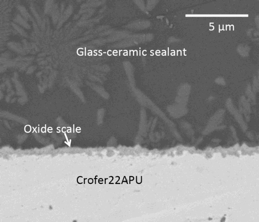
Scanning electron microscopy cross-section of preoxidised Crofer22APU/KMBY glass ceramic sealant interface after joining process at 850°C after 30 min
KMBY glass ceramic has been obtained by sintering particles lower than 38 μm for 30 min at 850°C; X-ray diffraction measurement published in Smeacetto et al. 25 revealed the presence of diopside (Ca0.89Mg1.11Si2O6) as the main crystalline phase embedded in the dark glassy phase.
Figure 5 shows the typical shear stress–displacement curve obtained after torsion tests of THG hourglass and TDHG joined samples. The elastic behaviour up to brittle fracture is revealed, as expected by a glass ceramic joining material. In the case of brittle joining material, structure mechanics demonstrates that the torsional shear strength of a fully joined sample (THG-5) must be equivalent to that of a ring shaped one (TDHG) of the same diameter.19,26
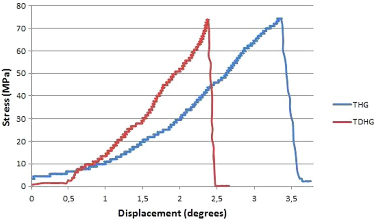
Typical shear stress–displacement curve obtained for torsion test of THG and TDHG hourglass joined samples
This torsion method was originally tested with steel hourglasses joined by an epoxy resin, carbon/carbon composites and bulk ceramics tubes, cylinders and hourglasses bonded with an epoxy resin and, finally, on silicon carbide hourglasses joined by a glass ceramic; the results showed that it was possible to measure pure shear strength values when the fracture propagates in the joined area and when the measured strength is size independent.18,19
Contrary to what was reported for glass ceramic joined ceramics tested with this torsion test, 19 all the glass ceramic joined steel samples exhibited the fracture only in the joined area for both TDHG and THG-5 configurations, at a shear strength of 71 ± 5 MPa on 12 samples (six TDHG and six THG-5 joined samples). This is a demonstration that this test is size independent for this couple of joined materials. Since the joining material is purely brittle, there is no difference in what was measured by torsion on a fully joined sample (THG-5; bonded area, 19.6 mm2) and on a ring shaped one (TDHG; bonded area, 12.6 mm2). As a consequence, the measured value can be taken as the pure shear strength of this glass ceramic joined steel.
Figures 6a and b shows the fracture surfaces of THG-5 and TDHG respectively, after torsion tests.
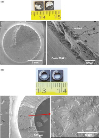
Fracture surfaces of a THG-5 and b TDHG joined samples after torsion test
The cohesive fracture surface after torsion tests (Fig. 6) confirmed the good adhesion and interface strength between the glass ceramic sealant and the Crofer22APU, as predicted by the high wettability of this glass ceramic sealant on the Crofer22APU substrate (Fig. 4); in particular, the inset of Fig. 6a is reported to show the very good adhesion and wettability of the glass ceramic onto the preoxidised Crofer22APU. The magnification of Fig. 6b shows crystals on the fracture surface that, on the basis of the X-ray diffraction measurements reported in Ref. 25, can be ascribed to the diopside phase.
Furthermore, also with the ISO 13124 standard test, all the tested samples fractured only in the joined area, as it can be observed in Fig. 7. However, with this cross-bonded configuration, the bonded area (16 mm2) is subjected to combined shear, tensile and bending stresses, as typically occurring with lap tests.27,28 The apparent shear strength, measured on six samples by ISO 13124, was 42 ± 6 MPa; as expected, this value is much lower than 71 MPa obtained by the torsion test, where a pure shear strength can be obtained.
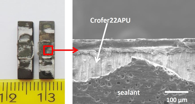
Fracture surfaces of cross-bonded joined samples after ISO 13124 test
On this respect, it must be underlined that ASTM D1002-10 (Ref. 29) caveat on all the lap joint strength tests: ‘the apparent shear strength measured with a lap specimen is not suitable for determining design allowable stresses for designing structural joints that differs in any manner from the joints tested without thorough analysis and understanding of the joint and adhesive behaviors’.
The proposed torsion test configuration could be considered a promising method to measure the pure shear strength of glass ceramic joined steel samples to be used in SOFCs. Further investigation and modelling activity are ongoing.
Conclusions
In this work, we discussed the mechanical characterisation of a glass ceramic sealant used for the joining of Crofer22APU metallic interconnects. The glass ceramic sealant demonstrated a very good sintering behaviour and an excellent thermomechanical compatibility and adhesion with the preoxidised Crofer22APU.
The comparison of two different test methods (torsion test and ISO 13124) have been presented with the aim of measuring the pure shear strength of these glass ceramic joined steel samples. A pure shear strength of 71 ± 5 MPa was obtained on 12 samples by the torsional test on six fully joined (THG-5) and six ring shaped (TDHG) joined samples, while an apparent shear strength of 42 ± 6 MPa was measured on six samples by the ISO 13124 standard, where the bonded area is subjected to combined stresses.
Footnotes
Acknowledgements
The research leading to these results has received funding from the European Union's Seventh Framework Programme managed by REA-Research Executive Agency ![]() , and it participates in a Marie Curie Action (GlaCERCo GA 264526). ADMACOM ‘Advanced manufacturing routes for metal/composite components for aerospace’ and Italy–Japan bilateral (High National Relevance) projects are also acknowledged.
, and it participates in a Marie Curie Action (GlaCERCo GA 264526). ADMACOM ‘Advanced manufacturing routes for metal/composite components for aerospace’ and Italy–Japan bilateral (High National Relevance) projects are also acknowledged.