
Abstract
The microstructure sensitive multistage fatigue model captured the fatigue life of a powder metal FC-0205 steel alloy. Uniaxial strain controlled fatigue data and microstructure information from sets of high and low porosity specimens calibrated the model. Strain–life behaviour depicted that above the plastic strain limit of 0·002 mm mm−1 in the low cycle fatigue regime, where ubiquitous plasticity occurred, the different porosity levels gave distinct, visibly different results. However, specimens tested below the plastic limit in the high cycle fatigue regime, where failure was dominated by local cyclic microplasticity, showed unclear fatigue lives at different porosity levels. Fractography using scanning electron microscopy showed no clear presence of striations; however, asserted striations in powder metal specimens were similar to geometrical features observed on fracture surfaces of monotonically loaded specimens. The experimental and microstructure data calibrated a fatigue model that allowed for satisfactory prediction of the varying porosity specimen strain–life curves.
Introduction
Computational and mathematical based modelling of the thermomechanical behaviour for powder metallurgy (PM) component design and performance predictions are recognised as significant contributions to improving efficiency, quality and cost of generating new business opportunities for the automotive industry. Powder metallurgy techniques are being incorporated to manufacture various complex shaped engineering components, which prove difficult to cast or shape by alternative material processing. A motivating factor driving the development of a mathematically based model is the ability to accurately predict the variation in property performance caused by inhomogeneous density distributions. Research addressing mathematical modelling will provide several benefits, including near net shape components, complex geometries, high strength, and minimal or eliminated finishing operations. 1
Influence of porosity on fatigue properties
Several characteristics of porosity, including pore size, pore shape, pore spacing and percent porosity, have been shown to influence fatigue behaviour in Fe–Cu–C PM alloys.2,3 This influence of porosity on the number of cycles to failure has also been observed in traditionally cast aluminium alloys.4–6 In fact, by decreasing porosity and increasing the number of rounded pores, the plastic deformation was observed to be more homogenous, and ultimately, crack initiation was delayed. Furthermore, work by Chawla and Deng 7 on Fe–Mo–Ni steel showed that pores and pore clusters near the specimen surface typically initiated fatigue cracks. In their work, the pore size and pore clusters acted as stress concentrations for the initiation of fatigue cracks. Regarding crack growth, Sudhakar 8 found that crack propagation during cyclic loading was primarily due to crack linking and/or joining of isolated pores. Similar work by Chawla et al. 9 showed that the propagation of fatigue cracks was dependent on mean pore spacing and that a longer distance for cracks to travel between pores resulted in a higher fatigue life.
Additionally, Lindstedt et al. 10 conducted research on the fatigue of PM materials by testing austenitic stainless steel. The researchers reported that the nucleation of fatigue cracks predominately occurred at or near the surface, where fatigue crack nucleation represented ∼10% of the total fatigue life. Surface crack linking was identified in the higher porosity steel, and the tendency of linking was not found in the low porosity steel. Test results on high strength low alloy PM steel FL-4405 11 showed that lower porosities produced an increase in fatigue resistance over higher porosities, and concluded that pore size and percent porosity had a greater influence on tensile stress–strain, fracture toughness and fatigue resistance than did an increase in pore roundness.
Current PM fatigue modelling
In general, the development of fatigue models for PM materials has resulted in several modelling techniques for various PM materials including statistical methods,12–14 neural network approach, 15 linear elastic fracture mechanics (LEFM), 16 probabilistic continuum damage approach 17 and plasticity based initiation modelling. 7 These methods are similar to fatigue models employed on traditional metal processes.
The neural network approach, undertaken by Iacoviello et al., 15 includes an artificial neural network to examine the stress ratio effects on fatigue propagation. The artificial neural network model that was developed examined R values from 0·1 to 0·9 and correlated fatigue crack growth rate da/dN, stress intensity factor amplitude ΔK and stress ratio R. The restrictions on the model are that the fatigue crack propagation mechanisms cannot change, and to completely develop the model, a large quantity of fatigue tests, which can prove to be expensive, are needed to correlate crack propagation to different stress ratios for training and validation of the model.
The LEFM framework for predicting fatigue limit by Torres et al. 16 uses an approach based on a fatigue crack growth threshold. Here, it is assumed that the fatigue failure in PM high speed steels was caused by crack propagation beginning at intrinsic processing defects (inclusions, carbides and pores). The model was validated by experimentally determined fatigue limit values with an assumption that critical flaws consisted of similar size and geometry for monotonic or cyclic loading conditions.
A probabilistic model developed by Yan et al. 17 for the low cycle fatigue (LCF) regime of a PM material incorporates a Lemaitre–Chaboche damage model. The damage model, which is capable of capturing internal inclusions, was added to Bussac's probabilistic model that considers surface inclusions. The model assumes that all the inclusions are spherical in shape and uniformly distributed throughout the component. Further assumptions are that the damage variable of a material element is equal to the damage of a specimen, the initial damage is dependent only on the size and location of an inclusion, and the LCF life of a component depends on the initial maximum damage. Test data for specimens with internal inclusions were still required for the model to be validated.
Lastly, Chawla and Deng 7 examined sintered density comparisons with fatigue behaviour, Young's modulus and monotonic stress–strain behaviour for sintered Fe–0·85Mo–Ni steel. Analytical modelling using the Ramakrishnan and Arunachalam approach was used to show the experimentally observed decrease in Young's modulus with increasing porosity. To simulate the cyclic behaviour, a combined non-linear isotropic/kinematic hardening material model was employed. Modelling was performed using two-dimensional microstructures obtained from optical micrographs as a basis for the finite element simulations. Extrapolation of the constitutive behaviour of the steel matrix from tensile tests was performed, allowing that the constitutive behaviour was assumed constant for all the porosity levels investigated. A concern is noted by Chawla and Deng that, in two-dimensional modelling, the pores are treated as holes, where in actuality they are surrounded by the material matrix. The results of the modelling showed that, at low densities, the pores were larger, more irregular and highly clustered, causing significant strain localisation resulting in premature failure. When the density was increased so that porosity was lower, spherical pores were observed to be distributed more homogenously, relating to a larger fraction of the material experiencing distribution of the plastic strain. Cyclically, the modelling showed that plastic deformation developed gradually at the corners of pores and at highly clustered pores.
It is important to note that one drawback of these fatigue modelling techniques is that these approaches were developed for specific PM materials or certain fatigue mechanisms. To the best of the authors’ knowledge, a comprehensive fatigue model that captures both nucleation and growth stages of PM components has not been demonstrated in the literature. A microstructure sensitive multistage fatigue (MSF) model developed by McDowell et al. 18 that includes crack initiation and growth mechanisms was implemented for use on a PM steel in this study. The MSF model has been applied to cast aluminium alloys,4,19 wrought aluminium, 19 cast magnesium alloys 20 and extruded magnesium alloys. 21 Hence, this is the first usage of the MSF model for a PM steel alloy. The fatigue behaviour at two porosity levels for an FC-0205 PM steel was used to calibrate the model. Quantitative analysis of the microstructure determined the pore size and shape for the two porosity levels. In addition, fractographic analysis of fracture surfaces was performed to investigate the correlation of fatigue mechanisms to fatigue behaviour.
Experimental
Test specimen description and preparation
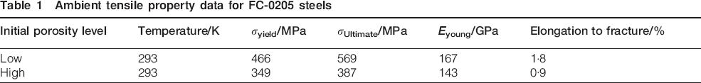
For robust model predictions, the MSF model requires correlation and validation experiments to confirm its applicability to powder metal structural components. For model correlation, uniaxial fatigue experiments were conducted on smooth cylindrical fatigue specimens under constant amplitude loading at room temperature (∼25°C) in laboratory air with 45–60% relative humidity. A water atomised iron powder, Atomet 1001, from Quebec Metal Powders was the base iron powder for the FC-0205 material used in this study. A nominal composition of 2 wt-%Cu, 0·05 wt-% graphite, and balance iron was blended and binder treated and were pressed and sintered into rectangular compacts with sintered densities of 6·35 g cm−3 (we define these as ‘high porosity’ for this study) and 7·05 g cm−3 (we define this as ‘low porosity’ for this study) via a proprietary process developed by Metaldyne, LLC. 22 Table 1 lists the tensile mechanical property data for the high and low porosity material used in this study. The decrease in elastic modulus due to the porosity correlates to previous published data. 23 The LCF specimens were machined from sintered blanks with an average length of 123 mm, an average width of 16 mm and an average thickness of 22 mm. The specimen design was based on ASTM standard E606, 24 utilising a gage section diameter of 6·25 mm.
Ambient tensile property data for FC-0205 steels
Fatigue testing
Testing was conducted on an 88 kN MTS load frame. An MTS fatigue rated knife blade axial extensometer was used for measuring the strain. The data acquisition system was set to record the data logarithmically and linearly for the load frame. Loading was applied under strain control with a completely reversed strain amplitude (R = −1). The strain amplitude was applied first in tension, followed by compression. The strain amplitudes tested for the low porosity specimens were 0·4, 0·3, 0·2, 0·175, 0·15 and 0·1%. The high porosity strain levels were 0·3, 0·2, 0·15, 0·125 and 0·1%. A frequency of 2 Hz was used when testing at strain amplitudes of ≥0·15%. For the lower strain amplitudes, 0·125 and 0·1%, a frequency of 3 Hz was used.
Damage and failure characterisation
A Zeiss Z1 imager optical microscope (OM) provided fracture surface characterisation at the macroscale using bright field reflected light techniques with a z stack feature to account for depth of field issues on the failure surface. A SUPRA 40 field emission gun scanning electron microscope (SEM) from Carl Zeiss was used to analyse the microscale fracture surface morphologies using secondary and backscattered detectors for imaging. A high precision diamond blade cutoff saw was used to section samples parallel to the fracture surface of the cyclically deformed and failed test specimens for analysis in the OM and SEM.
Fatigue modelling
The MSF model was developed for aluminium cast alloys18,25 and further enhanced for magnesium alloys. 26 Since the PM alloys discussed here have similar microstructures and inclusions/defects to cast materials, we surmised that the modelling framework would be sufficiently general to capture the fatigue mechanisms of these various PM alloys. However, we had to make two minor revisions to the model to account for the porosity degradation of the elastic modulus and void coalescence as it relates more directly to the nearest neighbour distance (NND). The MSF model was fundamentally based on micromechanics simulations27,28 and small scale experiments for mechanical properties of small crack growth.28–30 It was further generalised to incorporate material properties and microstructure relations for an incubation model 31 and later modified to increase sensitivity to microstructural features. 4 In this model, high cycle fatigue (HCF) and LCF were both driven mainly by the porosity within the powder metal.
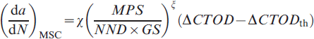
At the pores, the stress field concentration was described by the average plastic strain level that captured the loading history. This constrained microplasticity at the notch root, e.g. pores or particles, and incubated and caused growth of the microstructurally small fatigue cracks during HCF. The growth of microstructurally small cracks (MSCs) was dominated by the crack tip opening displacements, which are proportional to the crack size and (σa)n, where n is a constant.32,33 The long crack propagates to material failure according to LEFM with an associated number of cycles.
34
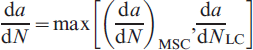
The total fatigue life, defined as cycles to failure, was modelled as the cumulative number of cycles spent in these consecutive stages as follows

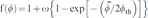
In the MSF model, the total life was divided into three parts, as shown in equation (1). The incubation model was developed with the combination of micromechanics finite element analysis and damage initiation experiments as mentioned earlier
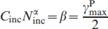
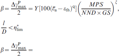
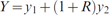
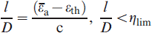
 , ϵth and ϵper are the remote loading strain amplitude (von Mises equivalent strain for three-dimensional loading cases), the strain threshold for damage incubation and the strain percolation limits for microplasticity respectively. D is the average diameter of the inclusions, projected in the direction perpendicular to the loading direction, that incubated the fatigue damage, such as debonded or fractured particles or pores, and l is the plastic zone size in the front of the inclusion projected in the direction perpendicular to the loading. The ratio l/d was used to quantify the micronotch root plasticity due to the inclusions. The limiting factor for this ratio ηlim indicated the transition from the proportional micronotch root plasticity to the non-linear micronotch root plasticity with respect to the applied strain amplitude. The correlation of the local plastic shear strain range with respect to the remote loading strain was developed using finite element simulation, as were the forms of Y, q and ηlim. The parameter Y includes the load ratio effect in terms of
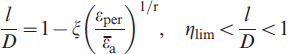
 , where R is the load ratio and y1 and y2 are model constants. Further, when l/d reached its limits, the parameter Y was revised to include geometric effects
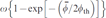
 . Here, we used the estimated fatigue ‘limit’ corresponding to the strain amplitude that gives 107 cycles to failure to mimic the strain threshold for damage incubation. The percolation limit for microplasticity denotes that the incubation becomes an insignificant part of the total fatigue life as the extensive shear localisation becomes dominant in the region near the inclusions. The correlation of the plastic zone size is calculated using the non-local plastic shear strain with the remote loading strain amplitude.
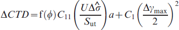

 ; the porosity in front of the crack is defined as

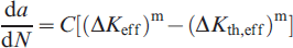
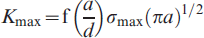
 , U is the load ratio parameter as U = 1/(1+R); and C1, C11 and ζ are material dependent parameters. The modified Paris law, an LEFM based crack growth model, was used for the long crack growth model, that is

Results and discussion
Fatigue behaviour and fractography
Strain–life results for both porosity levels (6·9 and 6·3 g cm−3) are displayed in Fig. 1, which also includes different R ratios. The strain–life behaviour shows that above the plastic strain limit of 0·002 mm mm−1, where ubiquitous plasticity occurs, the two porosity levels are distinctly visible. However, specimens tested below the plastic limit, where failure is dominated by local cyclic plasticity, show unclear distinctions between the two porosity levels.
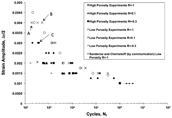
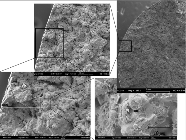
The SEM investigated fracture surfaces of failed specimens in order to determine sources of fatigue crack initiation or nucleation. The fracture surfaces of the fatigue specimens referenced as specimens A, B and C in Fig. 1 are shown in Figs. 2, 3 and 4 respectively.
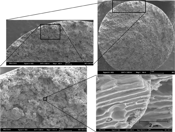
Fracture surfaces of fatigue specimen A
Fracture surfaces of fatigue specimen B
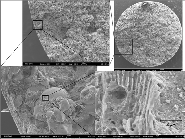
Fracture surfaces of fatigue specimen C
Discontinuities on or slightly below the metal surface are likely responsible for nucleation of fatigue cracks according to Stephens et al., 35 where the reported discontinuities were inclusions, second phase particles, corrosion pits, grain boundaries, twin boundaries, pores, voids and slip bands. Striations that were similar to the appearance of striations reported for a PM steel alloy by Chawla et al. 9 were thought to have been identified. However, after analysis and comparison with the monotonic fracture surface, we observed the same microstructural features on both monotonic and fatigue fracture surfaces. Hence, the ‘striations’ were not striations at all. In fact, the magnified images of the fatigued specimens in Figs. 2–4 reveal some microstructural features that appear to be fatigue striations. However, the same microstructural features are evident when compared to images of the fracture surfaces of the monotonic tensile sample shown in Fig. 5. Thus, it is not conclusive that these microstructural features are fatigue striations. As such, the determination of the location of crack initiation from analysing the fatigue striation patterns is hindered by the lack of clear and concise striations on the fatigue specimen's fracture surface.
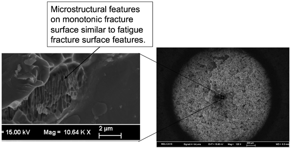
Monotonic tension specimen reported by Allison et al. 36 with microstructural features similar to uniaxial fatigue specimens
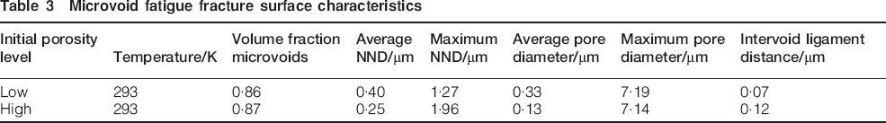
The microstructure quantifications of the fatigue fracture surfaces are provided for the macrovoids and microvoids in Tables 2 and 3 respectively. The characteristics macrovoids and microvoids were determined using an in house image analysis software.36,37 A considerably lower volume fraction for the macrovoid fracture surface is shown in Table 2 when compared to the microvoid characteristics of Table 3, while there is not much difference between the low porosity specimens’ and high porosity specimens’ volume fractions. The average NND, the distance between the centre of two pores, and average pore diameter are lower for the specimens with the higher initial porosity at both length scales. Macrovoid quantification of the maximum NND at the macroscale displays a greater value for the low initial porosity specimens, while the opposite trend is observed at the microscale. Fracture surfaces of the macrovoid showed the high initial porosity specimens containing the larger maximum pore diameters, while the opposite was seen at the microvoid level. The microvoid fracture surfaces had a larger value of intervoid ligament distance, the distance between the closest edges of two neighbouring pores, in the higher initial porosity specimens.
Macrovoid fatigue fracture surface characteristics

Microvoid fatigue fracture surface characteristics
Model correlation
As shown in Fig. 6, the MSF model was correlated to the lower and upper bounds of the fatigue life determined from strain controlled low cycle fatigue tests on both high and low porosity specimens. The correlation to the experimental results is based on standard mechanical properties and quantifiable microstructural features for the MSF constants provided in Appendix. As presented earlier, total fatigue life comprises the number of cycles associated with crack nucleation, microstructural small crack growth and long crack growth. We note that previous modelling correlations of cast and wrought aluminium and magnesium alloys were based on experimentally observed stages of fatigue damage. However, as we observed in this study, the fractography analysis strongly suggests that the MSC growth stage is not likely present in this PM material. As such, the dominant fatigue stages are crack nucleation and long crack growth. We also acknowledge that a large degree of void coalescences occurred, leading to rapid crack growth. This combination of crack nucleation and crack coalescence is similar to multisite damage observed in many cast aluminium alloys. The approach in the MSF model in addressing the coalescence is captured in the small crack stage through the porosity equation
 and the NND term included in equation (7). Ironically, it is the porosity and NND that lead to rapid small crack growth, resulting in a negligent number of cycles for this fatigue stage.
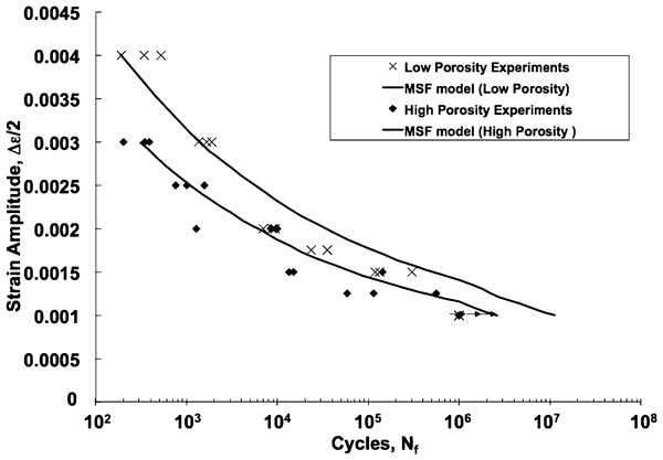
Strain amplitude versus cycles to failure data and best fit relationships from results of fatigue tests on low and high porosity test specimens
The correlation of the upper and lower bounds is mainly achieved through the differences in porosity level. The change in the porosity level leads to an increase in the local plastic shear strain at the macropores. This increase in local plastic strain reduces the incubation life, resulting in an overall diminished number of cycles to failure. The secondary effect leading to differences in fatigue behaviour is the NND. As the porosity increased, the NND naturally decreased, where a reduction in the NND leads to increased crack nucleation and coalescence. Thus, this porosity and NND effect is observed in the MSF correlations presented in Fig. 6 and is confirmed by the fractography analysis.
Lastly, it is important to emphasise that the correlation of the MSF model to the experimental test results performed on the PM material in this study employs identical model parameters. The only differences in the model parameters are the mechanical properties and microstructure features. This is a key point in modelling fatigue damage when the mechanical performance is significantly affected by changes in microstructure. In fact, this modelling paradigm is consistent with the recent integrated computational materials engineering strategies. While it was not the scope of this project, all of the modelling parameters can be determined through lower length scale numerical simulations as part of multiscale approach.
Conclusions
Results from uniaxial fatigue experiments conducted on specimens with low and high initial porosity levels were used to calibrate and validate a microstructurally based MSF model for a powder metal FC-0205 steel alloy. The strain–life behaviour from the experiments displayed that, above the plastic strain limit of 0·002 mm mm−1 where ubiquitous plasticity occurs, the differences in the results from the two porosity levels were distinctly visible. However, specimens tested below the plastic limit, where failure was dominated by local cyclic plasticity, showed unclear distinctions between the different porosity levels. Analysis of the fracture surfaces did not clearly depict the presence of striations.
Material model constants were determined using experimental and microstructure data that allowed for satisfactory prediction of strain–life relationships for the different porosity levels. The number of cycles for incubation of the fatigue crack was dominant, while the number of cycles for the MSC regime was negligible because, as the crack first initiated, the contribution of pore size, which was relatively large, induced longer crack behaviour. Finally, this study clearly showed that using models and methods that do not include the heterogeneities of the microstructure within the boundary value problem can produce erroneous results. Alternatively, when the heterogeneous microstructure is included in the finite element simulations, the fatigue life can be predicted.
Footnotes
Acknowledgements
This research was funded by US Automotive Materials Partnership (AMD410) contract no. FC-26-02OR22910 with guidance from H. I. Sanderow (Center for Powder Metallurgy Technology), R. A. Chernenkoff (Metaldyne), P. Rosa (DaimlerChrysler), S. G. Wakade (GM Powertrain) and G. Weber (Ford Motor Company). We would also like to acknowledge the Center for Advanced Vehicular Systems at Mississippi State University for supporting this work. Discussions and guidance about this research from Dr R. German (SDSU) to Dr Allison are gratefully acknowledged. Permission to publish was granted by Director, Geotechnical and Structures Laboratory.