
Abstract
There is considerable interest in reducing the volume of gas escaping around the blade tips in a gas turbine by fixing an abrasive, such as c-BN, onto the blade tip with an alloy, such as MCrAlY. Abrasion testing at 1100°C showed that the MCrAlY deformed and the abrasive particles oxidised. The shear stress in the MCrAlY was estimated by finite element methods to be in the range of 5–30 MPa, while measurements of the frictional heating suggest the local temperature is between 1100 and 1200°C. Creep testing showed that conventional MCrAlYs were too weak under these conditions. However, higher strengths were obtained using a continuous reinforcing phase together with NiAl. An Al2O3/ZrO2 abrasive was investigated as a more oxidation resistant abrasive. In this case, reaction with the MCrAlY caused Ni to diffuse into the abrasive forming layers of NiO, weakening the particles and causing premature failure.
Keywords
Introduction
The efficiency of gas turbine engines is highly dependent on the clearance between the rotating blades and the surrounding shroud. If the clearance is too great, some of the air moving through the turbine can escape over the top of the blade and does no work, reducing the efficiency. 1 Preventing such losses, sealing, is particularly important in the high pressure turbine. 2
Sealing can be achieved in two ways. In the first, the blade has a flattened end, known as a shroud, which forms a circumferential link with adjacent blades, giving a high sealing efficiency.3,4 However, the shroud increases the stresses acting on the blade, effectively reducing the turbine entry temperature or decreasing the creep life, 5 so that despite the improved sealing, removing the shroud may offer benefits. In this case, sealing is achieved by cutting a track through a porous ceramic abradable. 5 To ensure both effective cutting and also that the blade tip is protected from wear, abrasive particles, typically c-BN, are fixed to the blade tip using an MCrAlY, known as the anchor phase, where M can be Ni, Co or a Ni/Co alloy. 4
The track in the abradable is cut when the engine is first run, but as repeated cuts and protection from wear are required throughout the lifetime of an engine, 2 the blade tip should retain its cutting power for prolonged periods. However, the blade tips are exposed to temperatures of at least 1000°C, whereas c-BN is known to oxidise at these temperatures. 6
Oxide abrasives, which form the great bulk of the commercial abrasives market, would seem to be an obvious choice. However, some early experiments 7 suggested that they performed poorly when compared with c-BN and SiC, with a strong correlation between an abrasive's cutting ability and its melting point. ZrO2, stabilised with Y2O3, performed best, while Al2O3 was hardly able to cut at all, which is surprising as Al2O3 is harder than ZrO2, particularly at elevated temperatures.8,9 These experiments were carried out on a rig, 10 where the abrasive tip is rubbed against an abradable at speeds of up to 430 m s−1. The abradable was heated constantly using a gas flame to 1200°C. The abrasive tip was heated only as it entered the flame, and cooled after leaving it, so that the behaviour would tend to be that associated with high speeds, rather than high temperatures. However, the rates of both oxidation of the c-BN and creep of the MCrAlY will increase exponentially with increasing temperature.
This paper therefore focuses on understanding the effects of temperature on the material properties required for the MCrAlY anchor phase and whether these are likely to be met by existing MCrAlY type materials and also to understand why the cutting behaviour of oxide abrasives, particularly those containing Al2O3, appears to be so poor.
Experimental
Abrasion testing
Abrasive tips ∼20 mm long and ∼2·5 mm square were cut from larger samples. The tips had abrasive particles of either c-BN, Si3N4 or Cr coated SiC fixed to an Inconel 718 tip with an MCrAlY matrix electrodeposited by entrapment plating. 10 For c-BN and Si3N4, the anchor phase was a CoNiCrAlY. 11 However, for the Cr coated SiC, a CoCrAlY anchor phase was used to limit reaction. A eutectic Al2O3/ZrO2 was also investigated with a NiCrAlY anchor phase.
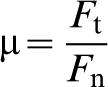
Abradables were made by plasma spraying ZrO2 containing ∼8 wt-%Y2O3 (YSZ) onto 3 mm thick mild steel discs of 50 mm diameter. Abrasion testing was carried out at 25, 900 and 1100°C for times of up to 1 h, under a load of 15 N and at a linear velocity of 1·3 m s−1 (see Fig. 1). These experiments were also used to measure the temperature increase associated with the frictional rubbing. To compare these with predictions, such as those by Jaeger,12,13 the coefficient of friction μ was required. This is given by
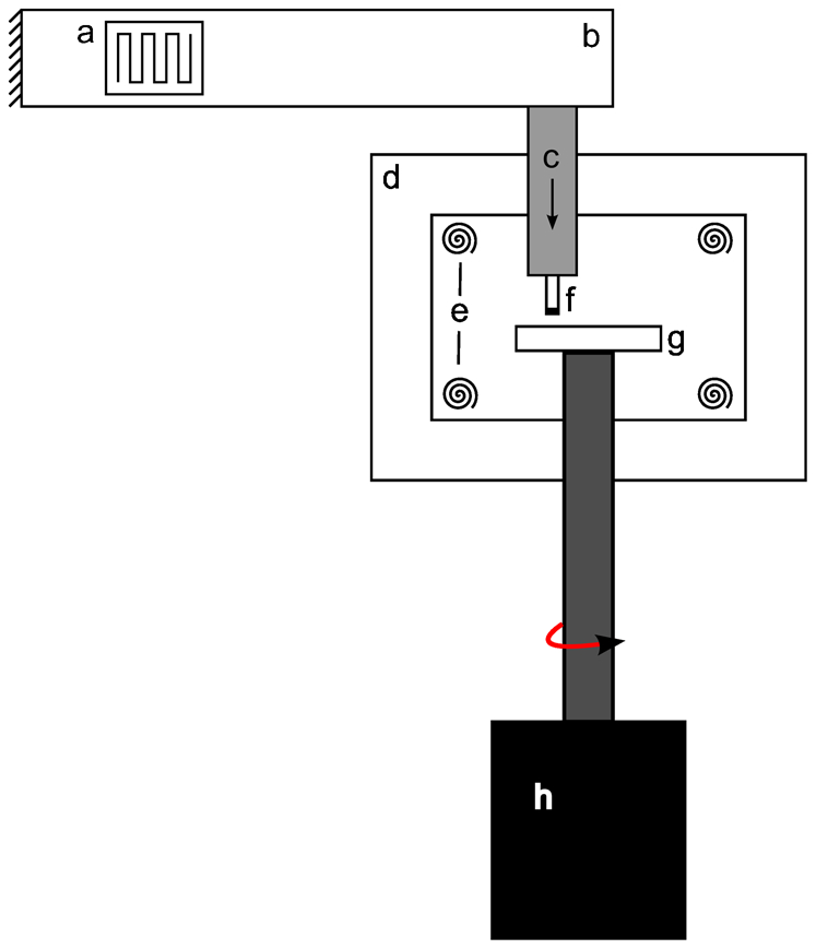
a strain gauge; b loading arm; c pneumatic loading arm; d furnace; e heating elements; f abrasive tip; g abradable disc; h motor
Finite element analysis
Finite element methods (ABAQUS 6·11-1) were used to estimate the shear stresses that develop in the MCrAlY anchor phase during abrasion. The particle shape was taken as square with diagonals of 200 μm, 14 typical of the c-BN particles commonly used, and embedded in MCrAlY to depths of 50, 100 and 150 μm, so that the exposed height of the particle was 25, 50 and 75% of the particle diagonal. The loads applied were obtained from the abrasion tests, where a tangential force of 12 N was measured for a tip under a normal force of 15 N, with a cross-sectional area of 8·64 mm2 with 12·5 particles mm−2. For simplicity, it was assumed that the load experienced by the tip was focused on the leading edge. 15 This was taken as being 0·2 of the tip area, and the 22 particles were taken as sharing the overall tangential force. Each particle therefore experienced a tangential force of 0·56 N. This was applied as a surface traction over the first four elements of the c-BN particle, using a Young modulus for c-BN of 909 GPa and Poisson ratio of 0·14, 16 and for the MCrAlY, a Young modulus of 110 GPa and a Poisson ratio of 0·33. 17
Creep testing
Foils (400 μm thick) of a CoNiCrAlY were loaded at stresses of 2 to 14 MPa and temperatures ranging from 1050 to 1200°C. The strain was measured using digital image correlation. 18 The creep testing was performed in air, and the foils were heated by induction heating, so the full gauge length of the sample could be viewed throughout the duration of the creep test.
Alloy preparation and characterisation
A composition of 45·3Ni–44·7Al–10Ta (at-%) was prepared by arc melting, which was predicted to have a volume fraction of Laves phase of ∼0·3. The alloy was then homogenised for 24 h at 1300°C. Three-dimensional ion beam tomography 19 was used to study the distribution of the Laves phase.
A composition of the pure Laves phase 33Ni–33Ta–34Al was also prepared by arc melting to measure its thermal expansivity. The alloy was annealed at 1300°C for 1 h before testing. However, as seen in previous work, there was still a small fraction of NiAl remaining. 20 Thermal expansion measurements were performed on a dilatometer (Netzsch Dil 402 C) under flowing argon.
Results and discussion
Problems of abrasion
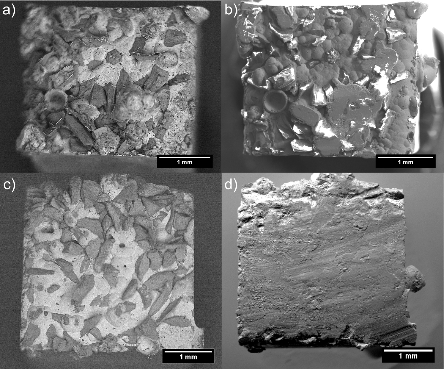
Figure 2a and b shows a c-BN abrasive tip before and after rubbing against a ZrO2 abradable at room temperature. Most of the c-BN abrasives survived. However, more damage was sustained after exposure at temperatures as low as 900°C (Fig. 2c and d) with adhesion of abradable debris to the surface of the tip, as well as fracture of the abrasive particles. When the temperature was increased to 1100°C, there was also extensive plastic deformation of the anchor phase in only 10 min, causing loss of abrasive due to deformation of the anchor phase (Fig. 2e and f) as well as abrasive fracture. This damage started by the growth of cracks, which were at 60° to one another, reflecting the symmetry of the c-BN. Such cracks have been observed elsewhere. 6 Although the conditions used in the tests here are at much lower speeds than those in the turbine, the adhesion of abradable debris to the abrasive tip has been seen in the high speed abradability tests, albeit at lower temperatures. In addition, extensive deformation of the abrasive blade tips is commonly seen in engine tests. It is therefore tentatively suggested that the results obtained here are representative of engine conditions, although considerably more work is required to confirm this.
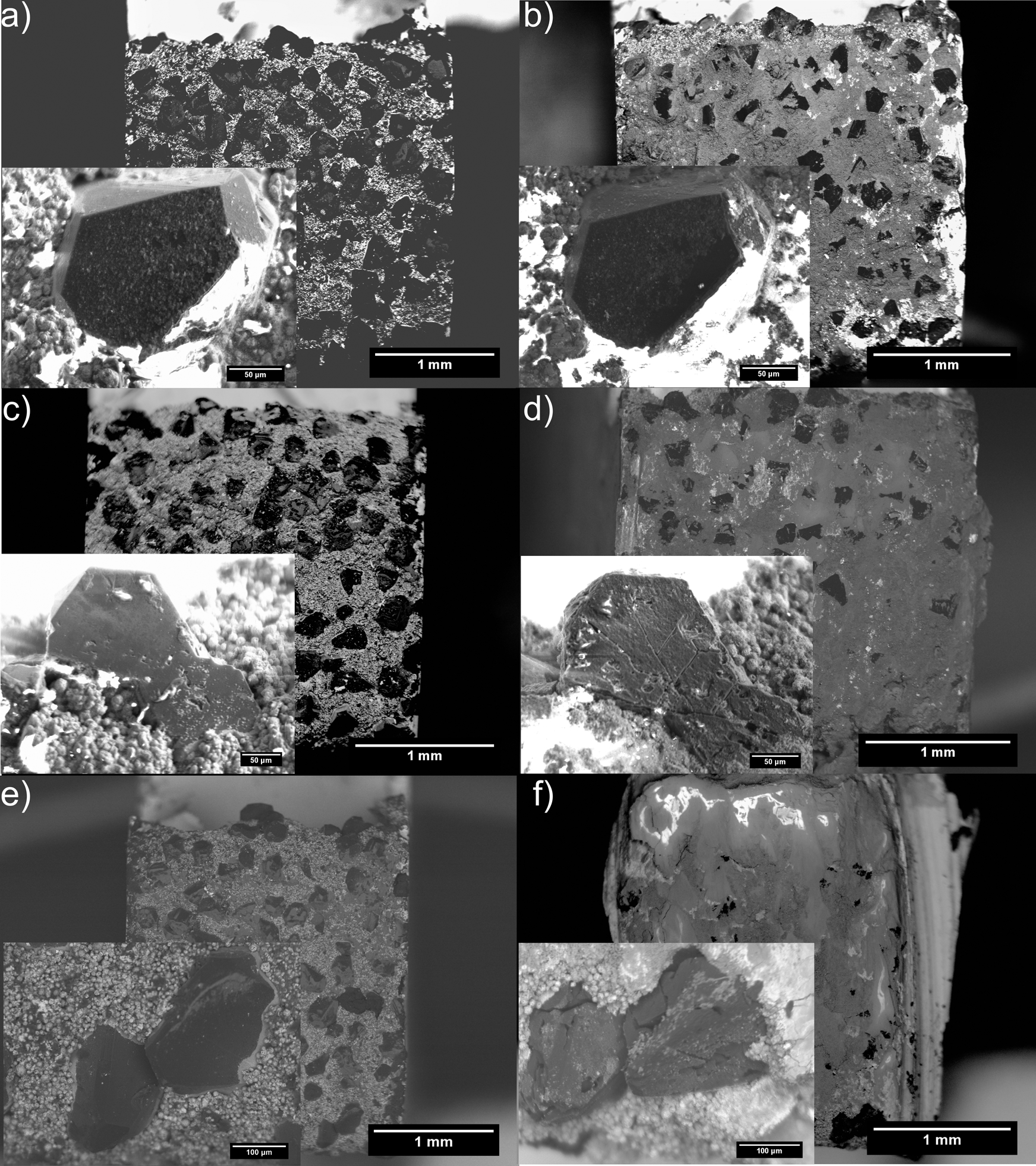
Electron backscattered images of abrasive tip a before and b after abrasion at 25°C, c and d 900°C and e and f 1100°C; inset shows same abrasive particle before and after abrasion
The oxidation of the abrasive and the deformation of the anchor phase suggest that if an abrasive tip is to have a lifetime of more than a few minutes, the oxidation resistance of the abrasives must be improved and the strength of the MCrAlY anchor phase increased.
Developing anchor phase
The finite element calculations predicted that the highest shear stresses in the anchor phase would increase from 5 to 30 MPa, as the exposed height of the particle was increased from 25 to 75%. At 50% exposure, the predicted shear stress was 11 MPa.
The temperature around the blade tip is thought to be ∼1000°C.
21
However, as the abrasive tip is likely to be rubbing the abradable, frictional heating may increase this. Temperature measurements in the abrasion testing showed that this increase, due to friction, varied from ∼150°C at room temperature, but decreased to ∼50°C, as the ambient temperature was increased to 1200°C (Fig. 3). This is of the same order as the values predicted, also shown on Fig. 3, using the simple one-dimensional expression of Jaeger,12,13 given by
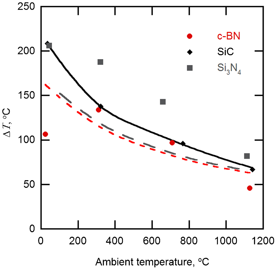
Temperature increase due to frictional heating during abrasion versus ambient temperature for c-BN, SiC and Si3N4 abrasives; solid, long dashed and short dashed lines are predicted temperature changes, from equation (1), for SiC, Si3N4 and c-BN abrasives respectively
Most of the terms in this expression can be measured, including the normal force Fn, the friction coefficient μ, the velocity v and the area A, the nominal area of the tip and l the diffusion distance. The value of K, the thermal conductivity of the tip, was set equal to that of Inconel 718, 22 which formed the main part of the tip as its thermal conductivity was much less than that of the c-BN abrasive. 23 The partition coefficient α, gives the fraction of heat that is transferred to the tip. As the thermal conductivity of the c-BN/superalloy tip K is much greater than that of the porous zirconia abradable, 24 the heat will flow predominantly into the pin, that is α = 1. The decrease in the temperature can now be understood in terms of the increase in the thermal conductivity of Inconel 718 from 11 W m−1 K−1 at room temperature to 28 W m−1 K−1. These estimates lend further support to the idea that the temperature at the abrasive tip is likely to lie in the region of 1100–1200°C, 0·8–0·9 of the melting point of most MCrAlYs. 25
To investigate the suitability of MCrAlYs in this application, constant load creep tests were carried out on a CoNiCrAlY over the temperature range of 1050–1200°C. The data obtained are shown in Fig. 4. The data obtained here at 1050, 1100 and 1200°C were consistent with the data obtained elsewhere at lower temperatures.26–29 From Fig. 4, it can be seen that at 1050°C, and over the range of stresses of interest here, MCrAlYs will creep at rates from 10−5 to 10−3 s−1. If it is assumed that the anchor phase can withstand a strain of 0·1 before the abrasive is lost, then the abrasive tip will withstand a cut lasting between 104 and 102 s. Although rather short at the higher stresses, this is not unreasonable, suggesting that at 1050°C, MCrAlYs should have just sufficient strength.
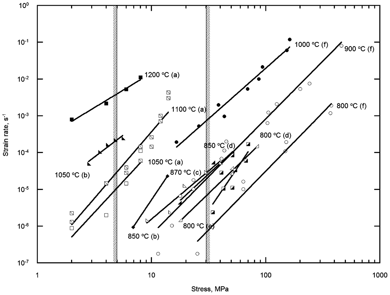
However, if frictional heating raises the temperature to 1200°C, the creep rates lie between 3×10⁻² and 10−1 s−1. In this case, the time before failure lies between 30 and 1 s, suggesting that failure would be almost immediate. This was qualitatively consistent with the observations in the abrasion tests here. It is clear that if frictional heating was important, as was observed, then MCrAlYs in their present form are too weak for this application.
The strength of MCrAlYs can be increased either by alloying with solutes or by adding dispersions of oxide particles. 30 In both cases, improvements were observed, though by 1000°C, these were minimal in the case of the solutes and even where a volume fraction of 0·3 of oxide particles was introduced, the strength at just 1000°C was increased from 6 to only 30 MPa.
A successful anchor phase material also requires oxidation resistance and compatibility with the underlying blade material, in this case CMSX-4. NiAl based materials are therefore attractive, particularly as there is already extensive experience in their use as oxidation resistant coatings. 31 Unfortunately, NiAl is relatively weak and brittle. 32 Strengthening with both solutes and dispersions of second phase particles are possible, 33 but as with MCrAlYs, the improvements tend to be minimal >1000°C.
One way of overcoming this problem is to use a continuous hard phase, embedded in NiAl to give the oxidation resistance, so that the strength of the overall body is determined by the strength of the hard phase. Although various possibilities exist, a NiAl strengthened with a continuous hexagonal (C14) Laves phase, NiTaAl, was investigated. 34 Serial sectioning by focused ion beam milling showed that the Laves phase was continuous (Fig. 5a). The overall alloy had a compression strength of 280 MPa at 1200°C (Fig. 5b), approximately consistent with the data obtained by Zeumer and Sauthoff. 34
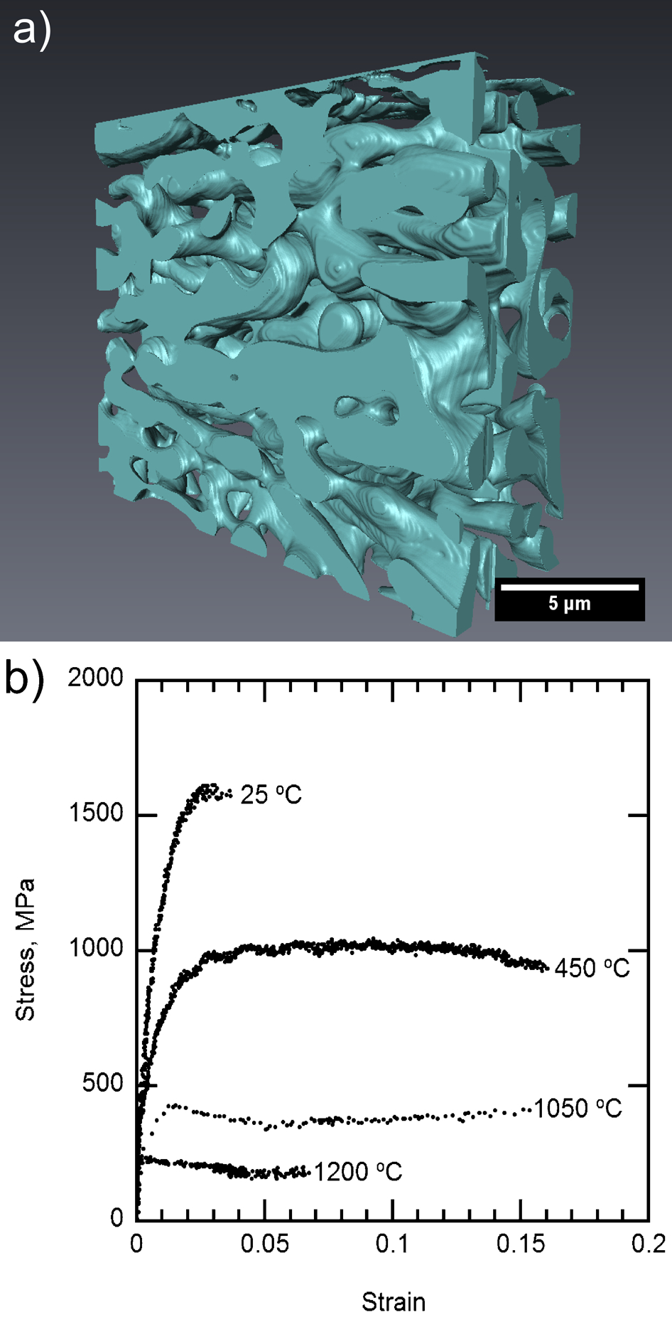
a connected network of reinforcing Laves phases within NiAl and b variation in compressive strength with temperature
However, such materials are much more brittle than the existing MCrAlYs. In the case of the oxidation resistant coating that is applied to the sides of the blade, a crack that forms in the coating as the blade undergoes creep deformation can grow into the turbine blade. 35 However, if the anchor phase is only being used on the blade tip, the driving force for cracking can only come from thermal expansion mismatch between the blade material and the coating. Preventing cracking might therefore be achieved by minimising the expansion mismatch.
The range of expansivity αc of the NiAl–NiTaAl alloy was estimated using the expression
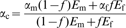
This gave expansivities of the NiAl–NiTaAl material here between 15·2 and 19·1×10−6 K−1 over the temperature range 350–950°C, compared with between 13·9 and 21·5×10−6 K−1 for CMSX-4, 38 so that expansion matching is possible, as shown in Fig. 6, where it can be seen that the expansivities can be matched at a volume fraction of Laves phase that allows the high temperature strength to be retained.
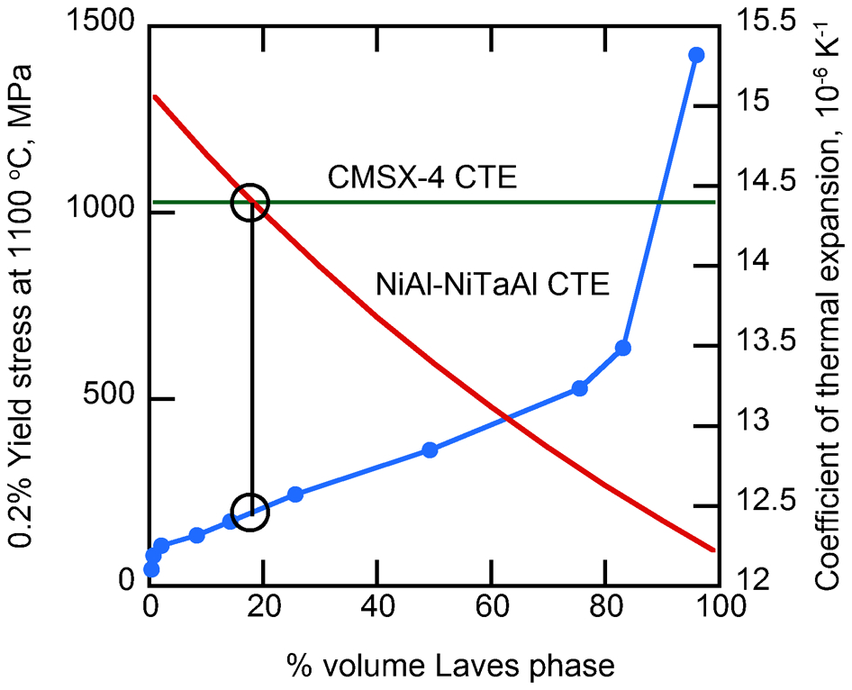
Variation of yield strength of NiAl–NiTaAl alloy with volume fraction of Laves phase and comparisons of coefficient of thermal expansion
Developing oxidation resistant abrasive
The initial abrasion experiments showed that all of the non-oxide abrasives oxidised and that this was particularly marked in the c-BN. The most obvious oxidation resistant abrasive would be an oxide. Of the common oxides, alumina is the most resistant to chemical attack in the turbine atmosphere. 39 Some experiments have been carried out on oxides. 7 However, their cutting ability was worse than that of c-BN and scaled with the melting point, an observation that has also been made for polishing abrasives. 40 ZrO2 appeared the most promising, and Al2O3, under the test conditions used, had almost no cutting ability at all, despite being harder than ZrO2, particularly at elevated temperature. Apart from the observation of the lower melting point of Al2O3, no explanation of this behaviour has ever been made.
To see what difficulties might arise with oxides, the abrasion behaviour of a eutectic Al2O3/ZrO2 was investigated using the same experimental procedures as the non-oxide abrasives. At room temperatures, like the c-BN, the abrasive survived with little damage (Fig. 7a and b). However, at higher temperatures, the abrasive was rubbed flat with the surface of the anchor phase (Fig. 7c and d). Cross-sections through the abrasive tip were consistent with the abrasive fracturing with no evidence of any plastic deformation. It was also observed that NiO had formed around particles exposed at the surface. As this did not form around those embedded completely within the anchor phase, this must be associated with oxygen ingress along the particle/matrix interface. NiO grew into the particles along the boundaries of alumina that separated the groups of Al2O3/ZrO2 platelets (Fig. 8), presumably weakening the particle and causing premature failure. It is suggested that this was the reason for the poor performance of Al2O3 abrasives, rather than simply their low melting point.
Al2O3/ZrO2 eutectic abrasive particles a before and b after abrasion at 25°C, and c before and d after abrasion at 1100°C
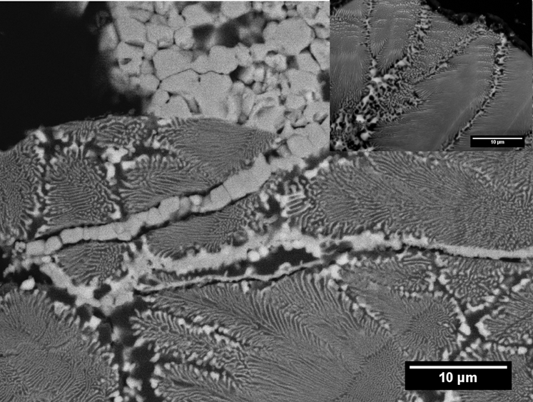
Al2O3/ZrO2 eutectic abrasive particles after abrasion at 1100°C for 2 min, showing layers of NiO that have grown into particle, possibly weakening abrasive particles
Conclusions
It has been shown that the shear stresses developed during cutting are approximately 5–30 MPa. Although not large, conventional MCrAlY materials are likely to be too weak to act as an anchor phase in an abrasive tip at the temperatures that are likely to be required. However, higher strengths can be obtained using a continuous reinforcing phase together with NiAl to ensure sufficient oxidation resistance and compatibility with the turbine blade material.
Alumina containing abrasives react quickly with the NiCrAlY anchor phase, within a few minutes, giving rise to the growth of NiO layers within the abrasive particles. It is suggested that it is the chemical interaction of the abrasive and the anchor phase that might be causing Al2O3 to have a much lower cutting ability than ZrO2 despite the higher hardness of Al2O3.
Footnotes
Acknowledgement
This work was carried out with support from the EPSRC/Rolls-Royce Strategic Partnership (EP/H500375/1).