
Abstract
It is not the first time that a consortium of steel makers, end users and scientists end up with unique approaches and developments in the physical metallurgy of steels. The present paper reveals the scientific and technological developments of a consortium sharing a common intrigue and interest for a unique microstructure, nanostructured bainite. Also known as low temperature bainite, its unique properties rely solely on the scale of the miscrostructure obtained by heat treatment at low temperature (150–350°C). Careful design based on phase transformation theory, some well known metallurgy facts and the necessary industrial experience were the ingredients for a further step towards the industrialisation of these microstructures.
Introduction
For the last decade, a new variant of bainitic steels, also known as NANOBAIN, has been studied and characterised at different levels. The reported plethora of exceptional microstructural features and their resulting properties, at laboratory scale, rely on the scale of the microstructure, slender plates of bainitic ferrite plates, tens of nanometre thickness, intimately interweaved with retained austenite. One of the biggest achievements was to obtain such microstructure and properties without the need of complex and expensive manufacturing processes, only by tailoring the chemical composition so the homologous temperatures would be as low as T/Tm≈0·25, where Tm is the absolute melting temperature.1,2 The reported mechanical properties3,4 and the impressive improvement in transformation kinetics achieved through different generations of NANOBAIN steel grades 5 were highly appreciated by potential final users; but still, there were some issues to be addressed before further steps towards the industrialisation of such microstructure could be taken.
Thus, during 3 years, a consortium of steel makers, end users and researchers work together on the design of two tailored grades to manufacture two very different components with a nanostructured bainite microstructure:
small component, 20×2×3 cm, heat treated using dry gas technologies, DryBain, 6 with emphasis on its fatigue resistance and strength ultimate tensile strength (UTS) >2000 MPa
large component, 70×40×20 cm, heat treated in salt bath, with emphasis on wear resistance and UTS >1600 MPa.
The present work describes the main work flow, the most relevant achievements and the exceptional results achieved during the duration of the consortium.
Material design
For the alloy design, bainite transformation theory together with some physical metallurgy concepts7,8 has been used; but in addition, there were some very specific industrial demands that needed to be observed, i.e. the microstructure has to be obtained in industrially acceptable times and using inexpensive alloying additions. Therefore, during the theoretical design of the steel grades, the fulfillment of the following premises were sought.
Low transformation temperatures, Bs and Ms, which mainly affect the fraction, distribution, composition and scale of both phases, retained austenite and bainitic ferrite, explaining the palette of mechanical properties.
Suffice hardenability to avoid at all instances transformation during cooling from the austenitisation temperature to the bainite transformation temperature, not only for the possible damage to the final mechanical properties, but also because the whole design process is based on the assumption that austenite has the bulk chemical composition. Thus, if other transformations take place before bainite, the austenite from which it forms has a different composition, and the whole design process is jeopardise. In this sense, especial efforts were carried out in order to define critical cooling rates, especially for the big component.
Acceleration of the transformation kinetics. Unquestionably, this is a major concern in the development and implementation of these novel bainitic steels, because even for the fastest alloys, up to date, it took days for ending the transformation, a time scale that it is just unthinkable from the point of view of production effectiveness.
As stated, when talking about future industrial implementation, the alloys concerned must be cheap to produce if they are not to be limited to niche applications, and elements that have been used in the past for different purposes in these type of alloys, such as Ni for hardenability and Al and Co to accelerate the transformation,1,5,9–12 were not considered during the design process, just aiming for a cheap and lean system, i.e. Fe–C–Si–Mn–Cr. Thus, Co and Ni are ruled out due to the cost of raw materials, and Al for the incompatibility of high additions with cleanliness requirement of ultra high strength steels.
The design process ended up with two sets of alloys: 8 one with a higher C content, the 1C–0·8C family, and another one with lower C, the 0·6C family (see Table 1). All the alloys without exception contain sufficient Si (at least 1·5 wt-) to suppress the precipitation of cementite from austenite. 13 Behind this, there are two reasons: first, cementite is avoided for being a hard and brittle phase that would impair the final mechanical properties, but also, because, as mentioned, the aimed microstructure consists of bainitic ferrite and retained austenite, and cementite, as a C sink, makes austenite more prone to martensitic transformation during cooling after bainitic transformation. 14
Chemical compositions of designed alloys
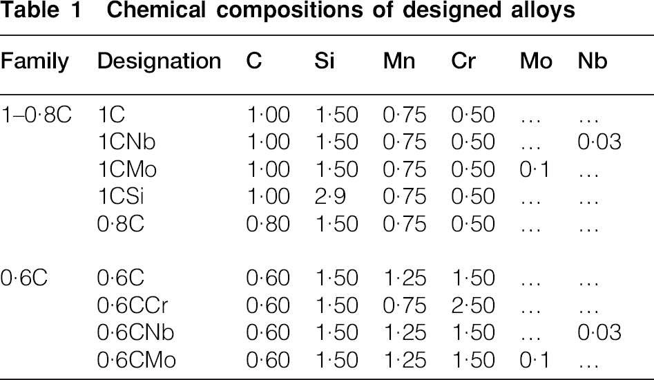
It is well known that low Bs and Ms are easily achieved using high C concentration and, to a lesser extent, solutes such as Mn, Cr. However, as high C content slows down the transformation kinetics, it was also assumed, in some of the alloys, that there is a substantial decrease in the C content down to 0·6 wt-, justifiying both families in Table 1. However, the decrease in the C content needs to be compensated to keep low Bs and Ms temperatures, with higher Mn and Cr contents, when compared with the other alloy families.
As one of the premises during the design process was to use inexpensive alloying elements Co and Al, originally present in one of the first set of NANOBAIN alloys, 5 were completely ruled out from the new system and their accelerating capability on bainitic transformation was compensated by keeping Cr and Mn as low as possible, to maintain the transformation times within the range of the Co and Co+Al alloys, 5 fastest up to date, and, at the same time, to ensure sufficient hardenability to avoid transformation during cooling from the austenitisation temperature to the bainite transformation temperature.
As bainite nucleates in austenite grain boundaries, a further transformation rate increment is possible by increasing the possible potent nucleation sites, i.e. refining the prior austenite grain size (PAGS). The PAGS can be controlled by keeping the austenitisation temperature as low as possible, 5 process parameter or during the alloy design by introducing an element that through the formation of stable precipitates at high temperatures could exert a pining effect on the austenite grain growth, therefore limiting its size. Suitable and well known elements for this purpose are Nb and V. 15 With this purpose in mind, small quantities of Nb, 0·03 wt-, were added in the 1CNb and 0·6CNb alloys.
The scale of the microstructure, i.e. bainite plate thickness, is mainly controlled by the strength of the austenite from where it grows.16,17 The novel approach in the present work was to act directly on the strength of the parent austenite by including strong solid solution strengtheners as Si (1CSi) and Mo (1CMo,0·6CMo).18,19 Keeping in mind the mild retarding effect that Si may have on bainite transformation kinetics, its content was limited 20
Microstructure and properties
Transformation and microstructure
All grades were manufactured at laboratory scale, using vacuum induction melting to produce ingots of 20 or 35 kg. Once solidified, the ingots were reheated to 1200°C (1150°C for the 2·5Si grades) and forged to bars of ∼40 mm diameter. The bars forged were slowly cooled in a furnace to avoid cracking.
High resolution dilatometry was used to track bainitic transformation at different temperatures, and together with a detailed microstructural characterisation, allowed for the selection of the isothermal transformation parameters, time and temperature, most appropriate for the later study of their mechanical behaviour.21,22 Although further details can be found in Ref. 21, it is unavoidable to remark that nanostructured bainite was obtained in all the grades by isothermal transformation in the temperature range of 200–350°C and 240–350°C for the 1–0·8C and 0·6C families respectively; Fig. 1 serves as a typical example of the developed microstructure.
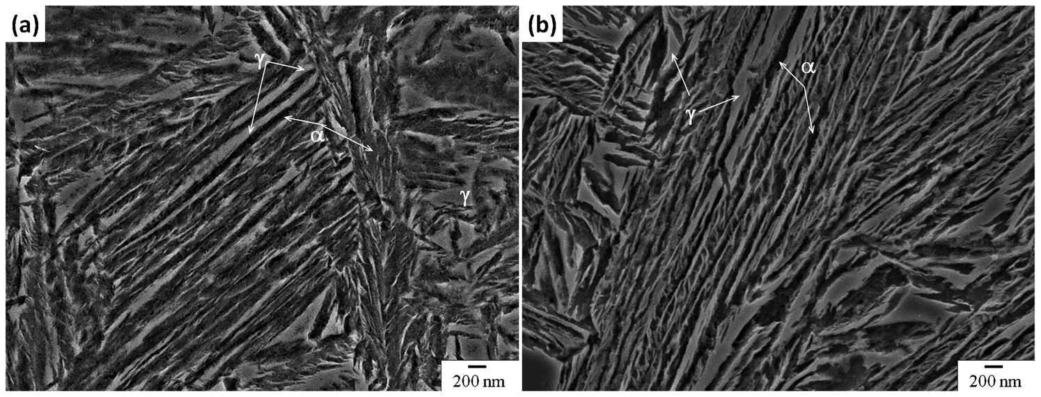
Examples of typical nanostructured bainite microstructure obtained in the 0·8C alloy after isothermal treatment at a 220°C and b 270°C.
The austenitising temperature was adjusted to keep it as low as possible to enhance bainitic transformation, i.e. 950 and 890°C respectively. The obtained microstructure and its evolution with the transformation temperature did not differ from that already reported.1,2,5,9 Bainitic ferrite α is the dominant phase, with fractions Vα exceeding 0·60 and plate thickness tα ranging from 21 to 65 nm. Carbon enriched austenite is the dispersed second phase, with its two very distinguishable morphologies, thin films between the plates of ferrite, also in the nanorange, and blocks separating sheaves of bainite (groups of bainitic ferrite plates sharing a common crystallographic orientation). High magnification observation of the microstructure failed to reveal any cementite, as it is expected from adding 1·5 wt-Si.7,13 As already mentioned, when transformation temperature increases, the general tendency is that both austenite fraction and scale of the microstructure increase.
In terms of kinetics, bainitic transformation becomes sluggish as the transformation temperature decreases (see Fig. 2). In general, and as expected, the main differences when comparing both families, 1–0·8C and the 0·6C, reside in a slower kinetics and thinner scale of the microstructure (Fig. 2). 21 Finally, since an important industrial requirement is that the transformation must be achieved in a realistic time, it is worth noticing that the two approaches used to accelerate the transformation, i.e. chemical composition control and reduction of the PAGS,5,8 lead to a substantial reduction of the transformation time when compared with the best in their class up to date, Co and Co+Al in Ref. 5. For example, for 1–0·8C bainite transformation at 200°C, it takes about 32–55 h, while at 350°C, only a few hours, ∼3–6 h (Fig. 2), times below those reported in Ref. 5, i.e. ∼72 h at 200°C and between 7 and 10 h at 250 and 300°C respectively.
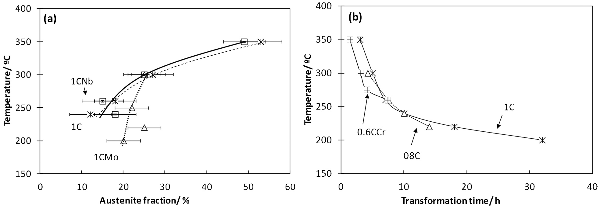
(a) examples of evolution of austenite fraction; (b) time needed to end bainitic transformation
Strength and ductility
As for the tensile tests results, UTS values were always in excess of 2 GPa, with non-negligible ductility. The detailed analysis of the results clearly outlines three groups: 0·6C grades do not exhibit significant difference in tensile properties as a function of composition. However, for the same transformation temperature, higher carbon grades (1–0·8C) exhibit higher tensile strengths (typically >2200 MPa) and lower elongations. A particular surprise is the 1CSi alloy, with extraordinary combination of ductility and strength, ∼12 uniform elongation for a UTS of 2 GPa. 22 As a measure of comparison, the standard grade 100Cr6 does not exhibit measurable ductility when heat treated to 2 GPa and above. At this point, it is necessary to note that tensile specimens were cylindrical, 5 mm diameter, with a gauge length of 12 mm, and reported results correspond to an average of at least four tests.
In carbide free bainitic microstructures, strength is mainly controlled by the amount and scale of the bainitic ferrite, harder phase. Thus, the yield strength correlates well with the ratio Vα/tα (see Table 2 and Fig. 3), the higher the fraction of thinner bainitic ferrite plates, the higher the yield strength (YS), while the exerted effect of the same parameter on the UTS is unclear. In a similar scheme, the attempts to understand the origin of ductility in most specimens have been met with only partial success. Indeed, the selected microstructural parameters (retained austenite or bainite content and lath thickness) fail to provide any indication of the ductility; see the data scatter in Fig. 3b 23 and results shown in Table 2, where similar parameters lead to significantly different ductilities, with a clear difference in results when heat treating at 200/220°C or 250/270°C. As an example, 1CSi exhibits identical retained austenite and bainite lath thickness after heat treatment at 220 and 250°C, but its tensile ductility is entirely different. It has been suggested that retained austenite mechanical stability is the key to the ductility in those microstructures. 23
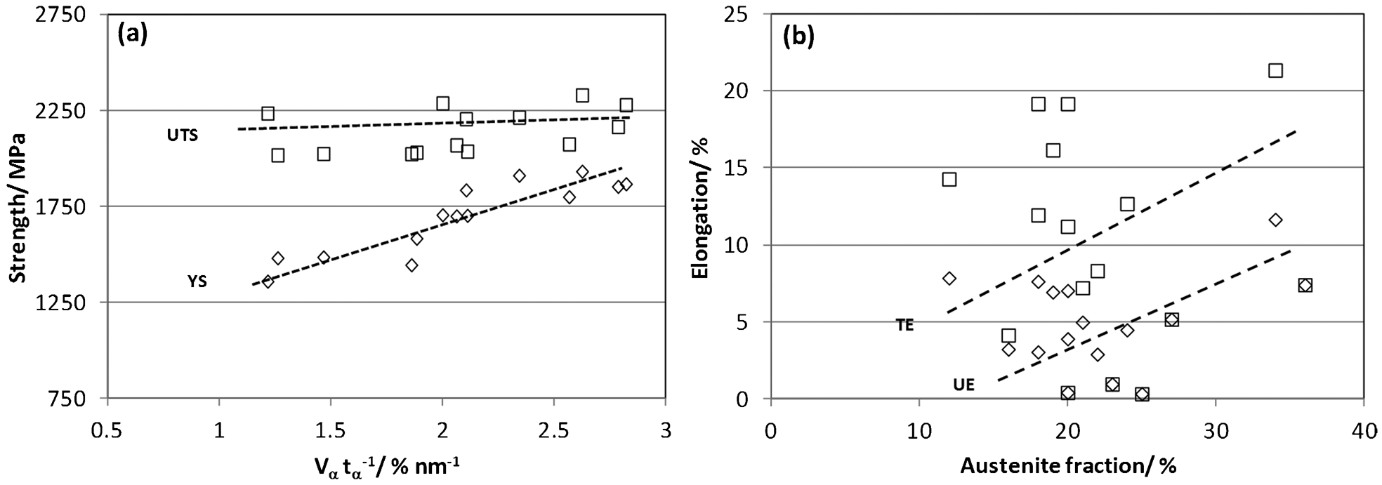
a strength of different samples as function of ratio Vα/tα and b uniform and total elongation, UE and TE respectively as a function of austenite fraction
Tensile test and microstructural characterisation results on selected grades and conditions*
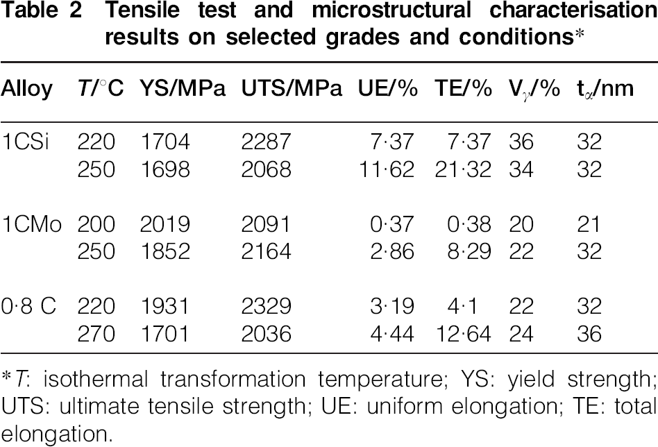
*T: isothermal transformation temperature; YS: yield strength; UTS: ultimate tensile strength; UE: uniform elongation; TE: total elongation.
Wear and toughness
Two types of wear experiments, sliding/rolling wear resistance and high pressure abrasive (HPA) wear resistance, were performed to study the behaviour of the nanoscale bainite under different working conditions.
In terms of the sliding/rolling, there were some studies that indicated the possibility of obtaining good wear performance by carbide free bainitic microstructures,24,25 matching the wear properties of the best pearlitic steels. Chang 26 reported that the ability of bainitic microstructures to withstand large deformations plays an important role on its wear performance, showing that retained austenite transformation induced plasticity effect is beneficial for dry rolling/sliding wear, since it is known to increase plasticity. In line with those findings, Vuorinen et al.27,28 found that the performance of surface hardened steels can be matched by strong carbide free microstructures obtained by isothermal heat treatment of high Si steels; they also reported that at higher transformation temperatures and retained austenite content, the wear rate increased, and results presented in Fig. 4 for the designed alloys are in line with those findings. The wear resistance of the new NANOBAIN microstructures is indeed significantly superior to that of standard material of similar hardness, for example the pair HV/specific wear rate (SWR) for standard 100Cr6 is 714/1·7×10−4 mm3 Nm−1; same material with bainitic microstructure obtained by isothermal transformation at 250 and 300°C reported a pair HV/SWR of 712/1·5×10−4 and 600/2·3×10−4 mm3 Nm−1 respectively. More detailed and comprehensive discussion and results in this matter have been recently published in Ref. 29.
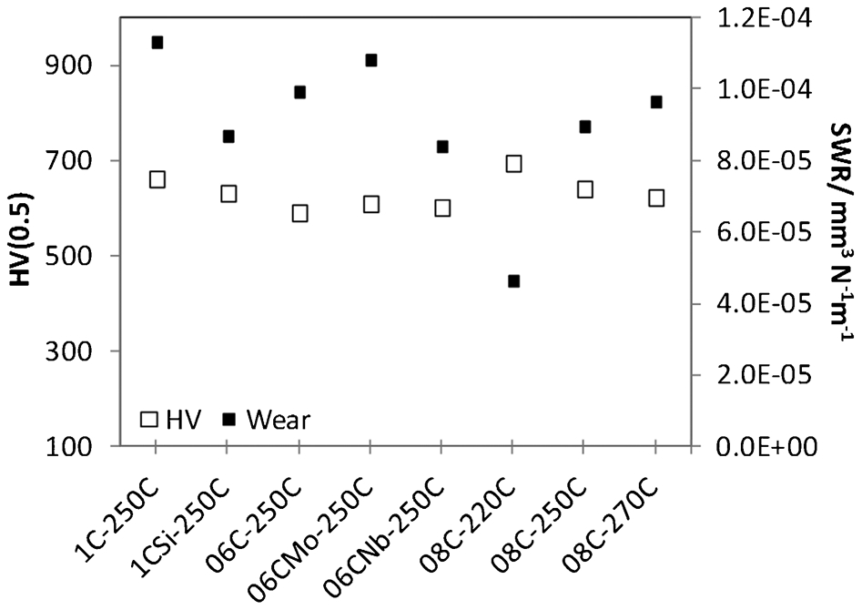
Hardness and SWR for investigated alloys and conditions
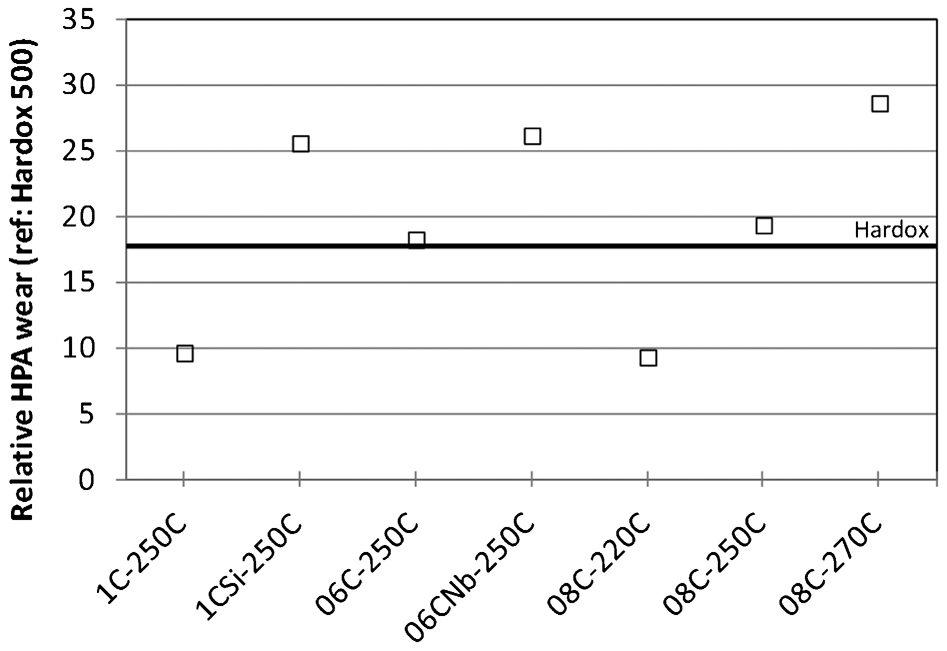
There are significantly fewer data available on the abrasive wear resistance of bainitic structures, and in particular, of carbide free bainitic structures. Some results were found, comparing high Cr cast irons and austempered nodular cast irons.30,31 The austempered nodular cast irons have a bainitic matrix obtained by isothermal transformation. These exhibited abrasive wear resistance similar to that of the high Cr cast irons at a manufacturing cost significantly lower. 30 A study of the mechanisms of abrasive wear suggested that optimum resistance should be obtained for a combination of high strength and toughness. 31 Thus, HPA wear resistance has been studied in conjunction with Charpy-V impact toughness tests. As a reference material, a commercial hot rolled steel Hardox 500 has been used, an abrasion resistant steel typically containing (for the range of thickness of interest) the following: 0·3C–0·6Si–1·6Mn–1·5Cr–1·5Ni–0·6Mo and heat treated to a hardness of ∼500 HV. The final results of the wear tests are shown in Fig. 5, where Charpy-V notch results are also presented. Tests were performed at room temperature according to standard, with an impact force of 300 N.
High pressure abrasive wear and impact toughness results; reference material used for comparison is Hardox 500
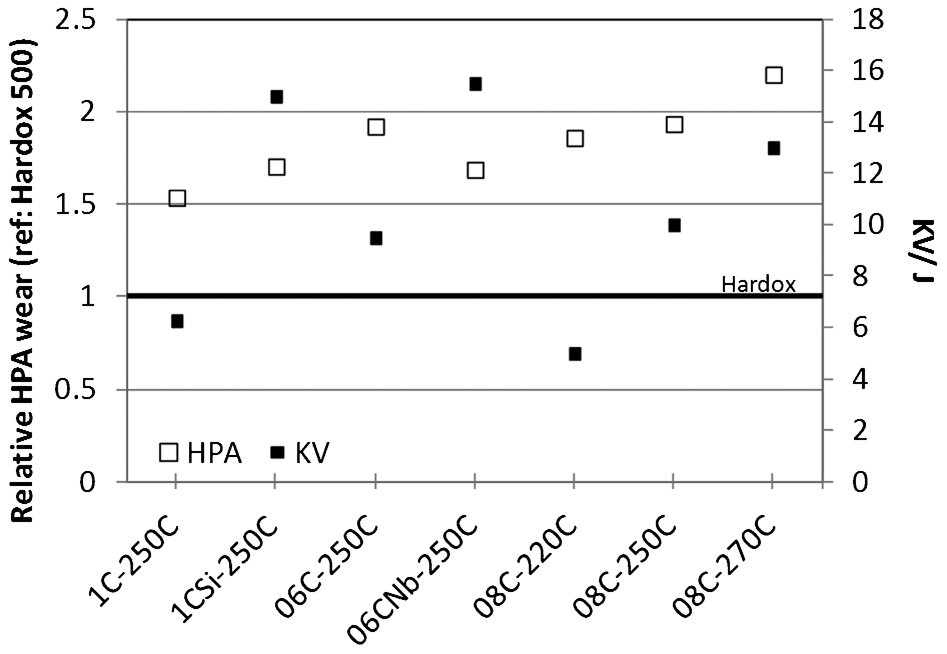
The abrasive wear performances were also promising with performances on par or above that of the current reference for the end user. As for the impact toughness, the highest value was achieved with the 0·6CNb–250°C sample. On the 0·8C grade, the influence on bainite transformation temperature was investigated. Increasing transformation temperature also increases the impact toughness, which is in good correlation with the mechanical properties. In addition, the influence of alloying elements was studied. For the 0·6C concept, Nb addition very much increases the toughness. As well as for the 1C concept, the addition of Si increases the toughness properties. The tests carried out lead to a ranking of the different grades and transformation conditions used. The best high stress abrasion resistance values were achieved by 0·8C–270°C, 0·8C–250°C and 0·6C–250°C; the best impact toughness values by 0·6CNb–250°C, 1CSi–250°C and 0·8C–270°C; and the best combination of those two properties (see Fig. 6) leads to the following ranking: 0·8C–270°C, 0·6CNb–250°C and finally 1CSi–250°C.
Combination of wear and toughness properties; reference material used for comparison of results is Hardox 500
Whether discussing the rolling/sliding or HPA wear tests, the performance of NANOBAIN material has been found to be on par with significantly more expensive alloys such as Hardox, or largely improved compared to bainitic 100Cr6. Performance in rolling–sliding tests appeared to be significantly improved by the presence of significant quantities of retained austenite in the NANOBAIN alloys as opposed to conventional bainite microstructures. The decomposition of this retained austenite could explain the surface hardness measured on NANOBAIN grades, which were significantly higher than those measured on conventional bainitic 100Cr6. 22 In turn, it is shown that surface hardness and wear rate are directly related.
Fatigue
Although without any doubt fatigue is the least investigated of the bainitic steels mechanical properties, from preliminary work on conventional bainitic steels, two conclusions can be drawn: first, that, for an identical cleanliness level, the fatigue resistance is mostly related to its UTS (the higher the UTS, the higher the fatigue resistance is expected to be), and second, that the presence of retained austenite might be playing an important role on fatigue.7,32
Evaluation of fatigue performance was carried out by means of rotation bending on notched specimens. Although results are more difficult to interpret or compare to the vast amount of published data for smooth specimens, there are strong reasons for such decision: first and main, final user applications exhibit stress concentrators; therefore, notched condition is of great relevance; second, notched fatigue may be more sensitive to the presence of retained austenite as the stress concentration under the notch may enhance its decomposition. Finally, the third reason relies on the well established fact that high cycle fatigue performance of high strength material (UTS >∼1200 MPa) is strongly influenced by defects present in the material bulk or surface, and because cleanliness of laboratory casts is not controlled, the use of notched rotation bending specimens is again justified. The combination of rotation bending method and notching would significantly limit the sampling volume since, first, the rotation bending specimens are only at the maximum stress in their outer thickness, and second, the notch will further localise the volume under load along the sample length. Because references were not available in the exact testing conditions used for the rotation bending fatigue, results can only be compared with one another.
A comparison of the fatigue strength achieved on 0·6C and higher carbon material suggests a significant difference between these two types of grades (Table 3), while satisfactory for the former, the fatigue strength of the later was below expectations. Reasons for this are under investigation.
Rotating bending fatigue strength results for 107 cycles*
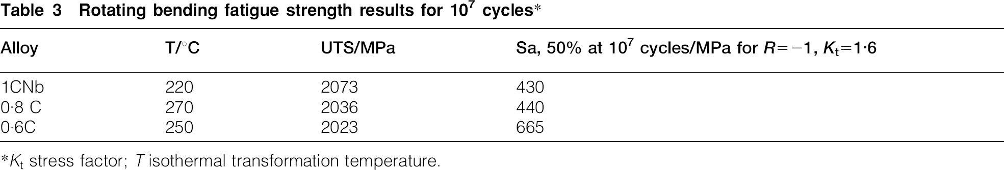
*Kt stress factor; T isothermal transformation temperature.
Industrial trials
As outlined at the beginning of the present paper, the tailored steels had a twofold aim: manufacturing small components using dry gas treatment technology, and larger sections heat treated in salt bath. Both components had also very different mechanical requirements, and the high C family was originally designed for the small component, UTS >2000 MPa with emphasis on fatigue resistance, while the 0·6C family was designed for the big component, UTS >1600 MPa with emphasis on wear resistance.
For the wear component, a preselection of material was carried out based on the best combination of toughness and wear resistance results, Fig. 6. A priori, the following ranking was obtained: 0·8C–270°C, 0·6CNb–250°C and 1CSi–250°C; however, none of both, the 0·8C or 1CSi grades, were designed to offer the hardenability required for the big component, and since major modifications would have to be made to address this issue, it was decided that industrial tests would be carried out using a material similar to 0·6CNb. On the other hand, following the exceptional results achieved on the 1CSi laboratory grade, very high UTS accompanied by equally high ductility, 2 GPa for almost 21 of TE, it was decided to base the industrial heat for the small component on this composition.
In order to anticipate possible problems on the solidification path of both grades, a set of calculations using the Scheil module integrated to the Thermocalc software, allowing for carbon backdiffusion, were performed. While for the 1CSi alloy no problems were anticipated, the precipitation of Nb(C,N) in the liquid was predicted in the 0·6CNb alloy in spite of its low Nb levels. Such precipitates are known for having a detrimental effect on toughness and fatigue. For this reason, it was proposed not to use this element in the industrial heat, and the influence of V was investigated instead. The calculated phase stability for this composition suggests that V(C,N) will precipitate in significant quantities below 1000°C, providing the grain boundary pinning effect initially sought through Nb additions, all the more since austenitising will typically be carried out at temperatures around 850–950°C.33–35 Because of the significant difference between 0·6CNb (selected model alloy; Table. 1) and the aimed composition for the industrial heat (see Table. 4), it was necessary to confirm through a laboratory heat that parameters of interest were similar to those reported on the 0·6CNb alloy. The critical cooling rate was estimated to be sufficient for the big component fabrication and in terms of transformation kinetics, it was similar if not faster compared to 0·6CNb,subsequent characterisation also revealed very similar microstructures and properties.
Chemical compositions of industrial grades
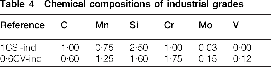
A 100 t industrial heat of the 0·6CV-ind alloy was manufactured. It was cast as 7·2 t ingots and hot rolled to 480×480 blooms. These were later reheated and hot rolled to a diameter of 300 mm, finally and for manageability purposes, the material was subjected to tempering for 6 h at 680°C. For some of the tests, some of the materials were hot rolled to a diameter of 120 mm. The 1CSi-ind was manufactured by ingot casting, and in comparison with the 1CSi laboratory cast, Cr has been increased to enhance hardenability, and Si decreased to reduce manufacturing difficulties.
Both industrial heats lead to a number of difficulties during manufacturing. Those encountered on the 0·6CV were mostly related to the high hardenability of the material. These difficulties imply that hot rolling to small diameter or manufacture of small size components will require special care to avoid air hardening, but in all cases can be addressed successfully. In contrast, difficulties with the 1CSi grade included not only the risk of air hardening for small components but also mostly issues with surface quality and very poor ductility in the as rolled condition
Before moving to actual demonstrator or components, a campaign of laboratory test were performed, and the results thus obtained are gathered in Table 5. Microstructural characterisation revealed that the developed microstructure was, as expected, retained austenite and nanoscale bainitic ferrite plates, and similar to that obtained at lab scale. Consequently, the tensile tests, YS and UTS, were similar if not identical to those achieved on laboratory heats. Uniform elongation was also similar to results achieved on laboratory casts, and the exceptional combination of strength and ductility (above 10 uniform elongation for 2 GPa) was once again achieved with 1CSi heat treated at 250 or 270°C (see Table 5).
Microstructural and mechanical properties characterisation results performed on industrial grades treated at different temperatures.
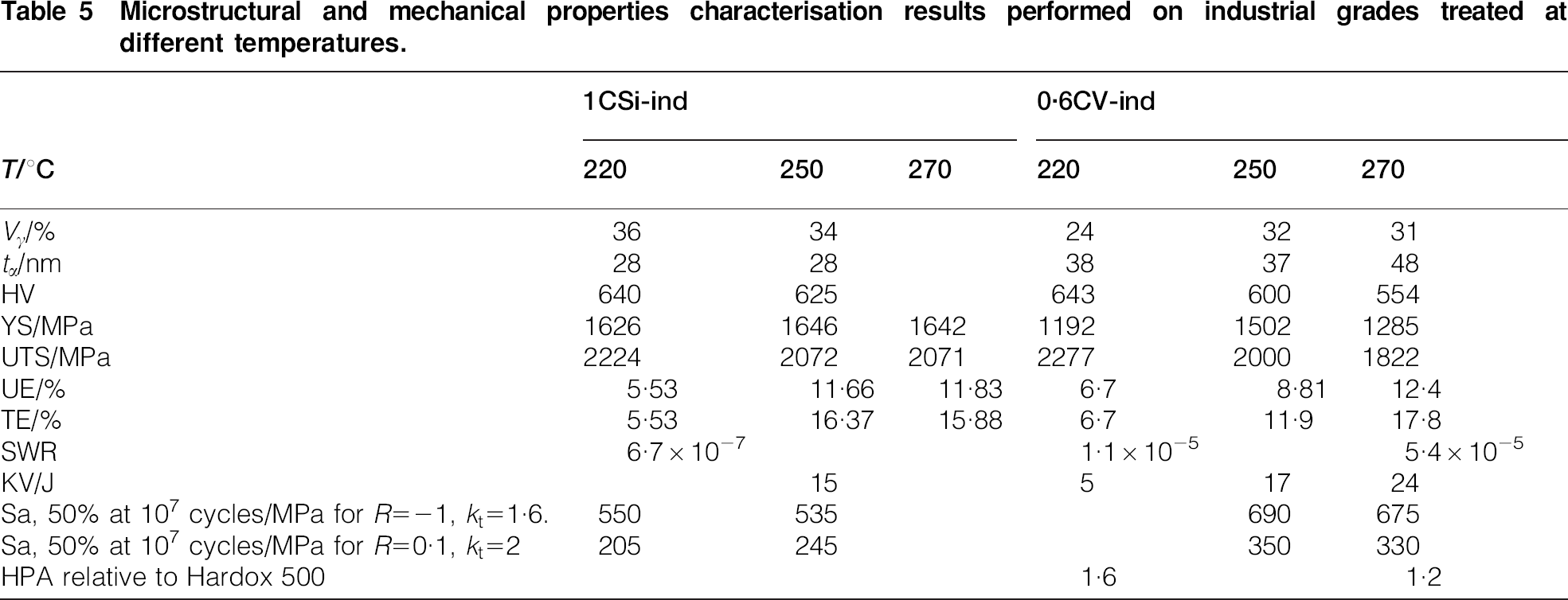
Results of rolling–sliding wear tests show that the results achieved on industrial material (1CSi-ind and 0·6CV-ind) represent a significant improvement when compared with similar laboratory casts of the same grades. It is also worth underlining that SWR on 1CSi-ind−220°C or 0·6CV-ind−220°C were about 1 or less of that measured of 100Cr6 bainitised to similar hardness, Table 5 and Fig. 4. It is thought that the combination of significant amounts of retained austenite (typically 30 in the tested conditions) and improved cleanliness led to those results. This may be explained if one considers the damage mechanism at hand. Examinations of tested specimens are consistent with damage mainly occurring through a rolling contact fatigue mechanism. It is well establish that cleanliness is an important factor in controlling the performance of high strength steels under rolling contact fatigue. Results clearly indicate that both oxides and sulphides content and sizes are significantly higher for the laboratory heat (as expected from measured S and O content and from manufacturing routes). It is thus not unlikely that the additional improvement achieved on industrial casts is related to improvement in cleanliness. It is therefore also remarkable that laboratory heats with relatively poor cleanliness performed significantly better than industrial 100Cr6 manufactured to bearing cleanliness standard. This suggests once again that retained austenite content and stability is a factor of primary importance in explaining the rolling/sliding wear performance of NANOBAIN grades.
Performances on rotation bending (kt = 1·6) were ultimately carried out on some of the industrial material (Table 5). In the case of 1CSi-ind, all of the failures had initiated on inclusions, which explains part of the observed scatter in the results. As expected, fatigue strength for the 0·6CV-ind is higher than in its higher C counterpart. The fatigue strength of both, 0·6C (laboratory heat) and 0·6CV (industrial heat), were found to be similar in spite of significant differences in cleanliness. This is in agreement with the absence of identified initiations on inclusions in these specimens.
Notched tension–tension fatigue tests (kt = 2) are representative of the functioning of heavily loaded car engine components (Table 5). Very similar results were obtained for the 0·6CV treated at 250 and 270°C, and detailed failure analysis indicated that there are two failure modes, crack initiation from the surface, <105 cycles at higher stresses, and crack initiation from non-metallic inclusion beneath the surface [Ti(C,N), >106 cycles at slightly lower stress], a division typical for high strength steels at that level of tensile strength.
Fatigue results for 1CSi industrial cast are not as readily interpreted as those for 0·6CV, Table 5. Fatigue results of the industrial cast 1CSi treated at 220°C exhibited high scatter in test data, and all samples were investigated using SEM. In addition to initiation sites, as already mentioned, some cracks were found to originate from corrosion pits. In addition, large cleavage fracture areas within the fatigue crack areas were found. Compared to the 220°C, experiments on samples treated at 250°C showed half of the scatter due to an increase of the ductility of the material by a factor of two. A division within two different failure modes can be seen, but this division is not as clear as in the case of 0·6CV-ind. For comparison purposes, a reference material for the manufacturing of the same car engine component, 100Cr6, has a fatigue strength of 355 MPa for the same testing conditions. 36 The results clearly show that, in spite of its significantly lower UTS than 100Cr6 (2350MPa), the 0·6CV-ind grade exhibited nearly identical performances. It must also be reminded that, with most failures initiated on Ti(C,N) in the 0·6CV grade, there is immediate potential for improvement since the concerned manufacturing plant routinely achieves Ti contents of 10 ppm and lower in bearing steels.
Additional high pressure abrasion and V-notched impact tests were carried out on 0·6CV-ind (Table 5) heat treated at different temperatures. The results, in line with previously obtained for lab grades (Fig. 5), raised a concern about toughness not being sufficient to allow safe operations, it was decided to heat treat the industrial components at 270°C.
Demonstrator and components
Finally, both alloys were used to manufacture component demonstrators or actual components that were tested in their representative conditions. The 0·6CV-ind alloy was used to manufacture a metal scrap shear of 524×80×200 mm3 dimensions. The heat treatment consisted of austenitising at 890°C and then isothermal heat treatment at 270°C for 7 h in salt bath. A full metallographic examination on different sections of the component (hardness, retained austenite and bainite lath thickness) revealed remarkably homogeneous results throughout the component, given its size, this results comes to demonstrate that transformation took place uniformly at the isothermal temperature, and not during cooling. Bainite lath thickness was measured at the centre and found to be 58 nm.
The standard material for this application normally provides 8000–12 000 cuts over their lifetime. The number of cuts achieved with the 0·6CV blade was lower though of similar order of magnitude. It was concluded that the observed reduction is partly due to changes in the feeding sequence, with very damaging rail steel having been introduced earlier than usual. Overall, it is felt that wear performance should undoubtedly be on par with the standard material once some fine tuning is carried out and for similar testing conditions. Despite the potential added cost due to the thermal treatment, gross benefit is estimated to be 10–20 due to the significantly cheaper material.
To evaluate the potential for industrial application in high loaded diesel injection systems, investigations using so called technological demonstrators were carried out, with both, the 0·6CV and 1CSi industrial grades, heat treated at 250°C. The specimens used for these tests have the same characteristic bore intersection as a rail body. Internal pulsating tests were carried out at a stress ratio R = 0·1. While results obtained on 1CSi were well below expectations, most likely due to the relatively poor cleanliness of the material, results obtained on 0·6CV were on par with those obtained on bainitised 100Cr6 in spite of the significantly lower UTS of the former. Because fatigue properties were difficult to correlate to microstructure, it is expected that further improvement can be made over this first set of results, once the contributing factors are better understood and quantified.
Conclusions
Over the course of the consortium, the nanostructured bainitic steel concept was taken from a laboratory experiment to full scale industrial production and component trials. A first achievement was to demonstrate that reasonable transformation kinetics could be achieved through tailoring of the alloy hardenability to its application. This was carried out without the use of sophisticated alloying elements such as Co, Ni or Al, leading to a reasonably inexpensive material. A second achievement was to demonstrate the superior potential of nanostructured bainite for abrasive wear applications and to confirm, through industrial trials, that the material was on par with significantly more expensive alloy steels.
In terms of fatigue performance of the nanostructured bainite, two very distinguishable behaviours have been reported, the 0·6C material, regardless of the manufacturing route, with fatigue strengths similar to that obtained with bainitic microstructure in 100Cr6. On the other hand, the results achieved on 1CSi were significantly lower and may partly be attributed to the poor cleanliness exhibited by the casts.
Finally, unprecedented ductility and strength levels during tensile tests were achieved on the NANOBAIN microstructure developed in the 1CSi material isothermally heat treated at ∼250°C, and such combination of properties is independent of the manufacturing route.
Footnotes
Acknowledgements
The authors gratefully acknowledge the support of the European Research Fund for Coal and Steel and the Spanish Ministerio de Economia y Competitividad Plan Nacional de I+D+I (2008–2011) for funding the present research under contract nos. RFSR-CT-2008-00022 and MAT2010-15330 respectively.