
Abstract
The discovery of iron based superconductors in early 2008 stimulated the interest of researchers around the globe, including physicists, chemists and materials scientists leading to publication of more than 4000 papers on this superconductor since then. Since the major player in the superconductor is iron, which had long been believed to be the worst element suited for the superconductivity, this discovery gave tremendous impact on the superconductivity research. Furthermore, this material has favourable characteristics for practical applications such as a relatively high critical temperature, high upper critical field and high critical current density with low anisotropy. In the last 3 years, many derived superconducting materials have been discovered and several theoretical models for the mechanism of superconductivity have been proposed. In this review, the research topics on iron based superconductors are summarised from the viewpoint of materials science.
Introduction
2011 marks the centennial of the discovery of superconductivity in Hg by Heike Kamerlingh Onnes. Prior to the report of cuprate superconductors by Müller and Bednorz1 in 1986, BCS theory seemed to fully explain superconductivity. However, Müller and Bednorz’s discovery resulted in a critical temperature (T c) above the liquid nitrogen temperature, (e.g. T c = 93 K of YBa2Cu3O7−δ ,2 T c = 105 K of Bi2Sr2Ca2Cu3O10 3 and T c = 134 K of HgBa2Ca2Cu3O8 4), and inevitably required a significant modification to the theory. Additionally, the finding of MgB2 (T c = 39 K) by Akimitsu’s group5 in 2001, which was basically explained by BCS theory, was another important step forward in high-temperature superconductors.
The iron based superconductor (LaFeAsO1−xFx: T c = 26 K) found by Hosono’s group6 in January 2008 rekindled global interest in this area and opened a new frontier for superconductivity. In the early stage, this superconductor family was called ‘Pnictide Superconductors’. However, researchers now call them ‘Iron based Superconductors’ (FeSCs) because several measurements and evaluations have clarified that they all have similar electronic structure where the 3d electrons derived from Fe ion play an important role in superconductivity. The appearance of iron chalcogenide affects also to call FeSC.
An electron is a complex particle which has electrical charge and spin. Magnetism emerges from the long-range ordering of electron spins, while superconductivity is generated based on the formation of Cooper pairs of electrons, which are mostly diamagnetic due to spin singlet state7 [Spin triplet pairs exist also in several materials as Sr2RuO4 (T c = 1·5 K),8 LiFeAs (T c = 18 K),9 PrOs4Sb12 (T c = 1·8 K),10 CePt3Si (T c = 0·75 K),11 etc., but such materials are exceptional]. Therefore, the relationship between magnetism and superconductivity had long been believed to be ambivalent, and the use of the elements leading to magnetism, typically Fe, Ni and Co, was intentionally avoided previously in the field of superconductivity. Hence, the discovery of a high T c superconductor based on iron significantly impacted research in this field. Material scientists and physicists encountered a new frontier of potential elements for superconducting materials and in the search of innovative properties and theoretical models.
Immediately after we reported an increase in T c (to 43 K) for La FeAs O0·89F0·11 under high pressure,12 two groups in China13 – 15 reported a high T c (55 K) for SmFeAsO1−xFx under an ambient pressure. By now, it is reported that the highest T c (55–56 K) in non-cuprate superconductors are observed for some FeSCs as SmFeAsO0·9F0·1,15 SmFeAsO0·85,16 SmFeAsO0·8H0·2,17 and Gd0·8Th0·2SmFeAsO.18
In July 2008, Johrendt’s group in Germany found (Ba,K)Fe2As2 (T c = 38 K).19 Thank to the ease of growing its single crystal which has a lateral size of several millimetres using Sn or FeAs as a flux, its material properties have been well investigated. Additionally, several types of FeSCs have been found, and researchers have identified their superconducting properties from various aspects.20 – 25
For more than a decade, our group has studied transparent conductors. Our study on transparent p-type semiconducting materials with high hole mobilities began with CuAlO2,26 and culminated in the discovery of LaCuChO (Ch: chalcogen).27 As a succession of this finding, we have focused on exploration for novel magnetic semiconductors by replacing Cu+ with magnetic elements such as Fe2+ or Mn2+. When we began this project, we did not anticipate the emergence of superconductivity, but fortunately we routinely measured the resistivity of our newly prepared materials down to 2 K. During these experiments, simultaneous substitution of Fe or Ni for Cu and P or As for Ch, led to discover of a few types of very low T c superconducting materials: [LaFePO (T c = 5 K),28 LaNiPO (T c = 3 K)29 and LaNiAsO (T c = 2·4 K)30]. T cs of these materials did not markedly increase even after impurity doping. Although non-doped LaFeAsO did not exhibit superconductivity, it displayed antiferromagnetism at a magnetic transition temperature (Néel temperature: T N) of 160 K, and changed into a superconductor (T c = 26 K) upon partial substituting O with F, i.e. electron doping. As noted above, this discovery led to the creation of the FeSCs field, which is currently a significant part of superconductivity research. In this review article, we overlook the accumulated knowledge of FeSCs mainly from the viewpoint of materials science.
Crystal structure of iron based superconductors
Although numerous FeSCs have been reported, their parent materials are classified into five types in terms of crystal structures (Fig. 1). These materials contains a common structural unit of the square net of Fe2+ (as formal charge) which is tetrahedrally coordinated by four pnictgen (Pn) or chalcogen (Ch) atoms (Fig. 1a ). Unlike cuprate superconductors, where the parent materials are Mott insulators, this layer shows a metallic conductivity without doping. An insulating blocking layer composed by M, MO or MF, etc. where M indicates a metallic element such as an alkali metal, alkaline earth or rare earth element that lies between FePn layers. Similar to cuprates, this layered structure provides quasi-two-dimensional carrier transport properties. The local structure of the FePn layer is affected directly by the atomic (or ionic) size of M because M elements in the blocking layer bond to Fe elements in the conducting layer. The five different parent materials for FeSCs are described below.
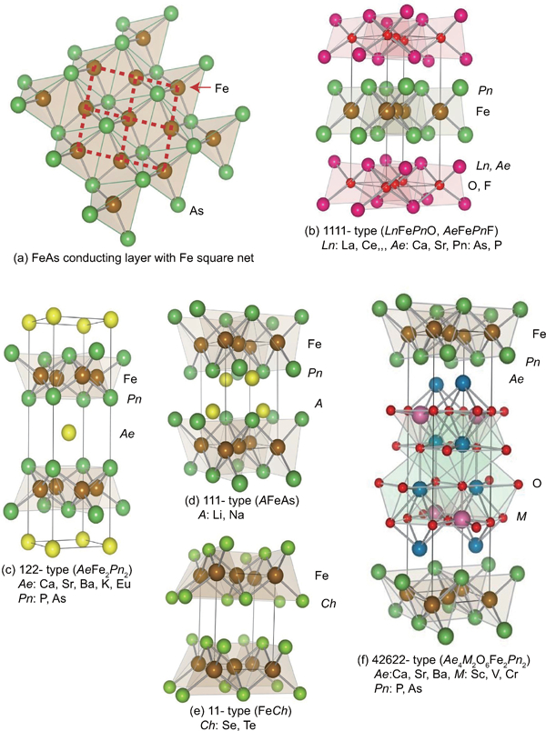
a Structure of the FeAs conducting layer, which is common to all FeSCs. Dotted line indicates the Fe square net. Crystal structures of FeSC family for b 1111-type, c 122-type, d 111-type, e 11-type and f 42622-type
1111-type materials (LnFePnO, Ln: lanthanide, AeFeAsF, Ae: alkaline earth, Pn: P, As)
1111-type comprises compounds with the same structure as LaFeAsO, and is the earliest versions of FeSCs. Due to their atoms composition ratios, they are called the ‘1111-type’. Figure 1b show their crystal structure, which is a ZrCuSiAs type structure31 with a tetragonal P4/nmm space group. Over 300 materials belong to this group, including the p-type semiconducting LaCuChO (Ch = S, Se, Te) with the wide band gap mentioned in the introduction. Although LaFePO and LaFeAsO along with their crystal structures were identified 10 years ago, they were discovered to be superconductors in 200628 and 2008,6 respectively. Moreover, their two-dimensionality is relatively high among the five types, and only this group has T c values above 50 K.
The unit cell of 1111-type compounds (a∼0·4 nm, c∼0·8–0·9 nm) contains two atoms of each component, and is composed of an alternating stack of positively charged LnO layers and negatively charged FeAs layers along the c-axis. The FeAs layer is constructed with an array of share edged FeAs4 tetrahedrons, which constitute the planar square net of Fe. As mentioned above, the local structure of the FeAs layer is the same in all types of FeSCs. The distance between the FeAs layers corresponds to the length of the c-axis (∼0·8–0·9 nm). The formal valence state of each atom is Ln 3+, Fe2+, As3− and O2−. A Fe2+ contains six electrons in its 3d orbital, and these electrons play an essential role in driving the superconductivity and magnetism. The lanthanide elements from La to Gd can occupy the Ln site for a 1111-type of material with Pn = P.32 In the case of Pn = As, La to Ho and Y can also occupy the Ln site.33 Additionally, Ca(Fe1−xCox)AsF (T c = 22 K) is a fluoride containing superconductor of this type.34
122-type materials [AeFe2Pn2, Ae: alkaline earth (alkali metal, Eu)]
122-type materials have a ‘ThCr2Si2’ crystal structure with a tetragonal I4/mmm space group.35 This group contains the most abundant compounds among the 5 parent families. CeCu2Si2, a typical heavy fermion, belongs to this group as well.
In the case of AeFe2P2, not only alkaline earth elements but also lanthanides (La-Pr, Eu) can occupy the Ae site. In AeFe2As2, the Ae site can be occupied by alkaline earth, alkali metal or Eu2+. Figure 1c shows the crystal structure for the 122-type. The layer composed by Ae ions, which is thinner than the Ln–O layer of the 1111-type, is sandwiched by the FeAs conducting layers. The distance between the FeAs layers of the 122-type (0·5–0·6 nm) is shorter than that of the 1111-type (0·8–0·9 nm). Because the nearest FeAs layers face each other with a mirror plane, the lattice parameter c is twice the FeAs–FeAs distance. The lattice parameter a (∼0·4 nm) is almost the same as that of the 1111-type. Consequently, both 1111- and 122-type materials have similar Fe–Fe distance in the FeAs layer. Since relatively large single crystals of several millimetres can be obtained using Sn or FeAs as a flux, the physical properties of 122-type are well evaluated relative to other types of FeSCs. Johrendt’s group of Germany was the first to report superconductivity for 122-type materials.19
In 2010, Guo et al. reported a potassium-intercalated iron selenide superconductor with relatively high T c value (30 K for KxFe2Se2).36 Crystal structure changed from 11-type to 122-type upon intercalation. Though its crystal structure is similar to that of the 122-type, the space group is assigned to I4/m due to vacancy ordering. The detail is noted in the section on ‘Non-stoichiometric 245-type materials (A2Fe4Se5, A: K, Rb, Cs, Tl)’.
111-type materials (AFePn, A: alkali metal)
While Ae ion (alkaline earth ion with formal charge of 2+) is sandwiched by FePn layers alternately in the 122-type, 111-type compounds contain two A ions (A: Li+, Na+) between FePn layers in an unit cell. The crystal structure of this type is known as the ‘CeFeSi’ type, with a tetragonal P4/nmm space group (Fig. 1d ). This type is compatible with the structure of the 1111-type where all the oxygen atoms are removed, and the Ln site is occupied by Li+ or Na+. Wang et al. 37 (T c = 18 K: LiFeAs) and Parker et al. 38 (T c = 18 K: NaFeAs) first reported superconductivity for 111-type materials.
11-type materials (Fe1+xCh, Ch: Se, Te)
The 11-type crystal structure is simplest among the parent compounds and is essentially the 111-type without alkali metals. This crystal structure is known as ‘α-PbO’ type with a tetragonal P4/nmm space group (Fig. 1e ). A typical 11-type superconductor is β-FeSe (T c = 8 K).39 From the phase diagram of Fe–Se, the β-type exists in a narrow composition region (x = 0·010–0·025 in Fe1+xSe) and the stable crystal structure at room temperature of the NiAs structure type is α-FeSe with a hexagonal lattice. To obtain β-FeSe, the material is kept at 400°C for a long period of time. Medvedov et al. have suggested the 11-type may exhibit a high T c ( = 37 K) under 8·9 GPa.40 Mizuguchi and Takano review this material.41
Materials with thick blocking layer
[32522-type (Ae3M2O5Fe2Pn2, M: Al, Sc)]
[42622-type (Ae4M2O6Fe2 Pn 2, M: Sc, V, Cr)]
[homologous type (Can+1ScnOyFe2As2: n = 3, 4, 5)]
The distance between the FePn/Ch layers shortens in the order of the 1111-, 122-, 111- and 11-types. In contrast, these three types of iron oxy-pnictide have a thick blocking layer composed of a quasi-Perovskite structure assembled by MO5 pyramids and Ae [see Fig. 1f for the 42622-type (Sr4Sc2O6Fe2As2)]. The FeAs–FeAs distance is 1·55 and 2·45 nm for Sr4Sc2O6Fe2As2 and Ca6(Sc0·4Ti0·6)5OyFe2As2 respectively. Ogino et al.’s group has studied this type of materials systematically.42 – 44 The highest Tc reported so far is 43 K for Ca6(Sc,Ti)5OyFe2As2.44 Considering the thick blocking layer, this type should have the highest two-dimensionality, but the concrete value of anisotropic properties has not been reported yet. The 32522-type has been proposed as a promised parent material,45, 46 and the emergence of superconductivity in the 32522-type is reported by Shirage et al. at 2011 for (Ca3Al2O5−y)(Fe2Pn2) [Pn = As (T c = 30·2 K) and P (T c = 16·8 K)].47
Parent material and superconductivity
Doping effect
The parent materials, LnFeAsO and AeFe2As2, do not exhibit superconductivity, and become superconductors with high T c only by partial substitution for other elements. In this section, the doping effect is discussed with a focus on the 1111- and 122-types. Typical examples of emergence by doping are listed in Table 1.
Typical example of emergence of superconductivity by doping (T c and composition)
Doping of the 1111-type
The parent materials for the 1111-type have tetragonal crystal structure at room temperature, but transform into orthorhombic structure at lower temperatures. In LaFeAsO, Pauli paramagnetism is shown at room temperature, and changes into antiferromagnetism at a slightly lower temperatures (T N∼140 K) than that of the structural transitions (T s∼160 K).48, 49 The change in lattice constants with temperature for LaFeAsO1−xFx is shown in Fig. 2.48 The lattice constant a of tetragonal phase of the undoped material bifurcates to a and b of orthorhombic phase at 165 K with decreasing temperature, whereas the doped material (x = 0·14, showing superconductivity below 20 K) does not show such a bifurcation.
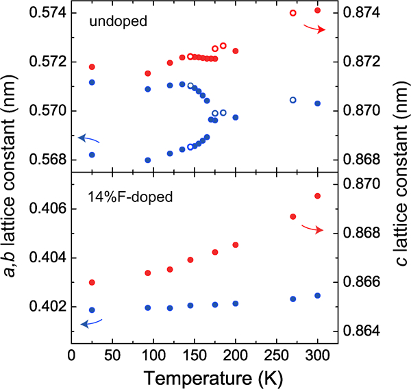
Crystallographic transition in LaFeAsO. a-, b- and c-axis lengths of undoped and 14% F-doped LaFeAsO are shown as a function of T. The axes of the undoped LaFeAsO are defined as the orthorhombic phase, and those in the 14% F-doped LaFeAsO are as the tetragonal phase. Closed and open circles are obtained in the heating process and the cooling process respectively. Reprinted from Ref. 48
The magnetic structure of parent material, CaFeAsF (antiferromagnetic metal phase), measured by neutron diffraction at low temperature is shown in Fig. 3.20, 50, 51 The Fe moments are parallel to the longer b axis. Spins are aligned ferromagnetically along the shorter a axis and antiferromagnetically along b and c axes, i.e. a stripe structure. Since spin array on the FeAs layer piles up inversely, the cell parameter for magnetic lattice c M is twice of that for crystal lattice c.
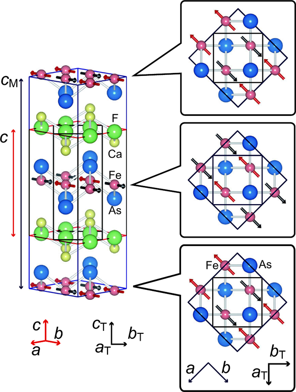
Crystal and magnetic structure of CaFeAsF. Crystal structure is tetragonal at room temperature (lattice parameters a T = b T∼0·4 nm, c T∼0·9 nm), but transforms into orthorhombic (lattice parameters a>b∼(2a T)1/2, c∼c T) at 120 K. In the antiferromagnetic phase (<118 K), the electron spins of Fe order parallel to the b-axis and opposite to the a-axis direction, aligning the total moment in the a-axis direction. Because spins order with inversion between neighboring FaAs planes, the c-axis length of the magnetic sublattice is twice of that of the crystal lattice. Reprinted from Ref. 20
Generally, the superconductivity occurs in the tetragonal phase and not in the orthorhombic phase due presumably to antiferromagnetic ordering in the orthorhombic phase. With doping (e.g. substituting O for F in LnFeAsO), the tetragonal–orthorhombic transition temperature decreases and is accompanied by the suppression of the antiferromagnetic state and superconductivity emerges in succession. Electrons are doped into the bulk, when an element with more valence electrons is substituted. In contrast, holes are doped by substituting an element with fewer valence electrons. In many cases of both 1111- and 122-types, it is possible to substitute Fe or As in the conducting layer and Ln, Ae, O or F in the blocking layer for other elements. The former and latter are called ‘direct doping’ and ‘indirect doping’ respectively.
The critical temperature (T c) increases, reaches a maximum, and then decreases as the dopant levels increases. Since the decrease in T c in the over doping level is due to the precipitation of the secondary phase as SmOF in SmFeAsO1−xFx, the proposed phase diagram for 1111-type doped with F does not show the T c behaviour in the over doping region.52 – 56 In contrast, Hanna et al. 17 prepared SmFeAsO1−xHx and showed its optimal T c (55 K) at x = 0·20 and decrease in T c by additional doping (over doping) without precipitation of secondary phase, indicating a wide superconducting dome in 1111-type. Figure 4a shows the schematic phase diagram for the 1111-type.
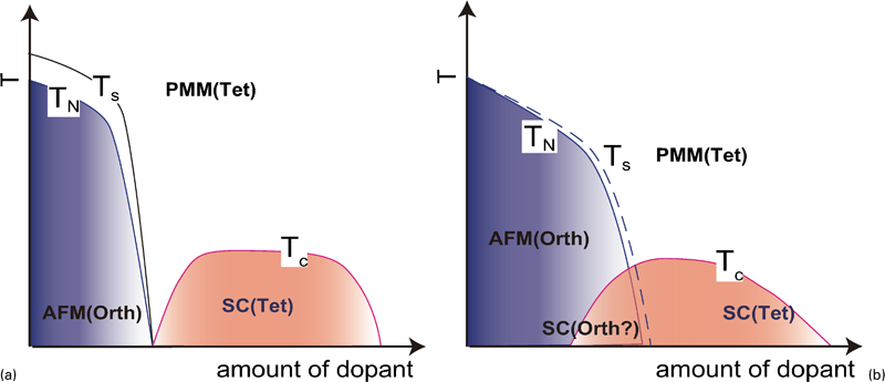
Schematic temperature versus composition phase diagram for a 1111-type and b 122-type (T s: structural transition temperature; T N: magnetic transition temperature; AFM: antiferromagnetic phase; PMM: paramagnetic metal phase; SC: superconducting phase)
The 1111-type contains at least four components (more than five if dopants are included), and precisely controlling its composition is very difficult. Even if starting materials are mixed at the correct composition ratio, the prepared substance contains a spurious phase whose composition differs from the nominal one for many polycrystalline materials. For example, the spurious phases of SmOF, SmAs and/or Sm2O3 are formed, and their concentrations increase as the dopant concentration increases in SmFeAsO1−xFx, which shows the highest T c in FeSC family.14,54 – 58 This situation is similar to those of other 1111-type materials containing rare earth elements. The spurious phase, LnOF, is very stable, and consequently, difficult to erase. Malavasi et al. 52 demonstrated the difference in composition between nominal and prepared NdFeAsO1−xFx from quantitative analysis using an electron probe microanalysis; they noted that the measured F content in a specimen with the nominal composition of NdFeAsO0·78F0·22 is 0·188. The relationship between the nominal F content and the real one determined by means of electron probe microanalysis is shown in Fig. 5. Karpinski et al. reported that without exception, single crystals of LnFeAsO1−xFx (Ln = La, Pr, Nd, Sm, Gd) contain considerable oxygen deficiencies.59
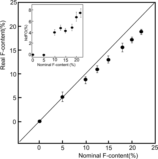
Plot of the nominal F content of prepared polycrystalline NdFeAsO1−xFx against the real F content determined by EMPA. Inset: amount of NdOF phase as a function of the nominal F-content. Reprinted from Ref. 52
The first FeSC reported was formed by electron doping as LaFeAsO1−xFx where F occupied the O site as (FO •+e’).6 Adding to the substitution of F (T c = 55 K for SmFeAsO0·9F0·1),15 various procedures for the electron doping have been reported, including the formation of an oxygen vacancy (VO+e′: T c = 55 K for SmFeAsO0·85) using a high-pressure synthesis,16, 60, 61 substitution of H− for an O2− site (HO •+e′: T c = 55 K for SmFeAsO0·8H0·2),17 substitution of Th for Ln (ThLn+e′: T c = 56 K for Gd0·8Th0·2FeAsO),18, 62 and substitution of Co, Ni or Ir for Fe (CoFe •+e′: T c = 14 K for LaFe1−xCoxAsO,63, 64 T c = 22 K for CaFe1−xCoxAsF,34 NiFe ••+2e′: T c = 6 K for LaFe1−xNixAsO,65 IrFe •+e’: T c = 18 K for SmFe1−xIrxAsO66). The optimal amount of doping is 0·1–0·2/Fe atom for each operation, and indirect doping appears to be more effective than direct doping in achieving a high T c, which should be due to less distortion of the conducting layer. Figure 6a and b show the ρ–T plots of undoped LnFeAsO (parent) and oxygen vacancy doped LnFeAsO (superconductor), respectively.67 The change in slope at 100–150 K shown in the parent material (Fig. 6a ) indicates structural and magnetic phase transitions. Doping suppressed these transitions and superconductivity emerges. In both of F and oxygen deficiency doping shown in Fig. 7, a high T c (>50 K) is observed for Ln = Pr, Nd, Sm, Gd and Dy in Ln-1111. Though it was noted that the low T c of Eu-1111 was attributed to the large atomic radius of Eu,74 the effect of the change in the formal valence of Eu (+3→+2) should be considered.
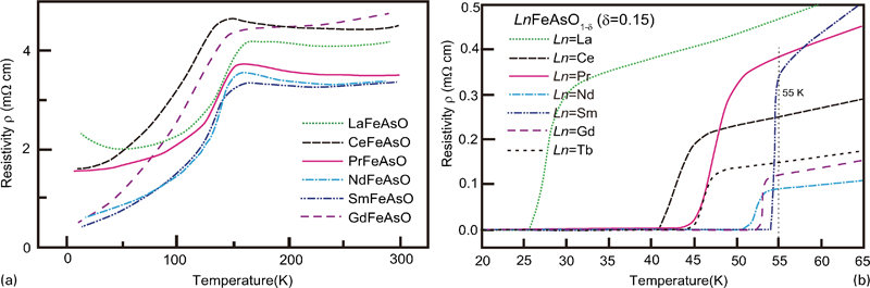
Temperature dependence of resistivity for some typical 1111-type a parent materials (LnFeAsO) and b oxygen deficient superconductors (LnFeAsO1−y). Reprinted from Ref. 67
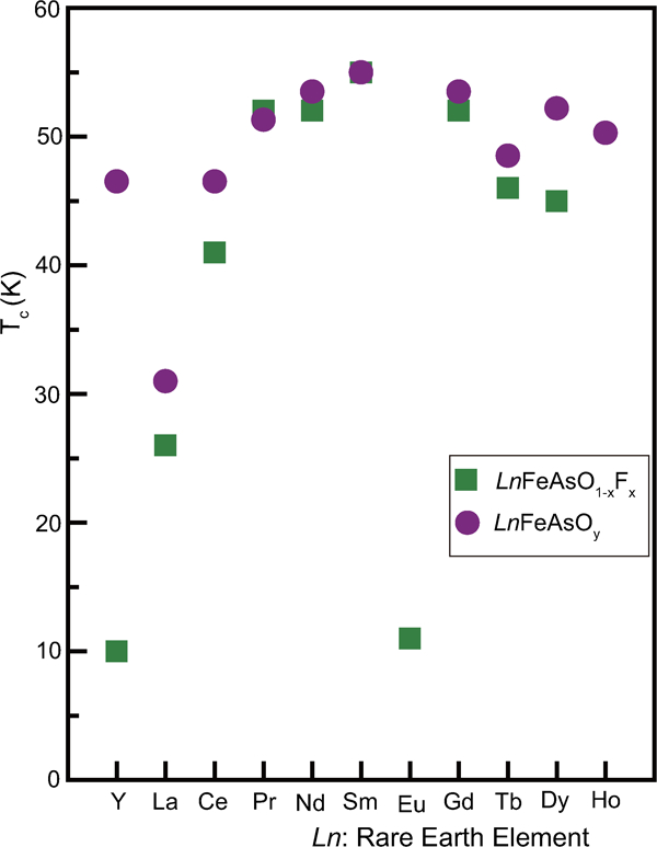
Maximum T cs reported for Ln-1111 superconductors prepared by doping with F (LnFeAsO1−xFx, green square) and oxygen deficiency (LnFeAsO1-y, violet circle) (data from Refs. 6, 14–16, 61, 68–74)
Using hole doping, superconductivity emerges by substituting Ln for Sr (Nd1−xSrxFeAsO, T c = 13·5 K at x = 0·2), but its diamagnetic shielding volume fraction remains 17% at x = 0·2.75, 76 Additionally, it is not easily understand that each compound examined here including superconducting compound (x = 0·2) shows the structural transition from the tetragonal to the orthorhombic phase at ∼130 K as the temperature decreases, and hence the superconducting state appears in the orthorhombic phase.76 Further effort appears to be needed to clarify the effectiveness of hole doping in 1111-type.
The substitution of isoelectronic element as Ru for Fe or P for As do not lead the emergence of superconductivity in 1111-type. When Ru is substituted for the Fe sites in PrFeAsO, the formations of spin density wave is suppressed, but the superconductivity does not emerge.77 In case of Ru substitution into superconducting phase as NdFeAsO0·89F0·11 78 or SmFeAs0·85F0·15,79 its T c decreases with increasing in the Ru content. The substitution of P for As results in similar mannar.80
Doping into the 122-type
Compared to the induction of the superconductivity in the 1111-type, doping methods to generate 122-type superconductors are more diverse. Ba1−xKxFe2As2 (T c = 38 K at x = 0·4), which utilises the indirect hole doping, has the highest T c.19 Sr1−xLaxFe2As2 prepared using a high-pressure technique utilises the indirect electron doping (T c = 22 K at x = 0·4),81 and typical direct electron doping is realised in Ba(Fe1-xCox) 2As2 (T c = 23 K at x = 0·2)82 and some transition metal dopings.83 – 85 Similar to that for 1111-type materials, the optimal carrier concentration is 0·1–0·2/Fe atom for both electron and hole doping cases, which differs from the 1111-type. Figure 8 shows T c and T s for BaFe2As2 with direct electron doping by substituting transition metals for Fe sites.86
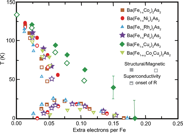
T–e phase diagram of BaFe2As2 with Co, Rh, Ni, Pd, Cu and Cu/Co doping. The abscissa indicates extra electrons per Fe. Reprinted from Ref. 86
Another feature of the 122-type is the emergence of superconductivity by substituting isoelectronic elements such as Ru (for Fe)87 or P (for As).88 As mentioned in the section on ‘Doping of the 1111-type’, such substitution for the 1111-type does not lead the emergence of superconductivity. However, the superconducting state is induced by replacing As sites with P in BaFe2(As0·68P0·32)2 (T c = 30 K) and by substituting Ru for Fe sites in Ba(Fe0·56Ru0·44)2As2, (T c = 22 K). Due to a decrease in lattice parameter upon the isoelectronic element replacement of P with As, the induction of superconductivity was initially explained as a chemical pressure effect. However, this explanation is not applicable to the case of Ba(Fe1−xRux)2As2, where the lattice parameter increases upon replacement. Brouet et al. 89 investigated Ba(Fe0·65Ru0·35)2As2 by transport measurement and angle resolved photoemission spectroscopy and deduced a twofold increase in the area of the Fermi surface pocket compared to BaFe2As2, which means doubling of carrier concentration of both electrons and holes, and significantly enhances the Fermi velocity. They suggested that Ru substitution weakens the electron correlation through the covalent bonding effect of Ru compared to Fe. Furthermore, the de Haas–van Alphen effect measurement on a P substituted sample revealed a smaller effective mass and larger Fermi surface.90 However, it has not been clarified yet whether such doping does not enhances the superconductivity in 1111-type materials.
Unlike cuprate superconductors whose parent materials are Mott insulators, the parent materials of FeSCs are antiferromagnetic metals with sufficient conduction carriers. Hence, it is considered that doping into FeSCs mainly affects the band structure and/or suppresses antiferromagnetism instead of controlling the carrier density when doping level is not so high.
The phase diagram of 122-type is schematically shown in Fig. 4b . Like 1111-type, the structural transition temperature of tetragonal–orthorhombic decreases accompanying with the suppression of the antiferromagnetic state and superconductivity emerges in succession with increasing in substituent.19,81 – 86,91 The remarkable difference between the 1111- and the 122-type is overlapping of antiferromagnetic and superconducting phases. In the 1111-type, the regions showing antiferromagnetism and superconductivity are separated or barely overlap, whereas the 122-type materials have antiferromagnetic regions with a high T c. The optimal T c is apparently located around the temperature corresponding to the extrapolation of SDW curve to zero temperature, i.e. superconducting dome appears around the quantum critical temperature of SDW. The overlapping extent in CaFe1−xCoxAsF is intermediate between the 1111- and the 122-type.92
Non-stoichiometric 245-type materials (A2Fe4Se5, A: K, Rb, Cs, Tl)
This type is the latest FeSC family member with relatively high T c value. Although this material type was initially classified as the 11-type intercalated by alkali metal or the 122-type, it is called the 245-type from the viewpoint of its accurate parent composition. Guo et al. first reported that KxFe2Se2 (nominal composition) showed relatively high T c (30 K).36 The detailed chemical and structural analyses for its optimal material showed the composition to be A0·8Fe1·6Se2 ( = A2Fe4Se5) and ordering of Fe vacancies with 51/2×51/2×1 supercell in the 122-type crystal structure.93 Figure 9 shows the supercell structure of K0·774Fe1·613Se2 from the [001] direction. This type of materials shows a wide range of non-stoichiometry and that with low Fe concentration is an antiferromagnetic insulator. In (Tl,K)FeySe2 (Fig. 10), the material in the region of y<1·68 is an antiferromagnetic insulator, its Néel temperature T N decreases with increasing in y, and the superconductivity emerges at y>1·7.94 The superconductivity in AxFeySe2 emerges in the proximity of an AFM Mott insulating state, similar to the cuprate high temperature superconductors. The band structure calculations95, 96 and preliminary angle resolved photo-emission spectroscopy measurements97, 98 indicate that the band near the Γ-point seems to dive below the Fermi energy, leading to the absence of hole pockets, which are prerequisites for the pairing model mentioned in the sections on ‘Growth of the 122-type single crystals’ and ‘Growth of the 1111-type single crystals’. This discrepancy with the model previously accepted for FeSCs has received attention from physicists attempting to understand the pairing mechanism as well as those exploring materials. Such unique properties let us to classify this as an independent type apart from the 122-type. Ivanovskii reviews this type (where he describes this type as 122-like iron selenide system.).99
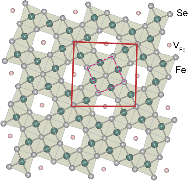
The proposed superstructure of K0·775Fe1·613Se2 from the [001] direction in the (51/2×51/2×1) cell showing fully occupied Fe sites decorated with ordered vacancy sites. Dotted square indicates the basal plane of 122-type unit cell. Reprinted and modified from Ref. 93

Phase diagram of the magnetism and superconductivity for (Tl,K)FexSe2 (1·30⩽x⩽2·0). The Néel temperature T
N of the AFM phase is determined by the onset temperature of the transition in χ(T). The SC transition temperature
Local structure and superconductivity
Several models to explain the relationship between the structure and superconducting properties have been reported from the earlier stage of FeSC research. The first endorsed model proposed by Lee et al. is a method to classify T c by the angle (α) of As–Fe–As in the FeAs layer.100 As shown in Fig. 11, the highest T c in the oxide 1111-type series (LnFePnO) is observed in materials with α corresponding to a regular tetrahedron (109·47°) such as Gd-, Sm- and Nd-1111. In this figure, the highest T cs reported and the α values mainly for the parent materials at room temperature are plotted. These data suggest the shape of the FeAs4 tetrahedron may predict T c. Although the regular tetrahedron rule has been endorsed empirically, its physical meaning has yet to be clarified. Intuitively, we can imagine an increase in the density of state on the Fermi surface by the degeneracy of the orbitals resulting from the high symmetry around the Fe atom. This model has been successfully applied to fluoride 1111-type (AeFeAsF), by comparing CaFeAsF (α = 108°, T c = 22 K) and SrFeAsF (α = 112°, T c = 7 K) where Co is doped into both parent materials to introduce superconductivity.34 The regular tetrahedron rule can be also applied to the 122-type; one material (AeFe2As2) with an α value close to 109·47° shows a high T c (e.g. Ba1−xKxFe2As2 shows the highest T c at x = 0·3–0·45). According to the structural analysis of BaFe2As2 under high pressure by Kimber et al.,101 where superconductivity (T c = 31 K) emerges under the pressure of 5·5 GPa, the changes in the structure in terms of lattice parameters and As–Fe–As bond angle are similar to those by the chemical doping with K. They emphasised that a structural change due to the chemical pressure effect is more important to drive superconductivity than charge doping. To establish the generality of such a relationship, more experimental are obviously needed to reach the conclusion.
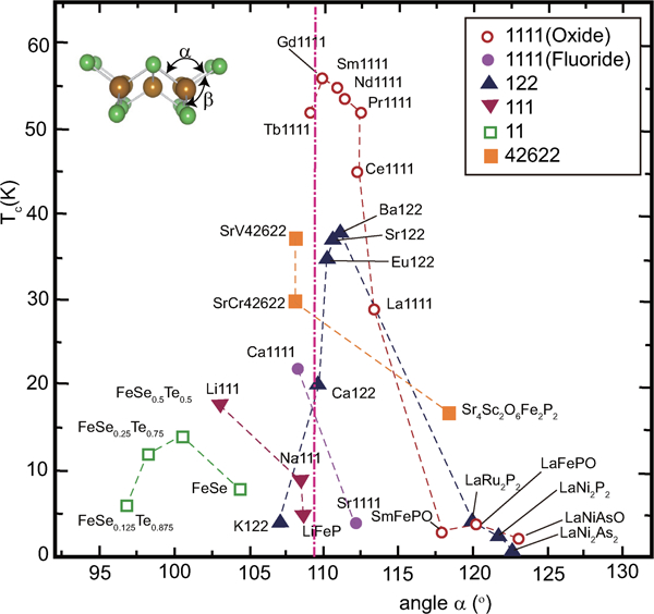
Correlation between T c and bonding angle α of Pn(Ch)–Fe–Pn(Ch). α is adopted mainly from the data of the parent materials measured at room temperature. T c shows the highest reported value. Reprinted from Ref. 20
Kuroki et al. proposed a theoretical model to explain the relationship between the structure and T c on the basis that spin fluctuation is the dominant mechanism.102 They extracted an important parameter h Pn, which indicates the height of the pnictogen atom measured from the Fe plane; then they calculated the changes in the electronic structure and magnetic properties with changes in h Pn. Their calculations indicate the appearance of the Fermi surface γ around (π,π) in the unfolded Brillouin zone is sensitive to h Pn and this Fermi surface controls the strength of the nesting effect, T c, and the symmetry of the superconducting gap. They concluded that T c increases with increases in h Pn. Figure 12 plots this relationship where T cs and h Pns are employed in same manner as in Fig. 11. In Fig. 11, materials showing high T cs are roughly localised around α = 109·5° for the 1111-, 122- and thick blocking layer types, but the deviation from the regular tetrahedron rule is found in the 111-type where LiFeAs (α∼103°) shows a higher T c (∼18 K) than NaFeAs (T c∼9 K, α∼108·5°) or LiFeP (T c∼6 K, α∼108·5°). Although rules cannot be deduced from the h Pn-T c relationship in Fig. 12, a positive correlation for each material type is observed and the discrepancy for the 111-type in Fig. 11 is at least resolved. However, several discrepancies remain. h Pn of KFe2As2 is highest in superconductors belonging to the 122-type, but its T c is low (∼4 K).103 For the 11-type, h Pn increases with the Te content, but the T c shows a maximum at x = 0·5 in FeSe1−xTex.104
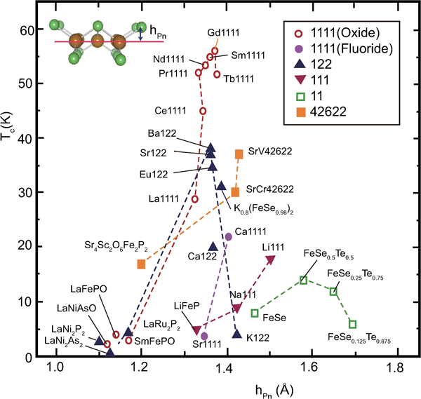
Correlation between T c and Pn(Ch) height from the Fe plane h Pn. h Pn is adopted mainly from the data of the parent materials measured at room temperature. T c shows the highest reported value. Reprinted from Ref. 20
Here we would like to discuss models for each type. Figure 13 shows the relationship between h Pn and T c for the doped Ln-1111-type superconductor.22, 58 The closed and open marks indicate F doped (LnFeAsO1−xFx) and O vacancy doped (LnFeAsO1−y) samples respectively, and dotted lines denote the h Pns of the parent materials. Except for two points of Pr-111122, 105 on left-upper side where h Pns were measured at low temperature (5 K), a positive correlation is roughly shown, suggesting the h Pn–T c rule is applicable to the real superconductors. However, it is impossible to apply this rule to an individual doping operation where h Pn changes monotonically as the amount of dopant increases and the highest T c emerges at the optimal composition due to such doping. For example, (Ba1−xKx)Fe2As2 is a complete solid solution system106 where hPn of BaFe2As2 (1·358 Å) increase monotonically with an increase in x toward that of KFe2As2 (1·429 Å) and the highest T c emerges at x = 0·37, h Pn = 1·383 Å (Fig. 14). The regular tetrahedron rule is effective to explain the trend in this material series. Empirically, the maximum T c is shown at h Pn∼1·25–1·4 Å for 1111 and 122-types.

Correlation between h
Pn and T
c for 1111-type superconductors of LnFeAsO1−xFx (closed marks) and LnFeAsO1−y (open marks): (La:


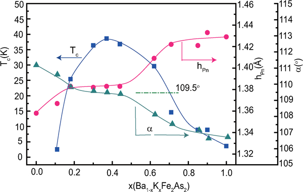
T c, h Pn and α for Ba1−xKxFe2As2 (data from Ref. 106)
Regardless of the high correlation between each structural parameter and T c (α–T c, h Pn–T c), several deviations remain. Consequently, a structural parameter that is applicable to FeSCs as a whole has yet to be found. On the other hand, the unique characteristics of each type of FeSC have been determined as FeSC research has progressed. Hence, it is unclear whether a universal parameter to describe the characteristics of FeSCs as a whole exists.
Ogino et al. systematically prepared FeSCs with different blocking layer thicknesses as 42622- and homologous-types to evaluate the relationship between this thickness and T c.42 – 44 As shown in Fig. 15, a remarkable change in T c is not observed with a change in the thickness up to 25 Å.44
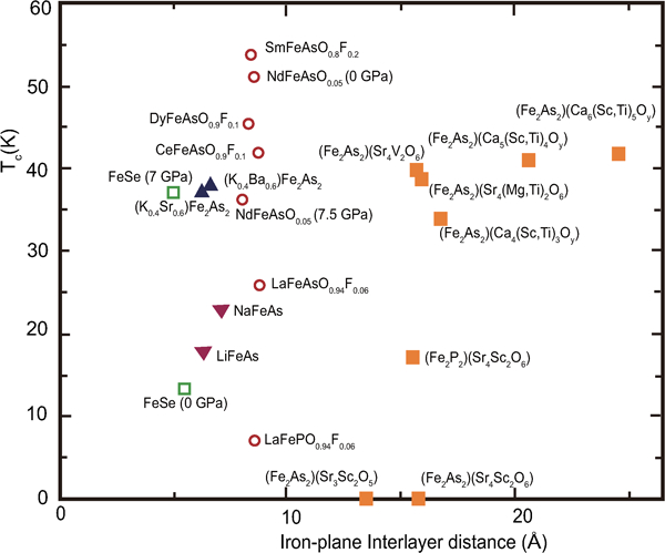
Correlation between T c and iron plane interlayer distance for various layered FeSCs. Reprinted from Ref. 44
Unique characteristics of FeSCs
Compared to the other high T c superconductors of MgB2 and cuprates, FeSCs have several distinct characteristics.
Multiband nature of Fe 3d
Figure 16 shows the photoemission spectra for LaFeAsO and LaFeAsO0·94F0·06, and calculated PDOS for Fe 3d and As 4p.107 The electronic state of the Fermi level (E
F) controlling the transport property is formed by a complex tangle of five Fe 3d orbitals, due to the small contribution of As, which is unlike cuprate superconductors where only Cu 


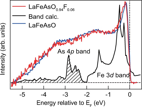
Photoemission spectra of LaFeAsO1−xFx and calculated PDOS. The near-E F peak and the weak peak at about −1·5 eV corresponding to Fe 3d bands survive, and a broad peak corresponding to the As 3p band appears in the range –(3–4) eV. Reprinted from Ref. 107
Parent material: antiferromagnetic metal
Metal compound superconductors such as MgB2 do not exhibit magnetism and their conduction electrons induce superconductivity without doping. The parent materials of cuprate superconductors are antiferromagnetic insulators with a moment of ≈1 μB/Cu, which corresponds to nine electrons localised in the 3d orbital. The parent materials of the 1111- or 122-type FeSCs are antiferromagnetic metals, and their magnetic moment per Fe atom is 0·4–0·9 μB which is much smaller than that due to the six electrons localised on Fe2+ with a high spin state (4 μB). The repulsive energy, i.e. on site Coulombic energy, between 3d electrons in FeSC is approximately half that in cuprate. These results demonstrate the strong itinerant nature of electrons in FeSCs.
The antiferromagnetic spin fluctuation and the multiband effect discussed in the above section are two factors to drive the system into the superconducting state. The pairing is established via interpocket scattering of electrons between the hole pockets (around the Γ point) and electron pockets (around the M point), and lead to a pairing situation where an isotropic gap with opposite signs on each pocket (so called S± symmetry). The form of the superconducting gap is an exciting topic in the theory of superconductivity (see references cited in the section on ‘Multiband nature of Fe 3d). Very robust behaviour to impurity, which has found recently, suggests non-sign-reversal mechanism, i.e. S++, would be more plausible.78,111 – 115
Effect of transition metal substitution for Fe on T c
Generally, T cs of superconductors decrease upon doping with magnetic impurities such as Fe, Ni and Co. In case of cuprate superconductors, T c of YBa2Cu3O7−y decreases from 90 to 50 K by substituting Ni (17%) for Cu, and that of La1·85Sr0·15CuO4−y also decreases from 40 to 4·2 K by substituting Ni (5%) for Cu.116 The substitution of such elements for Fe on FeSCs with optimal state shows a similar trend. The superconductivity of NdFeAsO0·89F0·11 (T c = 48 K) disappears by substituting Co (>11%) or Mn (>4%).117 Interestingly, Mn substitution which strongly depresses the superconductivity in most of cases, hardly affects the T c value of K0·8Fe2−x−yMnxSe2, where T c for x = 0 (30·5 K) falls by only 2–3 K up to x = 0·067, whereas the superconductivity of K0·8Fe2−x−yCoxSe2 vanishes by doping of small amount of Co substitution (x = 0·018).118
In contrast, the emergence of superconductivity by substitution of Co2+ (3d 7), Ni2+ (3d 8) or other transition metals for Fe2+ (3d 6) in the non-superconducting parent material is a unique nature for FeSC,34,63 – 66,82–87 similar to the result of electron doping into the FeAs layer as described in the section on ‘Doping effect’. The substituent with transition metal to induce superconductivity is restricted to the groups 9 (Co, Rh, Ir) and 10 (Ni, Pd, Pt) of the periodic table (Ru is effective in the 122-type.), while the substitution of Mn or Cu does not lead the emergence of superconductivity.83, 119 Substitution for a transition metal with a large site Coulombic energy appears to work as an effective scattering centre.
Large critical field and small anisotropy
The superconducting performance is characterised by the critical temperature (T c), critical current density (J c), upper critical field (H c2) and anisotropy. Table 2 summarises these values of FeSCs alomg with those of MgB2 and cuprates. Only cuptrates achieve the higher T c than the boiling point of liquid N2 (77 K). A large H c2 and small anisotropy are unique properties of FeSCs. It has been reported that the anisotropic ratio of the resistivity (γρ ) of FeSC is compatible with that of MgB2 and smaller than that of cuprates. The H c2(0) of FeSC is higher than that of MgB2, but is smaller than that of a typical cuprate. The anisotropic ratio of the H c2, γ H, of FeSC is smaller than that of MgB2 or cuprates. The H c2(0) is defined as the upper critical field at 0 K. The γρ means the ratio of the resistivity along the crystal axes directions, a [ρ(a)] and c [ρ(c)] measured just above T c.
Properties of high T c superconductors
*Hc2(0)//ab: estimated by extrapolating the H c2–T curve, where H c2 is measured by applying a magnetic field along the ab plane.
The advantage for the practical application of FeSCs is confirmed experimentally by Katase et al. 130 They prepared high quality cobalt-doped BaFe2As2 epitaxial films grown on [001]-tilt(La,Sr)(Al,Ta)O3 and MgO bicrystal substrates by pulsed laser deposition. To examine the grain boundary properties, micro bridge structures were patterned so as to across the bicrystal grain boundary (Fig. 17a ), and then the current–voltage characteristics at the bicrystal grain boundary junctions were measured. As a result (Fig. 17b and c ), it is clarified that a transition from a strongly coupled grain boundary behaviour to a weak link behaviour was observed in current density-voltage characteristics under self-field around 9°, which is higher than that of cuprates (3–7°). In addition, in the high misorientaion angle region over 30°, the critical current at 4 K is higher than that of cuprates because of gentler decay of iron pnictide than cuprates. This result means that in-plane orientation for iron pnictide tape application only has to control below 9°, which should lead to lower fabrication cost for iron pnictide tapes. Such iron pnictide tape may be able to strong magnet at low temperature. Furthermore, Katase et al. directly prepared biaxially textured Co–Ba122 thin films on IBAD–MgO buffered Hastelloy substrates.131 Interestingly, the films showed an in-plane misorientation of ∼3°, despite the two times larger misorientation of the MgO base layers (7·3°). They exhibited a resistive transition as sharp as that for films on MgO single crystal substrates and high self-field J c values of 1·2–3·6 MA cm−2 at 2 K. These results imply that high J c Co–Ba122 coated conductors can be fabricated by a rather simple low cost process using less well textured templates with a large in-plane misorientation, although further technical challenges are required toward realising practical tapes such as an improvement in the vortex pinning properties by the introduction of suitable pinning centres and the enhancement of material T c values.

a Bicrystal grain boundary (BGB) junction formed in cobalt doped epitaxial film on bicrystal substrate. Pink line and upper rectangular show the BGB and an enlarged image of the BGB junction respectively. b Transport intergrain critical current density


Research on single crystal
Single crystals are essential to evaluate structure and properties of superconductors accurately as well as to estimate the performance of practical devices. Consequently, H c2, J c and their anisotropies must be directly measured using single crystals. Single crystals have been prepared for each type of FeSC. In this section we focus on research using the 1111- and 122- types of FeSC single crystals.
Growth of 122-type single crystals
Single crystals of 122-type with a lateral size on the ‘millimetre’ order can be prepared using a flux method with Sn or FeAs. Immediately after Johrendt’s group19 reported superconductivity of (Ba,K)Fe2As2, several groups prepared single crystals of BaFe2As2 doped with K132, 133 and Co.120, 134 Plate shape single crystals measuring 1–2×1–2×0·05–0·1 mm3 have prepared in the following manner.132 Elemental Ba, K, Fe and As are added to Sn in the ratio of [(Ba,K)Fe2As2]/Sn = 1∶48 as a starting material, and the mixture is placed in a MgO crucible. Then a second catch crucible containing quartz wool is set on top of this growth crucible. This assembly is sealed in a quartz glass tube under approximately ⅓ atmosphere of argon gas. The sealed tube is heated to 850°C and cooled to 500°C over 36 h. Once the furnace temperature reached 500°C, the Sn flux was decanted from the (Ba,K)Fe2As2 crystals using a centrifuge.
Use of the FeAs flux is also effective to obtain large crystals, but the preparation may be difficult. According to Ni et al.,120 a Ba(Fe1−xCox)2As2 single crystal with dimension of 12×8×0·8 mm3 can be prepared by mixing Ba, FeAs and CoAs with a ratio of 1∶4(1−x)∶4x. The mixture is placed into an alumina crucible, and then a second crucible is attached on the growth crucible and sealed in the same manner as the Sn case. This assembly is heated at 1180°C for 2 h and cooled over 36 h to 1000°C. Once the furnace temperature reaches 1000°C the flux is decanted from the Ba(Fe1−xCox)2As2 crystals using a centrifuge.
Recently, the growth of a Ba0·6K0·4Fe2As2 crystal without a flux agent has been reported.135 Excess K and As are mixed with starting materials of Ba, K, Fe and As to compensate for evaporation loss. The mixture with a nominal composition of Ba0·6K0·44Fe2As2·1 is placed in an alumina crucible and heated above 1200°C to melt completely in a tightly sealed stainless tube. It is subsequently cooled below 1050°C prior to turning off the furnace. Single crystals with a lateral size on the ‘millimetre’ order can be obtained using this method.
Growth of 1111-type single crystals
After superconductivity of LaFeAsO was initially discovered,6 single crystal for Nd-1111-type and Sm-1111-type materials have been reported by Wen’s group136 and Kalpinski’s group137 respectively. For the 1111-type, the crystal growth was carried out using a flux of alkali halide under either atmospheric or high pressure. Although the high-pressure method can produce larger crystals within a short time,137 – 140 the instrument is large and expensive. Here, we introduce in the atmospheric pressure method reported by Jia et al. and others.136,141 – 143 Powders of NdAs, NdF3, Fe2O3 and Fe are mixed in a stoichiometric composition with the formula of NdFeAsO0·82F0·18. The mixture is pressed into a pellet, placed together with NaCl powder at a weight ratio of (NaCl/NdFeAsOF = 10∶1), sealed in an evacuated silica glass tube, and sintered at around 1050°C for 10 days. Afterwards, it is cooled at a rate of 3°C h−1 to 850°C, and then the furnace is turned off for faster cooling. The resulting product contains mainly plate-like small crystals with lateral sizes ranging from 5 to 30 μm and thicknesses of 1–5 μm.
Although larger plate-like crystals with a lateral size of 100 μm have been obtained under high-pressure preparation (3 GPa) for 1–2 days, the crystals are too small to operate by hand. Yan et al. prepared doped LaFeAsO superconducting single crystals with a lateral size of several millimetres under atmospheric pressure in NaAs flux, but the dopant content has yet to be controlled.144, 145
Because the scale of 1111-type single crystals is generally small, the focused ion beam technique has been employed to shape specimens and contact electrodes with submicrometre dimensions.121, 136, 139, 140
Characteristics of single crystal
Similar to cuprate superconductors, FeSCs have a layered structure, but FeSCs are unique due to their small anisotropy. For instance, the resistivity of cuprate superconductors along the ab plane at T c (parallel to the CuO2 conduction plane) is smaller than that along the c-axis direction with a ratio (γρ = ρc /ρ ab) of 30–250 for YBa2Cu3O7−δ 126 – 128 and over 1000 for Bi2Sr2CaCu2O8+δ 129, 146 as noted in large critical field and small anisotopy. This high anisotropy originates from a thick blocking layer in cuprates. High anisotropies are also observed for the upper critical fields (H c2)125, 147 and the critical current density (J c)148 in cuprate superconductors.
For FeSCs, early band structure calculations suggest a two-dimensional electronic structure.149 A high anisotropy in the resistivity with γρ ≈100 is reported for the non-superconducting parent compounds BaFe2As2 150 and SrFe2As2 151 as well as for superconducting Co doped BaFe2As2.152 In contrast, Tanatar et al. 122 reported that the ratio γρ = ρ c/ρ a for Ba(Fe0·936Co0·074)2As2 is about 3–5 at T c, and this value is widely accepted now. Moll et al. reported a higher γρ (8–10 at T c) for the 1111-type SmFeAsO0·7F0·25 single crystal shaped by the focused ion beam technique with thicker blocking layer than that of the 122-type.121
In polycrystalline materials, two different critical current densities, 


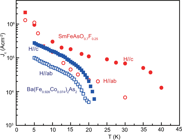
J cs (along the ab plane direction) of Ba(Fe0·926Co0·074)2As2 and SmFeAsO0·7F0·25 single crystals for an applied field parallel to the c-axis and perpendicular to the c-axis (parallel to the ab plane) calculated using Bean’s model (after Refs. 121 and 122)
Beside single crystals, the reported critical current densities include 1×10⁴ A cm−2 at 4 K of polycrystalline Ba0·6K0·4Fe2As2 prepared by the PIT method154 and 4×10⁶ A cm−2 at 4 K of BaFe2As2:Co epitaxial film grown by pulsed laser deposition.155
Figure 19 shows H
c2s estimated by Ni et al.
120 for (Ba0·55K0·45)Fe2As2 (T
c = 32 K) and by Moll et al.
121 for SmFeAsO0·7F0·25 (T
c = 48 K) where H
c2 is the upper critical field measured by applying a magnetic field to the c-axis direction (H//c) and the ab plane direction (H//ab) respectively. The measurement for a (Ba0·55K0·45)Fe2As2 (T
c = 32 K) single crystal indicates 


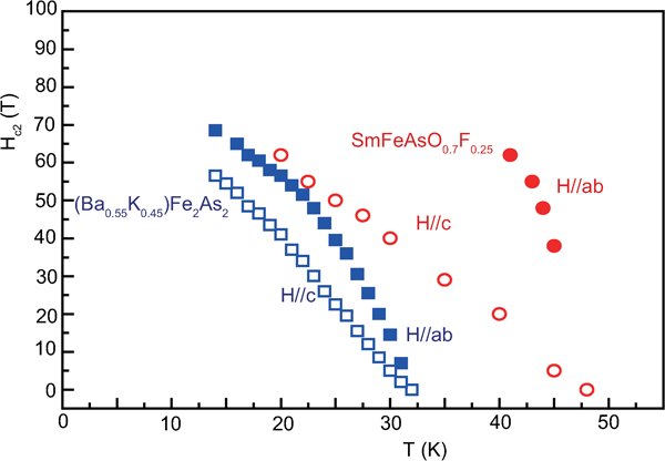
Anisotropic H c2(T) of (Ba0·55K0·45)Fe2As2 and SmFeAsO0·7F0·25 single crystals for an applied field parallel to the c-axis and perpendicular to the c-axis (parallel to the ab plane) (after Refs. 120 and 121)
Summary and outlook
We reviewed the FeSC from the viewpoint of the crystal structure and physical characteristic of bulk mainly. The research on application using thin films and wires is also important in the field of material science. The recent review by Hiramatsu et al. gives us useful information on this area.157
FeSCs typically show a high J c and H c2 with a low anisotropy and relatively high T c, which are favourable features for practical applications. On the other hand, many problems still remain; the content of toxic elements such as As or Se in FeSCs with a high T c is a serious issue, and prevents many researchers in the companies from joining the field. Hence, FeSC research must be conducted in a well controlled experimental environment. Although the record highest T c (56 K) has not been broken for 3 years, much progress has been continuing under these conditions, especially in parent materials and physics. The discoveries of KxFe2Se2 with a T c at 30 K36 noted in the section on ‘Non-stoichiometric 245-type materials (A2Fe4Se5, A: K, Rb, Cs, Tl)’ and Ca10(Pt4As8)(Fe2-xPtxAs2)5 with a T c at 38 K158 – 160 are examples of such progresses. Recently, the new type of FeSC with relatively high T c, Ca1−xLnxFe2As2, has been reported.161 The highest T c is 49 K for Ca0·8Pr0·2Fe2As2 162 or 42·7 K for Ca0·8La0·2Fe2As2.163 Because the 122-type is stable and relatively easy to prepare single crystals, many researchers are undertaking theoretical evaluations and are beginning to investigate the physical properties. Though the theoretical research to evaluate the origin of superconductivity of FeSC has also been progressed drastically, which is not discussed in detail in this review, many problems are still remaining and newly induced. Especially, the various relationships between the magnetism and the superconductivity attract the interest of many physicists. Sefat et al. introduces these relationships as ‘Puzzles’ in their review article.25
In the 1960s to early 1980s when the T c appeared to be reached the limit at 23 K of Nb3Al1−xGex, ‘Matthias’s rules’ were widely accepted as a guide to finding a superconductor with high T c.164 Through discoveries of cuprate and FeSC, no researchers adhere to these rules. Mazin165 improved set of rules to find high T c superconductors, where he noted the importance of layered structure, magnetism and controlling of carrier density.
The development of cuprate superconductors emphasised the importance of a layered structure and chemical bond. Adding to the tutorial of cuprate superconductors, the discovery of FeSCs permitted all elements to be selected including magnetic elements as Fe, Co and Ni. From this knowledge, new seeds to improve superconductors have been continually sown, such as La2Sb,166 CeNi0·8Bi2,167 LaCo2B2 168 and Ir1-xPtxTe2.169 Discovery of new materials is the mother of superconducting research!
Footnotes
Acknowledgements
This work is supported by a grant from the Japan Society for the Promotion of Science (JSPS) through the ‘Funding Program for World-Leading Innovative R&D on Science and Technology (FIRST Program)’, initiated by the Council for Science and Technology Policy (CSTP).