
Abstract
A new paradigm for understanding and applying sonographic principles is needed because two alternative fundamental principles of operation are now present in the array of commercially available sonographic equipment. The first, which is termed conventional sonography, has been the operating principle for more than 50 years. Recently, a second principle has appeared, termed virtual-beam sonography. These two operating principles are fundamentally different, and there are implications for the resulting anatomic images and motion information presented. Virtual-beam sonography improves nearly every aspect of sonographic, anatomic imaging and motion presentation.
A new paradigm for understanding and applying sonographic principles is needed because two alternative fundamental principles of operation are now present in the array of commercially available sonographic equipment. Two definitions for paradigm are the following:
a set of assumptions and rules that guide workers in a specific field and
an approach to how something should be thought about or understood.
Definition 2 is relevant to this article. Because there are two fundamentally different operating principles present in currently available sonographic systems, a new approach to sonographic principles is necessary. For more than 50 years, one principle has been operating. Now there are two. Both must be understood and included in educational curricula, testing, certification, and clinical implementation.
The term sonography is composed of two words from two languages: the Latin sonos, meaning “sound,” and the Greek graphein, meaning “to write.” Thus, sonography is writing with sound, a fact that readers of this journal know well. The fundamental pulse-echo principle that has been in use for decades states that a pulse of ultrasound is sent into the anatomy to be imaged, and the returning echo stream is displayed as a visible scan line, which is another fact that readers of this journal know well. This is repeated about 100 to 250 times to form one frame of the anatomic image. In conventional sonography, there is a one-to-one correspondence between an emitted pulse and the returning echo stream that appears as a scan line on the display (ignoring the detail that, in some cases, multiple scan lines can be presented from one emitted pulse, typically two or four). Readers of this journal know that the best detail resolution occurs in the focal region of a focused, transmitted beam. A laser-thin beam would produce excellent detail resolution everywhere in the image. Unfortunately, the high frequencies necessary to produce such a beam would not allow the penetration necessary for human anatomic imaging. Conversely, an unfocused beam would produce a useless image with unacceptable detail resolution throughout. In conventional sonography, a longer effective focus can be achieved with multiple focuses, improving detail resolution but at the expense of degraded temporal resolution. For example, three transmit focuses require three pulses per scan line, rather than one, slowing the acquisition process and reducing the frame rate to one-third what it would have been with a single focus.
For more than 50 years, sonographic systems have operated with the straightforward pulse-echo principle, termed conventional sonography in this article. 1 Now, newer and more sophisticated sonographic instruments have appeared that operate on an entirely different principle, termed virtual-beam sonography in this article.2,3 The emergence of this new principle has necessitated development of a new paradigm for understanding, teaching, testing, and applying sonographic principles. This new paradigm recognizes the existence of these two operating principles and accounts for both in teaching and applying sonographic principles. This article describes differences between the old and the new operating principles, shows how the new principle works, and presents several improvements implemented with the new principle.
Progression of Conventional Sonography: Features and Technologies
Over the past 50 years of the development of sonography as we know it today, features have appeared at various times (Table 1). First, there was A mode, which presents the echo amplitude as a function of depth. Then there was M mode, which presents echo depth as a function of time. Then static black-and-white, two-dimensional (2D) anatomic imaging appeared, followed by static gray-scale, 2D imaging and then real-time, gray-scale, 2D imaging. Then digital memory and processing arrived followed by color Doppler flow imaging and spectral Doppler analysis and display. Later, static three-dimensional (3D) imaging arrived followed by real-time, 3D imaging (or so-called “4D”). Then contrast agents became practical and approved for clinical use, and finally, elastography appeared, moving sonography into the realm of qualitative “virtual palpation.”
Features and Technologies Associated With Conventional Sonography.
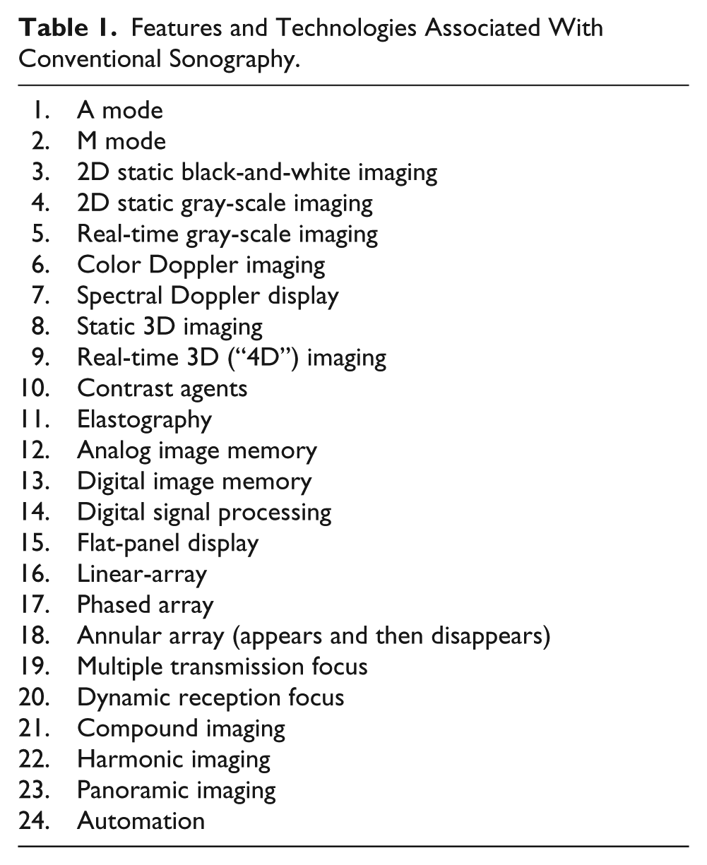
During the same period of progressive development, technologies appeared that included linear-arrays, convex arrays, phased arrays, annular arrays (which later disappeared), multiple transmission focus, dynamic reception focus, flat-panel display, compound imaging, harmonic imaging, panoramic imaging, 2D arrays, and automation.
All of these features and technologies have developed while operating with the conventional pulse-echo principle.
Conventional Pulse-Echo Principle
Physical beam forming, directly coupled with displayed scan lines, has historically been the conventional operating principle of sonographic systems. In this principle, there is a one-to-one correspondence between the echo stream from an emitted ultrasound pulse and its displayed scan line, although, in some cases, multiple scan lines can be presented from one emitted pulse, typically up to four. But, even then, there is a direct correspondence between emitted pulses and displayed scan lines. Ignoring this special case, if there are 200 scan lines in an image, it takes 200 emitted pulses to produce that image, and the time to produce it (T) is equal to the time to receive the echoes from each pulse × 200. The frame rate, then, is 1/T. The best detail resolution occurs in the focal region of a focused transmitted beam (Figure 1A, B). If multiple transmit foci are used to provide improved detail resolution over a longer range of depths, the frame rate drops proportionally to the number of focuses. Thus, an improvement in detail resolution comes at the expense of degraded temporal resolution. Remarkably, with the virtual-beam–forming principle, the result is as if the transmitted beam were thin, when in fact it was weakly focused or unfocused (Figure 1C, D)! The sequence of events to produce one image frame in conventional sonography is shown in Figure 2A.
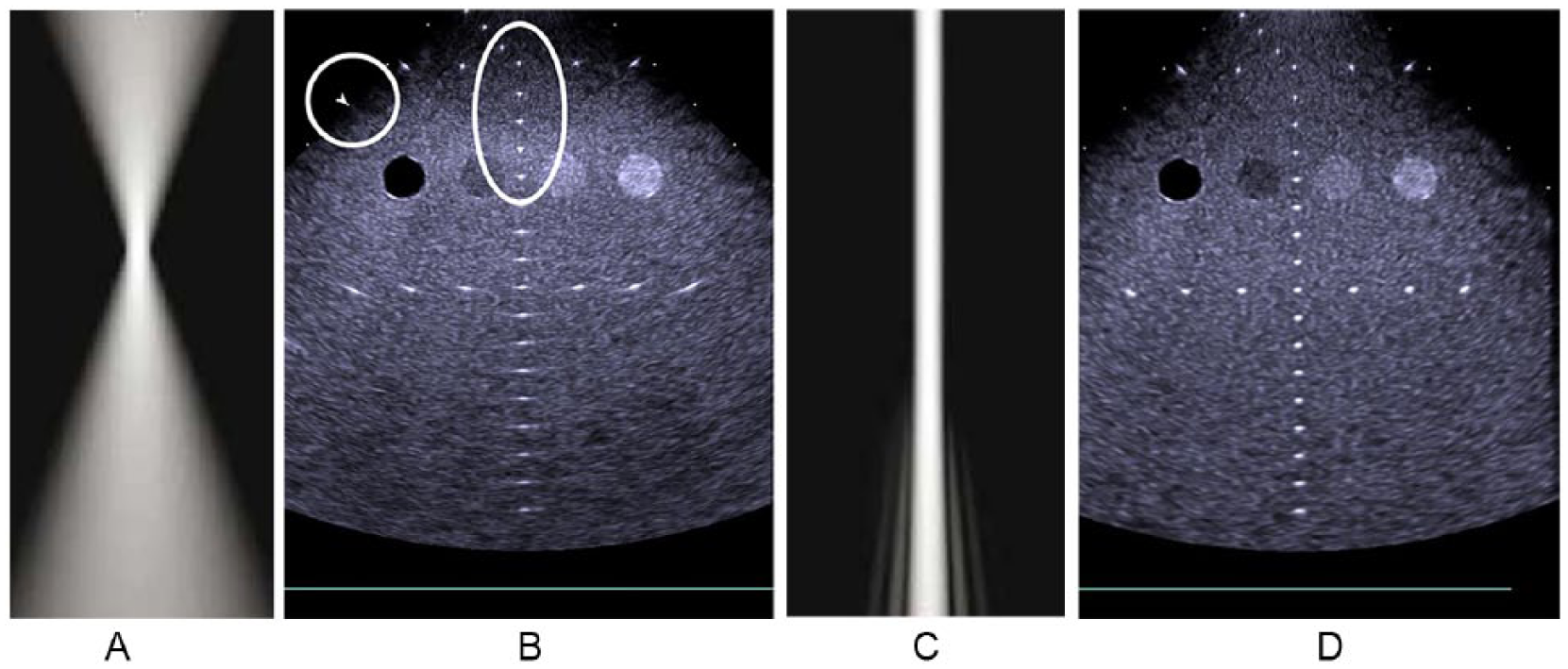
(A) Conventional focused transmitted ultrasound beam. (B) Image of a tissue-equivalent phantom. The nylon lines are shown as dots in the focal region (oval) as indicated by the arrowhead (circle). Deep to the focal region, the lines smear laterally as the lateral resolution (and, thus, the detail resolution) degrades. (C) Effectively narrow transmitted beam with virtual-beam forming. (D) Excellent detail resolution throughout the image with virtual-beam forming. A and C courtesy of Philips Healthcare. B and D courtesy of Siemens Healthineers.
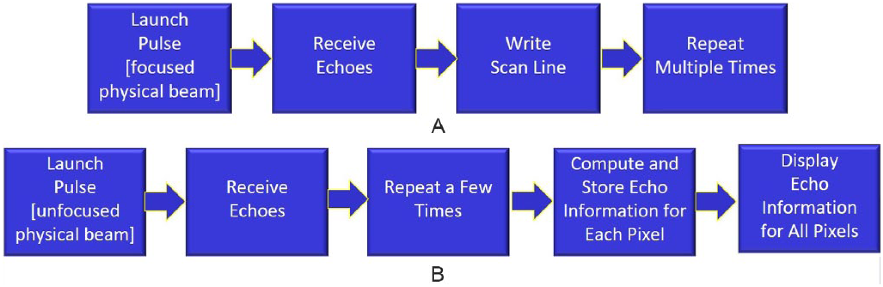
(A) Sequence of operations for conventional sonography. (B) Sequence of operations for virtual-beam sonography.
Virtual-Beam–Forming Principle
Newer, more sophisticated instruments operate on the virtual-beam principle, in which fewer pulses are required and focusing is not necessary (although some focusing is needed in some applications such as harmonic imaging and contrast-enhancing agents), and yet the entire image is in focus with higher frame rates. Unlike conventional sonography, with this principle there is no direct relationship between the number of scan lines displayed and the number of transmitted pulses required to produce the image. The sequence of events to produce one image frame in virtual beam-forming sonography is shown in Figure 2B. The image processor in the conventional instrument is replaced by the image former in the virtual-beam system. The image former accomplishes the retrospective virtual-beam computations.
Virtual-Beam–Forming Implementation
How is the computational step 4 in Figure 2B accomplished? The details are complicated and proprietary, but the process can be understood conceptually as follows.
Recall the principle of dynamic reception focus as implemented in conventional sonography, where, as echoes are received from a transmitted pulse, the reception side of the beam former arranges the delays in the various channels to focus on reception at a particular depth. The focus follows the increasing depth of origin of echoes as they return following pulse launch (Figure 3A, B). This principle is extended in virtual-beam sonography to retrospectively and computationally locate the reception focus at every pixel location in the image after echo information has been received for the entire image (Figure 3C, D, E). Thus, the echo information is computed retrospectively after the entire frame has been acquired. This is in contrast to the line-by-line sequential process of the conventional pulse-echo principle. The computed image can be thought of as produced by virtual beams similar to laser-thin emitted physical ultrasound beams. Such a physical beam can be produced at extremely high ultrasound frequencies (hundreds of MHz) but with very little penetration. In fact, ultrasonic microscopes are commercially available that do produce such images, but they are limited to pathology-type applications and require thin sections of tissue, as with light microscopy. Even if such beams could penetrate to the depths required for diagnostic sonography, they would still require a pulse for every scan line in the image. This is not the case for virtual-beam sonography, which allows frame rates to be much higher, producing improved temporal resolution. Thus, virtual-beam sonography is actually superior to laser-thin transmission-beam sonography (if it were possible), because it yields significantly improved detail resolution and temporal resolution (along with several other advantages, as detailed in the next section).
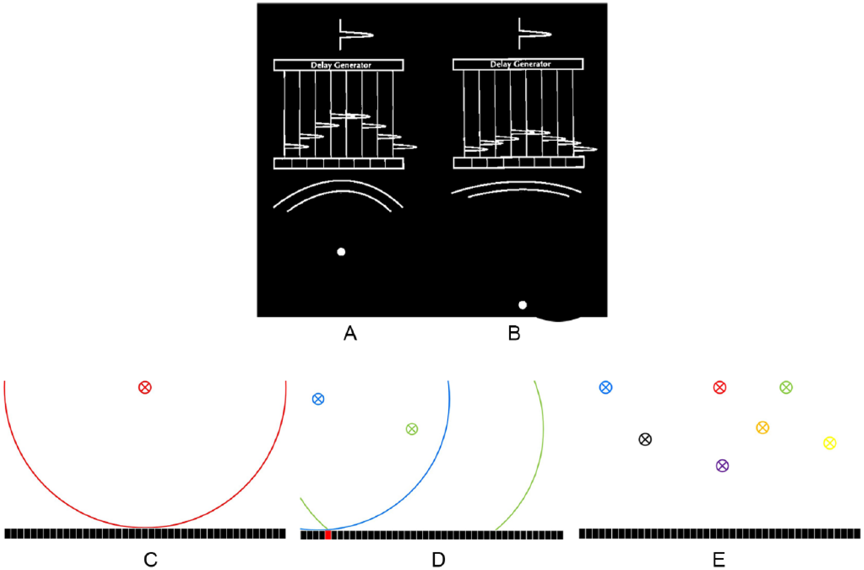
Dynamic reception focus provides continuous focusing when a stream of echoes is being received. (A) An early echo has a lot of curvature to it. The delay generator delays the voltages in the channels so that they all line up to provide a short (for good detail resolution) and strong (for good sensitivity) voltage representing the echo. (B) An echo from a deeper reflector has less curvature. The delay generator again delays the voltages (with less delay than in part A) so that they line up for a short, strong result. The delay pattern continually changes as the echo stream returns (with decreasing curvature) to the transducer to maintain a dynamic reception focus at all depths. (C, D, E) Retrospective, virtual-reception-beam forming conceptually. (C) An echo from the red x arrives at the transducer elements with the curved pattern as shown by the red line. Central elements receive the echo first. As the echo continues to arrive, elements receive it in rapid sequence from center to both edges. (D) Echoes from locations indicated by blue and green x’s arrive with sequential patterns different from each other and from that in part A. Note that the echoes arrive simultaneously at the red transducer element. (E) The arrival sequence is unique to and can be used to identify the echo from each pixel location. The challenge in doing this is that echoes are arriving from many locations simultaneously in a mixed-up condition. The retrospective beam-forming process must unsort all these arriving patterns to determine what arrived from each pixel location. This is a complicated computational process, but because of the speed of the graphics processing units, it can now be accomplished at real-time frame rates.
Virtual-beam forming is accomplished through massive, parallel, high-speed, computational postprocessing using graphics processing units. 4 A total of 500 billion calculations per second make this retrospective beam-forming practical in real-time. Physical beam forming is still necessary with virtual-beam sonography, but it is no longer coupled directly to displayed scan lines. Rather, the images can be thought of as produced by virtual beams. Virtual beam-forming significantly improves nearly every aspect of sonographic, anatomic imaging and Doppler motion detection and presentation as follows.
Improvements in Anatomic Imaging and Motion Presentation Using Virtual-Beam Forming
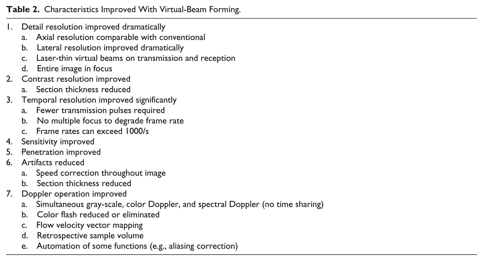
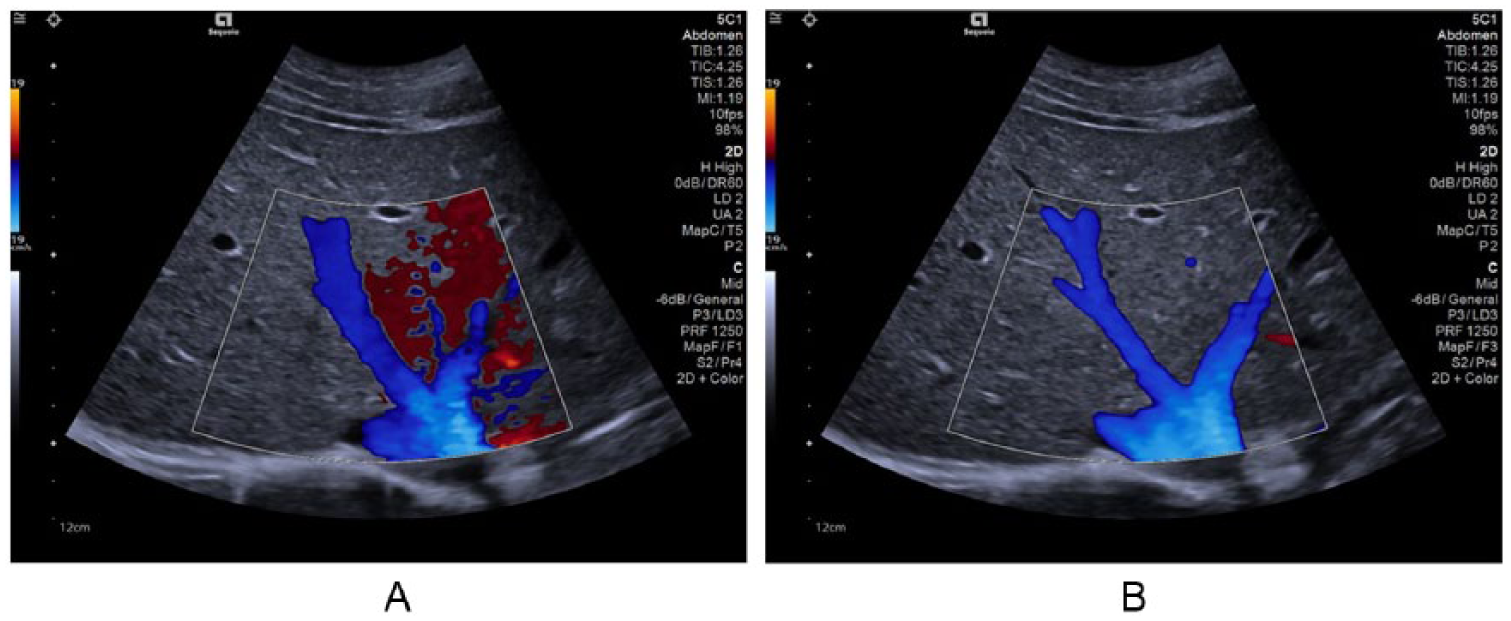
The characteristics that are improved with virtual-beam sonography are listed in Table 2. In contrast to conventional sonography, in which improving one characteristic requires degrading another (the only exception being dynamic-reception focus), all of these characteristics are improved with the virtual-beam approach. They include detail resolution 5 (Figures 1 and 4), contrast resolution, temporal resolution (enabling real-time 3D imaging and quantitative elastography; Figure 5), sensitivity and penetration, artifacts (reduced), and Doppler operation, 6 in which simultaneous gray-scale, color Doppler, and spectral Doppler are enabled (i.e., time sharing between these operations is no longer required) enabling high frame rates (Figure 6A), multiple retrospective sample volumes (Figure 6A, B), vector flow-velocity mapping (Figure 6C, D) and reduction or elimination of color-flash artifact (Figure 7).
Characteristics Improved With Virtual-Beam Forming.
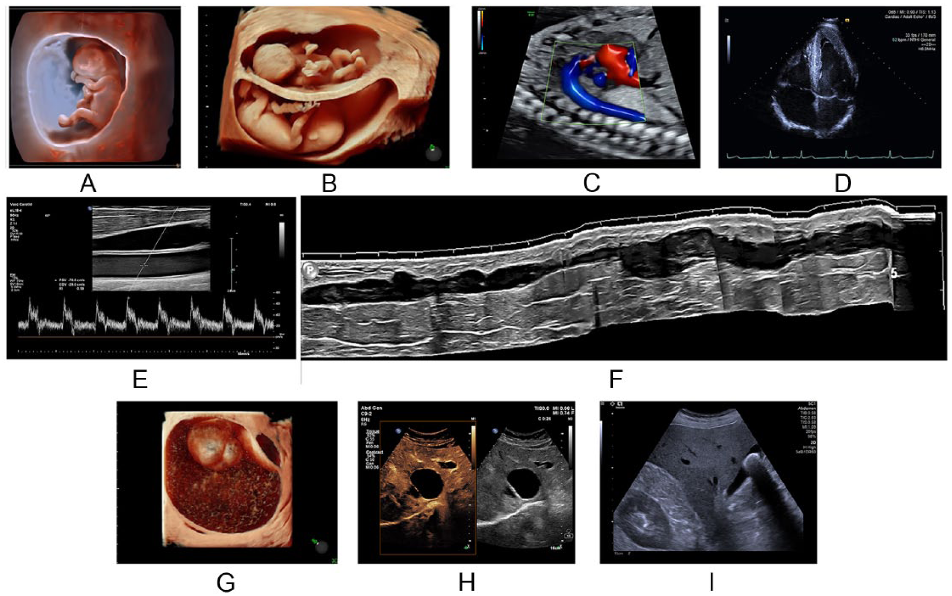
(A) Early-gestation fetus. (B) Twins. (C) Flow in the fetal heart and descending aorta. (D) Cardiac image. (E, F) Vascular images. (G) Ovarian mass. (H) Hepatic cyst. (I) Abdominal image. A, E, F, and H courtesy of Philips Healthcare. B, C, and G courtesy of GE Healthcare. D and I courtesy of Siemens Healthineers.
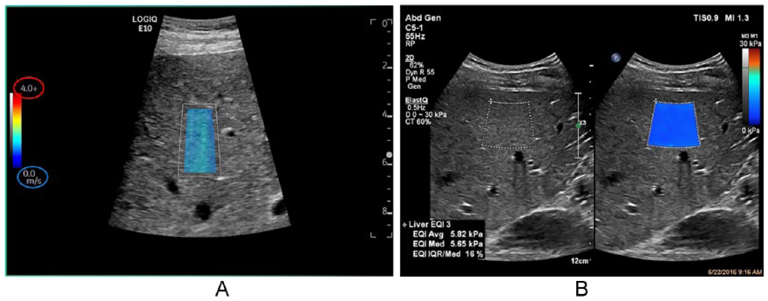
Quantitative elastography. (A) The scale is calibrated in m/s shear wave propagation speed. Courtesy of GE Healthcare. (B) The scale is calibrated in kPa stiffness units. Courtesy of Philips Healthcare.
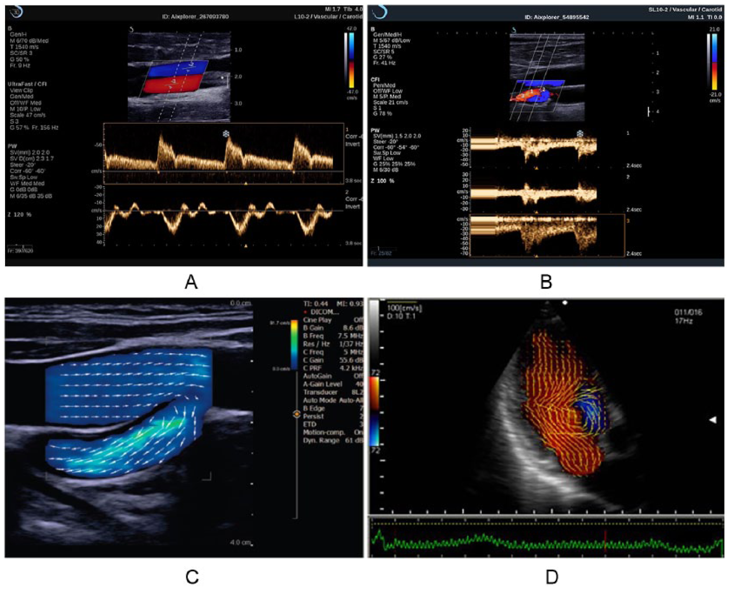
(A) Retrospective sample volumes from saved color Doppler image. Sample volume 1 (upper spectral display) shows flow in the artery. Sample volume 2 (lower spectral display) shows flow in the vein. Note that the color Doppler frame rate is 156 Hz (frames/s). Courtesy of SuperSonic Imagine. (B) Three sample volumes and spectral displays. Note that the gray-scale frame rate is 41 Hz. Courtesy of Daniel A. Merton, BS, RDMS. (C) Vascular vector-flow image. The arrows indicate flow speed and direction at each location in the flow. The color scale is calibrated in cm/s. (D) Cardiac vector-flow image. C and D courtesy of Carestream.
Abdominal image with color Doppler. (A) Red is flash artifact. (B) Flash artifact eliminated. Courtesy of Siemens Healthineers.
Implications
What does all this mean for students, educators, testing organizations, sonographers, and physicians?
For students, it means that a new paradigm (remember, it is an approach to how something should be thought about or understood) now exists within which students must learn about two principles of operation, their differences, and the impacts of each on the resulting sonographic imaging.
For educators, it means that these two principles and the differences in the resulting image characteristics must now be included in their curricula and testing.
For testing organizations, the new principle must now be included in their testing schemes. Some questions will apply to both principles with the same correct answer. Some questions will apply to both principles with different answers. Some questions will not apply to both principles but only to one or the other.
For sonographers, systems will be encountered that are operating on the conventional pulse-echo principle and others that are operating on the virtual-beam–forming principle. The new principle assists with image optimization and will even assist with image acquisition. Differences in operation and resulting imaging characteristics will be encountered. Familiarity and comfort with both will be required, and switching back and forth may be necessary during a transition period in which both are present in a clinical facility.
For physicians, images that look different than what is familiar will appear with the new principle. Images with the new principle are of higher quality and assist with the accuracy of diagnosis and efficiency of clinical work flow. Adjustment to interpreting these images will be necessary. During the transition when both principles are operating in a clinical facility, reading and interpreting differing types of images will be experienced. Operating in such an environment will require the development of expertise and comfort with images generated by both principles of operation.
Conclusion and the Future
Of the many tasks sonographers perform in their daily responsibilities, two primary ones are (1) the acquisition of images and (2) their optimization. The virtual-beam–forming principle assists primarily with the second responsibility. We are now in an unknown period of years in which sonographic systems fall into two classes of operation that are fundamentally and dramatically different. Weakly focused or unfocused beams can now produce images that have excellent detail resolution throughout the image, with higher frame rates and improved imaging in nearly every aspect of anatomic and motion presentations. When conventional-principle systems are no longer produced and marketed, how long will it take for those thousands of systems to be replaced? No one knows. And long before then, there will probably be another principle of operation (Figure 8), and maybe more than one. With artificial intelligence, machine learning, and deep learning already penetrating sonographic technology, who knows how these systems will be operating in 5 or 10 years? Tasks (1) and (2) are already being assisted and improved by these techniques. In any case, now that there are two principles of operation present in sonographic technology, students, educators, sonographers, and physicians must understand the differences in these operating principles and their impacts on anatomic imaging and motion information and also be prepared for more dramatic changes in how these systems operate in the future. We have entered a new era in which not only is there a new operating principle present but a rapidly changing environment in which systems will be operating in ways that we have neither experienced nor conceived. Keeping up will require greater effort in continuing education and adjustment than previously required. Thus, the necessity for Your New Paradigm for Understanding and Applying Sonographic Principles.
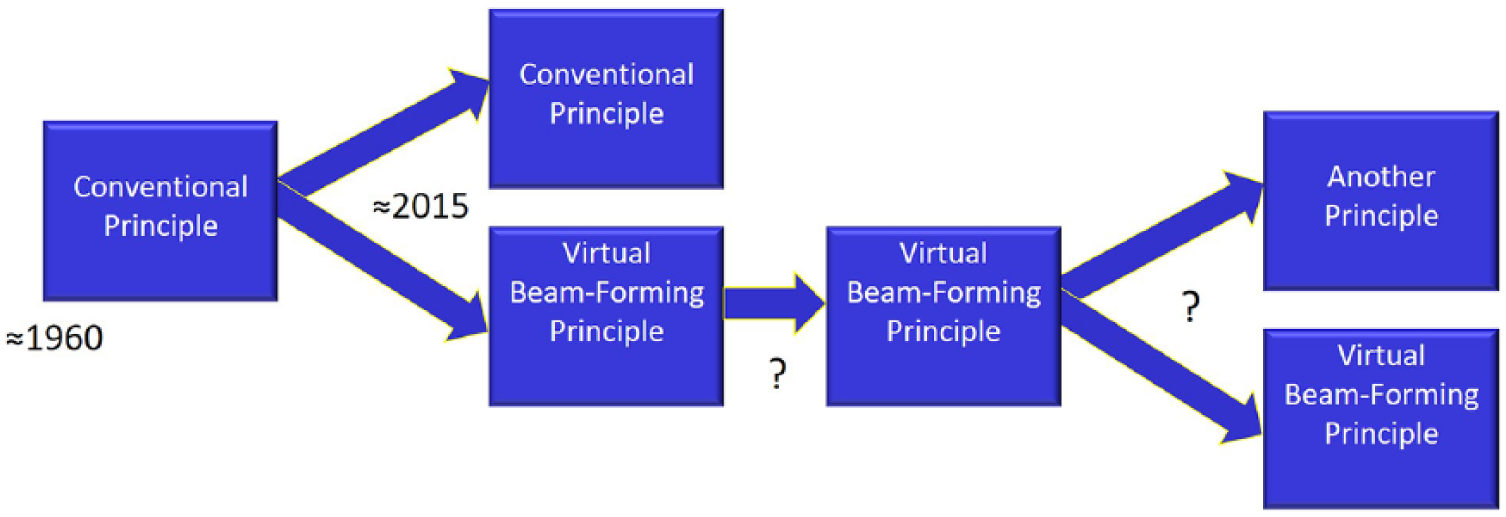
For more than 50 years, there was one principle of operation in sonography (the conventional pulse-echo principle). We are now in a period of an unknown number of years in which there are two principles of operation. At some future time, systems operating on the old principle will have been retired, and only systems with virtual-beam forming will be in use. Or by then, there may (will?) be another principle of operation in use or possibly more than one.
Footnotes
Acknowledgements
Enlightening and clarifying discussions with Kevin D. Evans, Amy Lex, Nancy Plambeck and the following engineers are gratefully acknowledged: Russ Behler, Brian Lause, Brian Mceathron, and Larry Mo at GE Healthcare, Anup Agarwal, Rob Entrekin, Jim Jago, and Neil Owen at Philips Healthcare, John Benson, Stirling Dodd, Heather Mareth, Rick Loftman, and Andy Milkowski at Siemens Healthineers.
Authors’ Note
Presented in plenary session at the SDMS Annual Conference, October 5, 2018.
Declaration of Conflicting Interests
The author declared no potential conflicts of interest with respect to the research, authorship, and/or publication of this article.
Funding
The author received no financial support for the research, authorship, and/or publication of this article.