
Abstract
Diagnostic medical ultrasound transducers have evolved through the years and have contributed significantly to improved patient care. This article discusses the history and types of transducers and the elements that have changed over time. There has been a sharp transition from natural to human-made elements and from one to many in a single transducer. Ergonomics also now plays a role in transducer design and will continue to do so; the grip, weight, and size of transducers are in the forefront of design considerations. The evolution of transducers has changed not only how well we visualize anatomy and what anatomy we see but also how the patient’s care is managed. Different, new, and emerging technologies certainly will continue to be identified within the sonography community.
The advancement in transducer technology has had a profound impact on ultrasound imaging, allowing evolution from A-mode to real-time B-mode to 4D imaging. Where previously sonographers may have been limited to a single probe, today an extensive array of six or seven transducers, or more, may be available. The advancements and improvements in probe technology are discussed in parallel with the background history of ultrasound transducers.
History
In the broad sense of the word, transducers are simply devices that convert one form of energy into another. Such devices have been recognized throughout history, including Pythagoras in 550
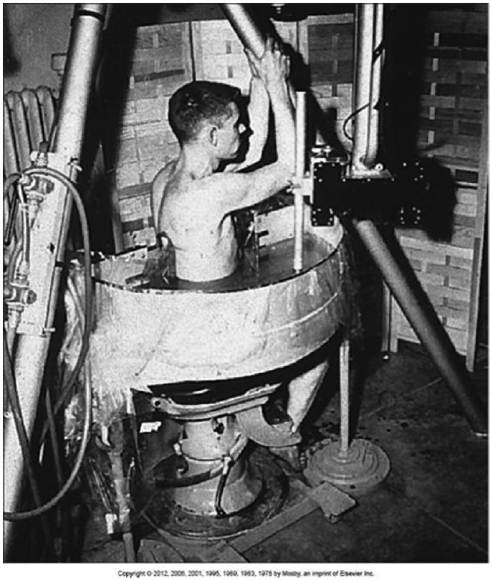
Photograph of the original Pan-scanner of Holmes et al 5 designed to allow ultrasonic visualization of the soft tissue structures of the human body. (Reproduced with permission; originally published in Hagen-Ansert SL: Foundations of Sonography. In Hagen-Ansert SL: Textbook of Diagnostic Sonography, 7th Ed, pgs. 2-20, Copyright Elsevier Mosby (2012).
Nondiagnostic applications of ultrasound transducers also developed over this period. Therapeutic transducers utilize high-intensity sound waves to provide a source of tissue heating secondary to absorption of the pressure waves, routinely done in physical therapy departments. Focused high-intensity transducers are used therapeutically to destroy tissue by either heat or the direct mechanical effects of the pressure wave, as seen in lithotripsy for kidney stones (first proposed by Uchida and Oka in the 1970s) or more recently in high-intensity focused ultrasound systems.22-28
Transducer Elements
Transducers use active elements, either natural or manufactured, to create the piezoelectric effect needed for sonography. Early transducers that used the piezoelectric effect typically had some form of quartz as the active medium. 3 Found naturally in the environment, quartz is relatively plentiful, and its crystalline properties make it a good choice. 1 Quartz crystals also were found readily in the United States as well as in large quantities in Switzerland. Tourmaline is another natural element that has been used in transducers, found in Southern California and Brazil, among other places in the world. 29 Manufactured piezoelectric materials have included barium titanate, lead zirconate titanate (commonly abbreviated PZT, the most popular choice and particularly used for Doppler transducers), barium lead zirconate, lead metaniobate, and polyvinylidene fluoride. The desirable attributes of these materials are a high coupling coefficient, a high frequency of natural resonance, and repeatable characteristics for stable designs. 30
As originally described, piezoelectricity is the response of certain materials that, when deformed by pressure, a voltage is produced. 31 It was realized later in the 19th century that a reverse piezoelectric effect was also possible; that is, when a voltage is applied to the material, it deforms in a reproducible fashion. To manufacture a piezoelectric material, the raw material is placed in a strong magnetic field at a high temperature, referred to as the Curie point, where the material’s basic structure is aligned in such a way as to produce the piezoelectric effect. As a cautionary note, if the temperature exceeds the Curie point, the piezoelectric effect is lost: do not attempt to sterilize transducers in an autoclave or any other source of elevated temperatures. More modern-day composite transducer elements are then created by cutting the piezoelectric material in a predefined pattern, with the resulting gaps among the small individual elements produced filled with some type of epoxy resin. The size and shape of the cuts are done with the final application in mind, as they determine the element’s acoustic impedance as well as its resonant frequency and focusing characteristics.
The center, or resonant, frequency of an element is determined by the propagation speed of the material used and its thickness 8 :

For PZT used in diagnostic medical ultrasound systems operating anywhere from 2 to 15 MHz, the element thickness is typically a fraction of a millimeter. Once the elements are formed and shaped, matching layers are guilt into the transducer to allow effective coupling of the pressure waves created by the piezoelectric effect to the tissue. These matching layers (including acoustic gel) gradually match the impedance of the active element to the tissue to avoid massive reflections at the tissue interface and loss of transmission/reception. A backing or damping material is bonded to the back of the element to prevent persistent “ringing” of the active element when excited to produce a short pulse, necessary for good axial resolution when imaging. A typical backing material has been a type of epoxy resin with tungsten filaments. 31 The next layers of a transducer are made up of acoustic and electric insulators. Acoustic insulators prevent external vibrations from causing a voltage in the active elements. Electric insulation is necessary both to shield the internal components from any outside electromagnetic interference and to prevent electric leakage from the elements to the sonographer. Finally, all of these layers are housed in a molded plastic case, allowing the user to grip the transducer securely during an examination.
Types of Transducers
Transducer design for imaging systems has undergone significant evolution over the years, from simple fixed single crystals to mechanically scanned elements and now to a variety of multielement arrays—linear, phased, annular, curvilinear, 2D, and so forth. 31 The older single-element and mechanically scanned transducers had a fixed focal depth determined by the transducer design. Internally focused transducers relied on either a curved active element or a curved internal mirrored surface to provide a focal point. External focusing could be accomplished as well by incorporating an acoustic lens into the transducer design. Despite their relative advantage of a small footprint and lack of expense to manufacture, these transducers are rarely used today for diagnostic sonography because of their fixed focus and the fact that if the single crystal element fails, the entire transducer fails.
Multielement array transducers allow greater flexibility in applications, as each element can be fired independently and the resulting ultrasound beam shaped, steered, and focused electronically to achieve the desired outcome. If desired, multiple elements can be activated as a group to provide the desired beam characteristics. (The exception to this would be an annular array transducer, consisting of multiple elements arranged as concentric circles. Focusing is done electronically for these transducers, but steering is done mechanically. Another “exception” would be a continuous-wave Doppler transducer consisting of two active elements, one continuously transmitting and the other continuously receiving, with no imaging capability.)
Three-dimensional imaging is now possible as well; when the resulting frame rate is high enough to be considered close to real time, it becomes “4D” imaging. The earliest 3D transducers combined linear multielement arrays for two of the dimensions, with a mechanical (or manual) scan for the third dimension, allowing a volume of image data to be captured for processing.31-34 This volume data set is the collection of the 2D images organized in the third dimension much like the pages in a book (Figure 2). Manual freehand scanning in the third dimension can be used to create a 3D image, the result of which is sonographer dependent and qualitative. For quantitative anatomic measurements, a manual scanned system needs some type of electromagnetic transducer tracking system to provide positional information; mechanically scanned multielement arrays will have this positional information sensed electronically. Manufacturers have recently been able to produce 2D arrays of piezoelectric elements, or matrix arrays, which are capable of producing 3D images entirely through electronic manipulation of the elements, removing the need for any mechanical devices or other tracking mechanisms (Figure 3). While these mechanically scanned arrays or matrix array transducers overcome many of the limitations of sonographer dependence, eliminate most motion artifacts, and provide close to real-time quantitative images, they are very costly and are not yet used routinely outside the field of obstetric scanning.21,33,34
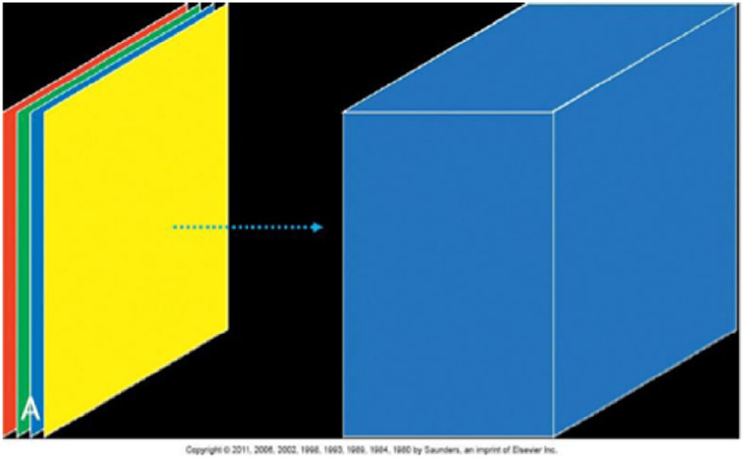
Schematic diagram of the capture of successive 2-dimensional images during a 3-dimensional scan, similar to the pages of a book. (Reprinted with permission from Kremkau FW (Ed). Sonography Principles and Instruments. 8th ed. St. Louis, MO, Mosby, 2011)
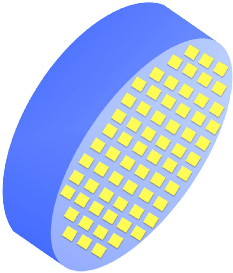
Schematic diagram of a 2-dimensional array of piezoelectric elements, which allows fully electronic control to capture a 3-dimensional image.
For all of the multielement imaging transducers discussed above, one aspect of current research is concentrated on growing a single uniform piezoelectric crystal large enough to be used for any intended application. A small seed crystal is used to start the process; this seed crystal is then grown under very controlled conditions and enlarged in layers before it is polarized and cut/sliced into the desired elements. There are numerous advantages to this approach, as the resulting transducer will have very uniform properties and characteristics with more efficient conversion of electric impulses to pressure waves and vice versa. This makes beamforming and focusing more precise while increasing overall transducer bandwidth and sensitivity to allow imaging at greater depths through relatively high transmit frequencies to enhance spatial resolution. 35
Ergonomics
Ergonomics and sonography have become terms frequently used in the same sentence. Studies have shown that 80% to 90% of sonographers scan in pain and 20% will have career-ending injuries.36-38 Direct and indirect expenses from musculoskeletal disorders cost approximately $60 billion per year according to the Bureau of Labor and Statistics. 36 Manufacturers have recognized this problem and have applied many ergonomic design considerations to today’s transducers. Transducer housings are more and more being designed to accommodate a neutral wrist position, with the center of gravity within the center of the hand. They are being made narrower and smaller such that today’s transducers are significantly lighter in weight than their older counterparts and are shaped to better accommodate users’ hands, be they small or large, left or right. 37
Common injuries associated with transducers that are not ergonomically designed are tendonitis and tenosynovitis, de Quervain disease, carpal tunnel syndrome, and trigger finger. 36 Key to avoiding these injuries are a well-designed transducer coupled with good sonographer technique. 39 A frequent error in scanning is using too strong a grip on the transducer, especially when only light pressure is necessary. Newer transducer designs help avoid overstretching of the fingers or excessive pinch gripping. Transducer cables are also becoming lighter in weight, and a variety of stress-relieving arm braces are available to reduce the tension on the hand, wrist, and forearm. While acoustic gel is necessary for imaging and gloves are an essential part of universal precautions, both of these can make a transducer difficult to hold securely and firmly without excessive grip pressure, particularly if the gloves are not sized properly. Ideally, a glove should fit snugly and have a nonslip texture to complement the same texture on the transducer housing. A concept under development is a finger-mounted transducer that is affixed to the sonographer’s finger to maximize control for such examinations as guided biopsies and peripheral vascular studies. The cable for the transducer is attached to the operator’s arm to eliminate torque and other forces on the sonographer’s wrist.
Future Directions
The future of ultrasound transducer development is one of continuing improvement and evolution. One can now attach a transducer to a smart phone to use it as an ultrasound machine while maintaining all the communication capabilities of the original phone. 40 This allows rapid transmission of images to other sites for more detailed interpretation or, in settings such as trauma and combat, to allow for earlier preparation for patient management. Such devices increase the portability of ultrasound beyond even the scope of laptop computer–sized instruments and potentially make ultrasound as ubiquitous as smart phones themselves.
Wireless transducers are another area of interest for development. There are several limitations yet to be overcome, such as the need for a power source in the transducer itself (increasing size and weight) and the need to transfer very large data sets quickly to the primary ultrasound machine. However, the advantages of markedly increased portability and the absence of a cumbersome cable are clear enough that efforts are certain to continue in this area.
Transducer element technology may also undergo a major change in the future as the technology of capacitive micromachined ultrasonic transducers is more fully developed. 41 Capacitive micromachined ultrasonic transducers are based on etching on a silicon surface, very similar to today’s integrated circuits, and theoretically allow the placement of orders of magnitude more active elements in both 2- and 3D arrays in the transducer housing. Electronic manipulation of these arrays will provide even more dynamic and flexible imaging capabilities by a transducer, with a lower cost and a wider bandwidth and with better temperature stability than current transducers.
Conclusion
There is no doubt that transducer technology is advancing rapidly and taking advantage of the progress made in the areas of circuitry and computing. Certainly improvements in transducer technology have had a profound impact on image quality and the increasing role that sonography plays in medical diagnosis and patient management. A wider variety of anatomy can be imaged, and diagnoses can be made earlier and/or with more certainty, thereby reducing the need for further, more expensive, and invasive testing.
Footnotes
Declaration of Conflicting Interests
The author declared no potential conflicts of interest with respect to the research, authorship, and/or publication of this article.
Funding
The author received no financial support for the research, authorship, and/or publication of this article.