
Abstract
This article presents the recorded and modeled strong-motion response of a long (1.35 km) bridge located in Wellington, New Zealand during multiple sequential earthquakes. These were some of the first recordings of this kind for a New Zealand highway bridge and add to the limited database of bridge superstructure strong-motion responses recorded worldwide. The bridge experienced little damage during the earthquakes; however, analysis of the recorded responses showed the fundamental period of the bridge varied by up to 15% across these events, highlighting the system softening that can develop without any significant structural damage. Numerical models of a single bridge pier using a p-y spring foundation modeling approach were able to represent the changes in the recorded bridge pier response across the events based on multiple response metrics, suggesting that system softening was primarily due to nonlinear soil response and concrete cracking. A sensitivity analysis showed that concrete strength and the characteristics of the upper soil layers had the largest influence on the model response. Given the presence of several strong-motion stations in close vicinity to the bridge, the sensitivity to ground-motion input was also investigated. This was shown to have a more significant influence on the modeled response than the other modeling uncertainties evaluated here, with the variability in estimated deformations highlighting the difficulties involved in the back analysis of the response of structures.
Keywords
Introduction
Several bridges around the world have been instrumented with monitoring systems that are able to capture their in-service dynamic response characteristics. This monitoring provides information that helps improve our understanding of the response of bridge systems, the validity of design assumptions, and track progressive changes in condition and performance over time. Monitoring systems typically record continuously, providing long-term records of low-amplitude ambient response, while also capturing the response during shock events, such as storms and earthquakes.
While these monitoring systems can aid in decision-making regarding bridge functionality following an earthquake, there is an inherent challenge in determining what changes observed in the response are a result of the event or arise from sensitivities in the monitoring and modeling approaches used to assess the bridge. Ambient records are often used to characterize modal characteristics using system identification approaches, with application to long-term records revealing how these characteristics can change as a function of environmental and bridge conditions (Abdel-Ghaffar and Scanlan, 1985; Cunha et al., 2001; Fujino et al., 2000). Studies on the influence of damage (Ali et al., 2019; Peiris et al., 2020) and collision impact detection (Peiris et al., 2020) on bridge response showed that damage to bridges is not restricted to changes at a material level, but could be extended to the boundary conditions and system connectivity. Brownjohn et al. (1989, 1992), Jones and Spartz (1990), and Omenzetter et al. (2013) showed that bridge damping can be sensitive to the presence of wind flow around the structure and the vibrational intensity of the bridge. Although data from ambient response can provide information relevant to the bridge dynamic response characteristics, it does not provide any information on the bridge response for loading approaching or exceeding the design level resulting from strong and sudden excitation during shock events.
The response of bridges during strong earthquake motions has had less attention in previous research due to the limited number of events recorded at instrumented bridge locations (Smyth et al., 2003). Previous analyses of the recorded response of bridges showed the abutments and embankments were the major contributors to the transverse response characteristics (Ganev et al., 1998; Smyth et al., 2003; Werner et al., 1987). Studies focused on the influence of soil–structure interaction showed there can be a change in fundamental period due to the changes in boundary conditions that are not necessarily associated with structural damage (Ganev et al., 1998; Gomez et al., 2013; McCallen and Romstad, 1994). Siringoringo and Fujino (2008) and Siringoringo et al. (2014) showed that damage of the connections between structural elements can result in the nonlinear response observed during the earthquakes. Some studies on bridge monitoring data have shown that the stiffness of the structure can change following earthquake loading due to structural damage and soil gapping and soil nonlinearity, altering the dynamic response of the structure (Beskhyroun et al., 2015; Ganev et al., 1998). In general, recorded bridge monitoring data can inform updates of bridge seismic design codes, improve the accuracy of the existing numerical models, and the criteria for ground-motion selection. However, this review suggests there are a limited number of examples of recorded response of bridges during moderate or higher intensity excitation during earthquakes, and no examples of this level of excitation across multiple earthquakes.
Laboratory-based shake-table testing has enabled the testing of scaled bridge systems of various forms under varying excitation intensities, successive earthquake records, and biaxial excitation (Johnson et al., 2008; Saiidi et al., 2014; Shoushtari et al., 2019; Thonstad et al., 2016). These tests have provided insight into some of the key aspects controlling bridge response and extended the learnings coming from the recorded response of in-service bridges. One drawback of these studies is that they have not been able to replicate in-service boundary conditions, including those related to soil–foundation–structure interaction effects.
This article presents the recorded and modeled response of the Thorndon Overbridge in Wellington, New Zealand during multiple earthquakes with moderate excitation levels. The characteristics of the bridge and the monitoring instrumentation locations are first presented. The free-field ground motions and the response of an instrumented bridge pier within the Thorndon Overbridge during multiple earthquakes are then discussed. The details of numerical models of the bridge pier using a p-y spring foundation modeling approach to account for nonlinear soil response, soil gapping, and pier material nonlinearities in the open-source structural analysis software OpenSeesPy (Zhu et al., 2018) are summarized. The performance of the models across multiple response metrics is then presented through comparisons with the recorded data. A sensitivity analysis of the key parameters controlling the dynamic response of the bridge pier is then conducted across material models and varying sources of input excitation. Results across these analyses are then presented and key conclusions are summarized.
Thorndon Overbridge
The Thorndon Overbridge, located on State Highway 1 (SH1) in central Wellington, New Zealand (Figures 1 and 2a), is a reinforced concrete structure designed and constructed between 1967 and 1972. It is located in a region of high seismicity, crossing the Wellington–Hutt Valley segment of Wellington Fault, and is a critical lifeline route into central Wellington. The Thorndon Overbridge comprised two parallel bridges, each made up of 36 simply supported spans with an overall length of 1.35 km. The span lengths vary between 19.8 and 41.5 m, each with a width of 11.5 m. These two parallel bridges are linked through earthquake ties in the northern section of the bridge, while they are independent in the southern section of the bridge. The superstructure of the bridge is constructed of precast concrete I-beams that are prestressed and tied to a monolithic concrete deck using long linkage bolts, with an overall superstructure depth of 2.55 m. Two superstructure expansion joints per span, which can rotate in plan, allow the piers to respond independently to seismic loading in the transverse direction (Beskhyroun et al., 2015; Maffei, 1996; Presland, 1999). A photo of Pier 25 is shown in Figure 2b and a typical pier cross-section is presented in Figure 3. Most of the bridge spans are supported on concrete box type pier caps and 2.44-m diameter circular single-column piers, with the height of the pier columns in southern section of the bridge equal to approximately 11 m. Each pier is supported on a pile cap with a two-by-two pile group (typical) of 17.25-m long and 1.525-m diameter piles with a center-to-center spacing of 5.49 m. The pile cap is 8.5 m square in plan with a depth of 2.44 m, and a 0.6-m soil layer is present above the top of pile cap (Figure 3). A more detailed description of the bridge can be found in the work by Huizing et al. (1968).
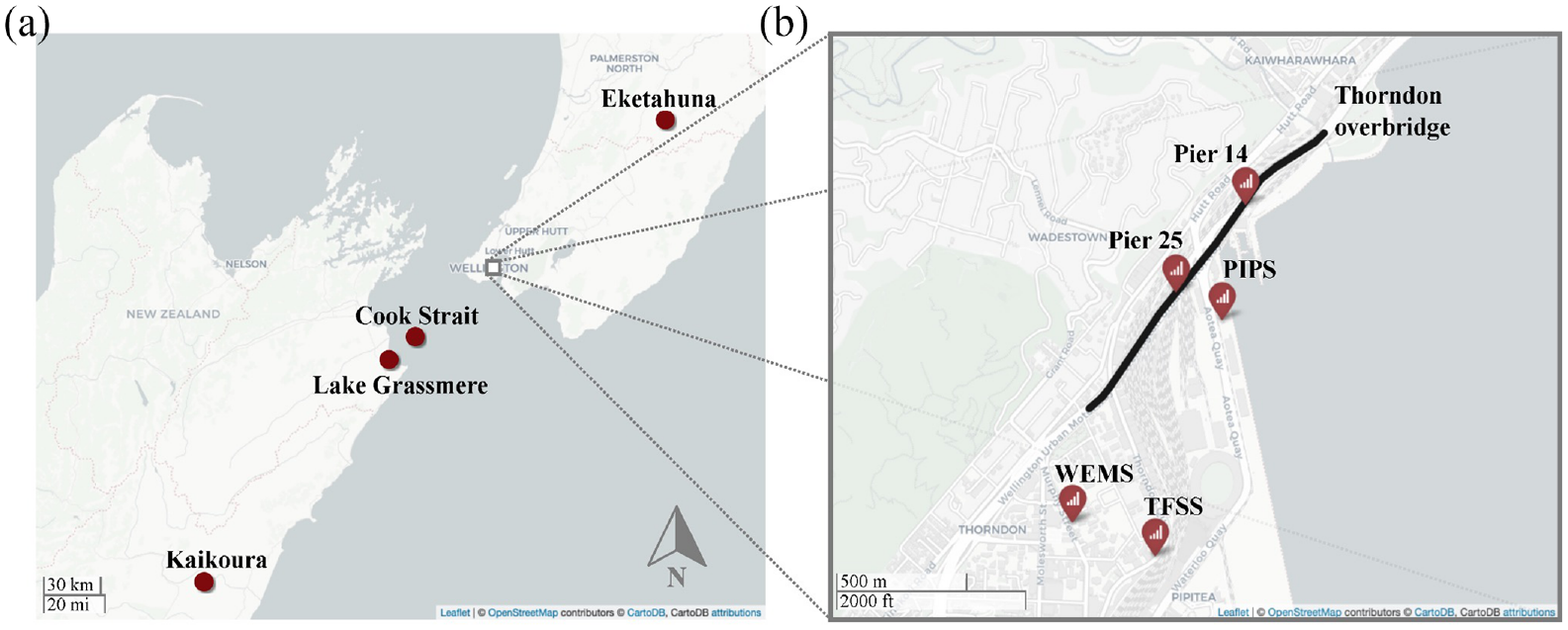
(a) The central region of New Zealand showing location of the epicenters of the earthquakes presented in this article. (b) Inset view of the Wellington Central Business District with the location of the Thorndon Overbridge and the nearby strong ground-motion stations shown with red symbols (the name of each is labeled in the figure).
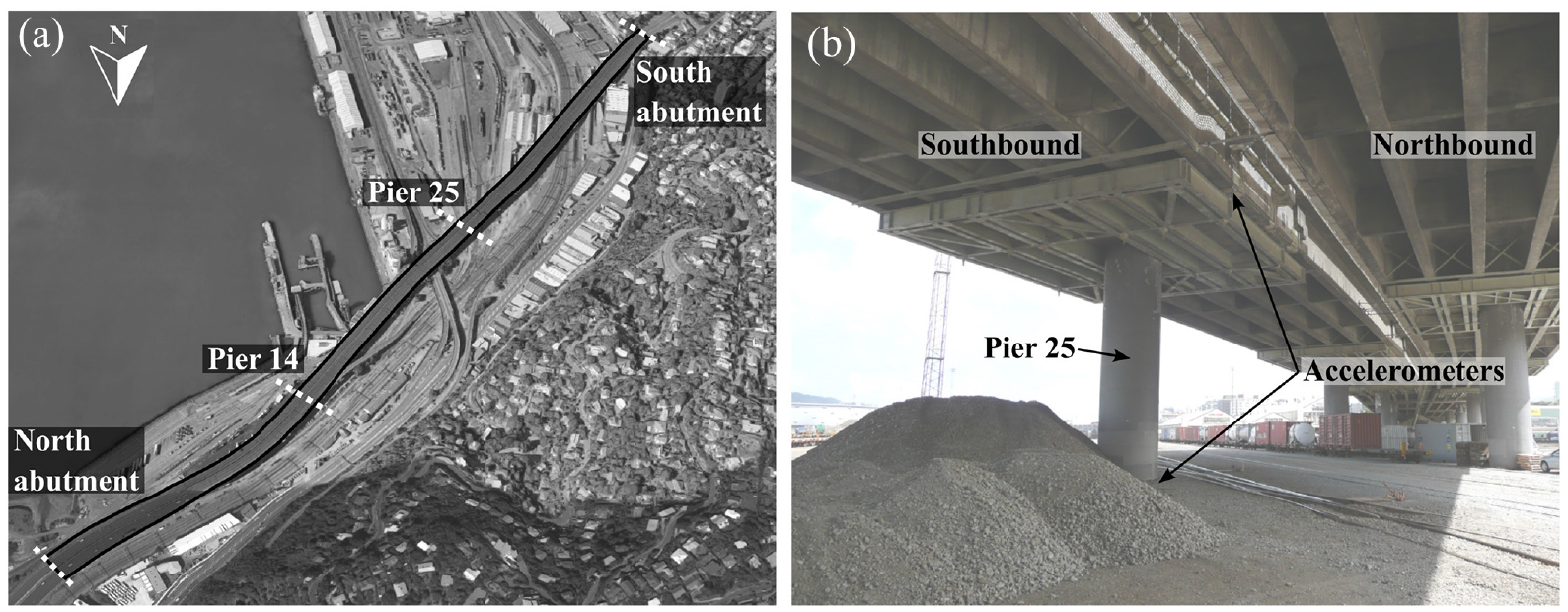
(a) Aerial view of the Thorndon Overbridge. (b) Photo of Pier 25.
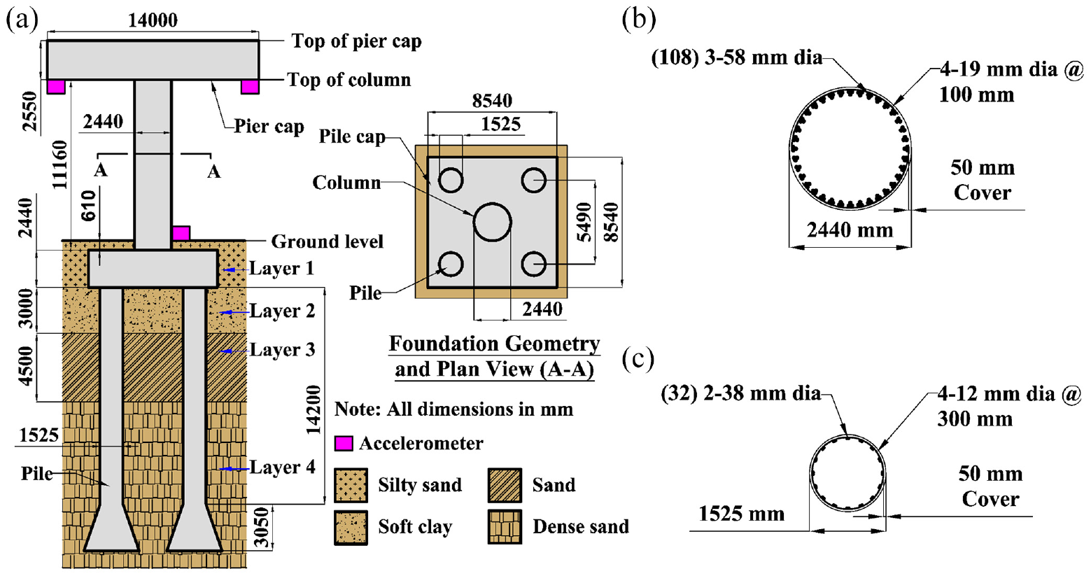
Structural and geotechnical characteristics of Pier 25 of Thorndon Overbridge. (a) Elevation view of the pier and foundation geometry and plan view from below the superstructure. (b) Cross-section details of the pier column. (c) Cross-section details of the piles.
The Thorndon Overbridge was designed using preliminary ductile standards that were introduced in the mid-1960s. To determine the base shear for design, these standards recommended multiplying the weight of the bridge using a seismic coefficient defined based on a smoothed elastic response spectrum representative of the largest horizontal component of the 1940 El Centro earthquake (refer to Figure 4) (Chapman et al., 1974). Bridges designed using these standards were assumed to have a global ductility of four when the necessary reinforcement detailing was provided and local ductility at plastic hinges potentially larger than four (Hogan et al., 2013).
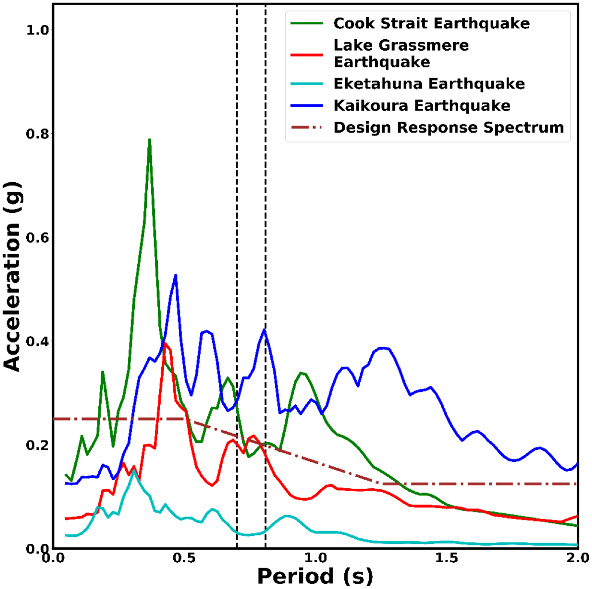
Acceleration response spectra of the free-field ground-motion records at Pier 25 of Thorndon Overbridge during the four earthquakes of interest and the elastic design response spectrum for 3% equivalent viscous damping. The vertical dashed lines show the range of the fundamental period of the bridge pier.
Seismic assessment of the Thorndon Overbridge in the 1980s suggested that there was inadequate confinement reinforcement in the lower sections of the pier columns, and in 1988, seismic strengthening was undertaken to prevent premature shear failure at the terminal points of longitudinal reinforcement. All the pier columns were jacketed with 10- to 12-mm thick steel plate to provide additional shear strength and confinement, while not contributing any additional flexural strength. The critical section for the column was at the junction of the column and pile cap, while the critical section for the pile was at the junction of the pile and pile cap. In addition, to prevent the development of any plastic hinging in the pile caps, they were retrofitted using post-tensioned side beams. A detailed description of the seismic strengthening work can be found in the work by Wood (2014).
Bridge instrumentation
A seismic monitoring system was installed in two zones in the northern and southern sections of the Thorndon Overbridge in March 2011 as part of the GeoNet Structures Instrumentation Program (Navabian, 2020; Wood, 2014). Within each zone, multiple accelerometers were installed on the superstructure of the bridge, with a single accelerometer at the ground level 50 mm from the base of the middle pier column (at Pier 25 and Pier 14 shown in Figure 1). In each zone, the typical locations of the accelerometers on the superstructure of the bridge were the east and west sides of pier cap (Figure 3), center of pier cap (on end piers of each zone), and center of the spans. The recorded response of the bridge pier in southern section (Pier 25) was considered in this study as the piers in this section of the bridge did not have any connection with the piers of the parallel bridge structure. The acceleration response recorded by all accelerometers on the superstructure of the bridge pier was similar across all events, with the data from the top of Pier 25 presented herein.
Geotechnical site characterization
The Thorndon Overbridge is constructed over reclaimed land, and a simplified representation of the soil layers and their depths at Pier 25 are summarized in Figure 3. The soil profile at Pier 25 was defined based on cone penetrometer test (CPT) soundings from a location close to the pier (30 m approximately) and information from construction drawings. At Pier 25, the upper soil layer consisted of a 3-m thick layer of silty sand with a CPT tip resistance (qc) of 8 MPa. Beneath the top surface layer was a 3-m layer of soft clay with a qc of 0.5–1 MPa throughout the layer. Below this was a 4.5-m sand layer with a qc of 6 MPa. The top sandy soil layers are prone to liquefaction under ultimate limit state loading, while liquefaction was not expected under serviceability limit state loading. The lower stratum that forms the bearing layer has a tip resistance of above 20 MPa, transitioning into very dense sands with CPT refusal.
Recorded response and dynamic characteristics
Since the installation of instrumentation, the Thorndon Overbridge has experienced three earthquakes with moderate levels of shaking and one with lower levels of shaking (for a total of four earthquakes). The location of the epicenter of each of these earthquakes is shown in Figure 1, while the characteristics of each of the earthquakes are summarized in Table 1. The Cook Strait earthquake and the Lake Grassmere earthquakes occurred on the July 21 and August 16, 2013, respectively; both were part of the Cook Strait earthquake sequence (Holden et al., 2013). The largest peak ground accelerations (PGA) in central Wellington during the Cook Strait and Lake Grassmere earthquakes were 0.26 and 0.20 g, respectively, with minor structural and infrastructure damage evident in the surrounding area following these earthquakes. The 2014 Eketahuna earthquake (Abercrombie et al., 2017) resulted in lower levels of shaking and no damage in Wellington. This event was included in this article as good-quality recordings of the ground motions at Pier 25 were captured, allowing for an assessment of the response of the pier at low excitation levels. The most recent earthquake that resulted in moderate shaking in Wellington was the 2016 Kaikōura earthquake that led to substantial damage to mid-rise to high-rise buildings and infrastructure networks in central Wellington. Even though there was damage evident across central Wellington in multiple of these events, the Thorndon Overbridge performed well with no observed structural damage. Figure 4 presents the acceleration response spectra for 3% equivalent viscous damping (the procedure followed to determine damping is discussed in section “Rayleigh damping”) for the four free-field ground motions recorded at Pier 25 and the design response spectrum (elastic design response spectrum divided by the design ductility) for 3% equivalent viscous damping used in the bridge design (Chapman et al., 1974). The acceleration demands on the bridge at its fundamental period were equal to or greater than the design demands for the Cook Strait, Lake Grassmere, and Kaikōura earthquakes. The influence of the characteristics of the response spectra is discussed in more detail in subsequent sections of this article.
Details of earthquakes experienced by Thorndon Overbridge since 2011
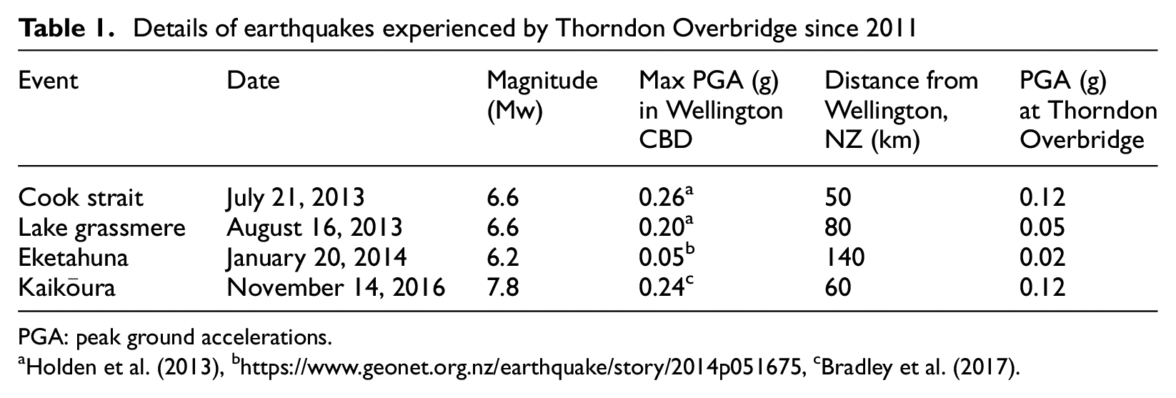
PGA: peak ground accelerations.
The fundamental period of Pier 25 in the transverse direction during each earthquake was estimated using a combination of peak picking from Fast Fourier Transformation (FFT) and peak-to-peak intervals from the acceleration time histories recorded at the top of Pier 25. Based on this approach, the fundamental period of the pier varied between 0.7 and 0.81 s across all the earthquakes. The changes in fundamental period can be explained through a comparison of the spectral accelerations for each earthquake within the range of fundamental periods shown in Figure 4. The fundamental period during each record increased with increasing spectral acceleration, suggesting that there was softening of the bridge pier system without evidence of structural damage. The fundamental period of the bridge was 0.72 s during the Cook Strait earthquake and increased to 0.78 s during the Lake Grassmere earthquake where slightly higher spectral accelerations were measured. During the Eketahuna earthquake, the significantly lower spectral accelerations meant that the system likely experienced little softening, resulting in a fundamental period estimate of 0.7 s. This suggests that the softening experienced during previous earthquakes was not permanent, likely due to the soil surrounding the foundation system regaining stiffness. The Kaikōura earthquake had the largest spectral accelerations in this period range, resulting in the largest estimated fundamental period of 0.81 s. The measured acceleration time histories at the top of Pier 25 and the corresponding acceleration response spectra are presented later in the article where they are compared with the numerical model response.
Modeling of Thorndon Overbridge
To provide a more in-depth understanding of the response of the Thorndon Overbridge, numerical models were developed based on a Nonlinear Beam on Winkler Foundation approach using the open-source structural analysis software OpenSeesPy (Zhu et al., 2018). A single-pier model was developed using recommendations from the works by New Zealand Transportation Agency (2018) and Priestley et al. (2007) to replicate the recorded response of the bridge in the transverse direction during the aforementioned earthquakes while accounting for material and soil nonlinearity. The single-pier approach was used as each span was simply supported and separated by expansion joints, meaning the piers could respond somewhat independently in the transverse direction. Modeling focused on the transverse direction as the response was significantly less in the longitudinal direction.
Model overview
A center-line modeling approach was used to represent the single-pier model, and the schematic representation of the model is presented in Figure 5. The pier cap was modeled as a single elastic beam-column element extending from the center of mass of the pier cap to the top of the column. As the pier cap had hollow regions in the upper part of its cross-section, the center of mass was only 1010 mm above the column top. Regions of the column between the bottom of the pier cap and the top of the pile cap were modeled using displacement-based distributed plasticity beam-column elements with three integration points per element. Overall, 39 elements were used along the length of the column, with finer meshing toward the bottom of the column. A convergence study was undertaken to determine the required number of elements for column, pile, and pile cap to adequately capture the response, finding a balance between the number of integration points assigned to each element and the length of each element. The piles were modeled using displacement-based distributed plasticity beam-column elements with three integration points up to 7 m below the ground surface, which is representative of the pile active length (Davies and Budhu, 1986), and elastic beam-column elements were used below this depth. Each pile was divided into 40 elements with finer meshing toward the top of the pile. A fine mesh at the bottom of column and top of pile was necessary to capture the behavior of column, pile, and soil in detail in the maximum bending moment regions, where inelastic material response was most likely to occur. To represent the pile cap cross-sectional characteristics, elastic beam-column elements with cross-sectional properties representative of the pile cap geometry were used to connect the bottom of the column and the top of each pile.
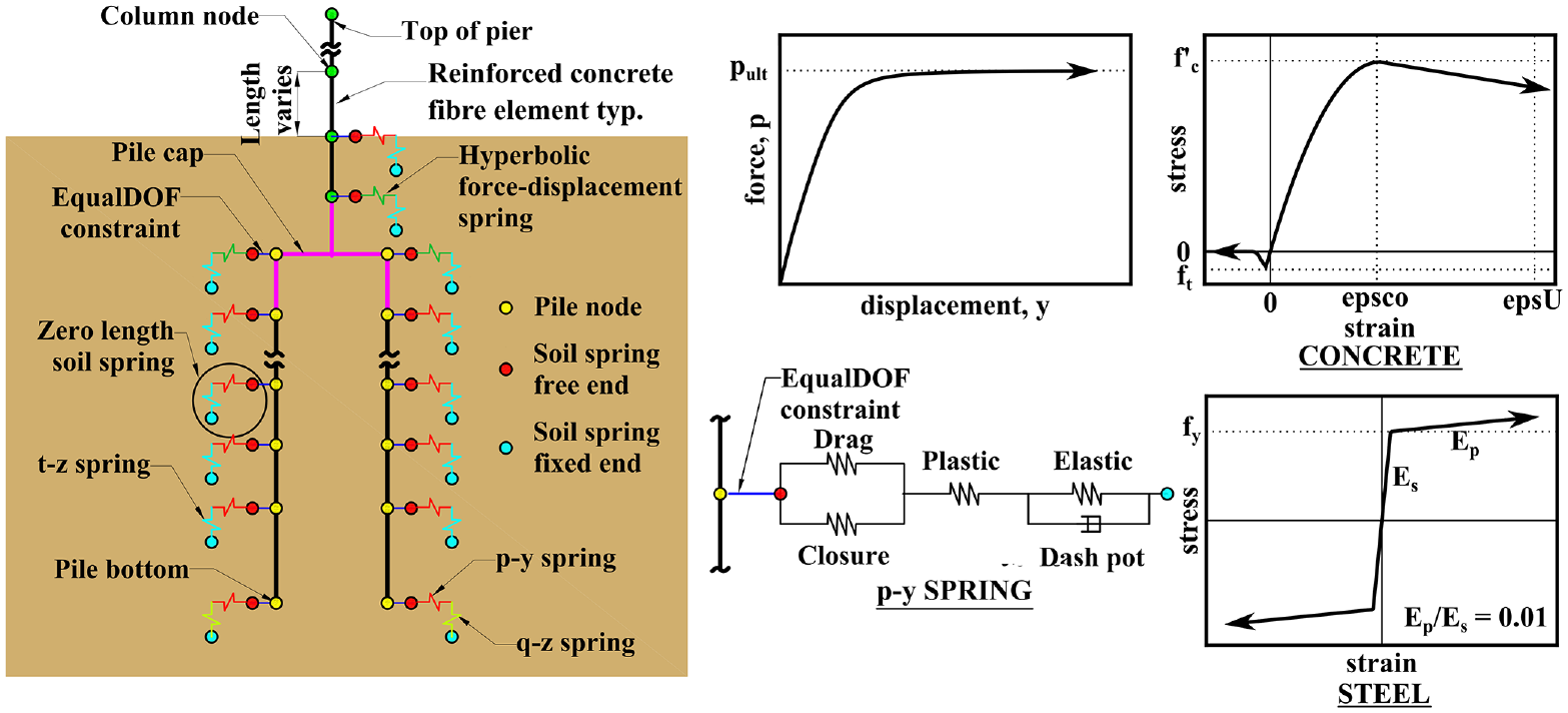
OpenSeesPy model representation for Pier 25 of Thorndon Overbridge. Element layout and schematic representations of the material models used to define the soil and structural materials.
Mass corresponding to the tributary length of a cross-section was lumped at the nodes between elements using a concrete density of 2400 kg/m3. The mass of the pier cap, which was estimated to be 375 tons (representing a column axial load ratio of 2.3%), along with its rotational mass moment of inertia was lumped at the center of mass of the pier cap. P-delta effects were considered in the modeling; however, these effects were expected to be minor given that the peak drifts experienced by the bridge were less than 1%.
The recorded free-field ground motions were used as input ground motions in the model and were applied as a uniform excitation. Using uniform excitation, the same ground-motion excitation was applied to all the fixed end nodes. Here, the fixed end nodes were present at the end of soil springs (Figure 5), and the amplification of free-field ground motion along the pile depth was ignored. Analysis focuses on the transverse response of the pier, with only the transverse component of each ground motion applied during the analysis.
Structural component modeling
To capture the nonlinear behavior of the pier, critical regions of pile and column were modeled using a fiber-based approach with cross-sectional characteristics summarized in Figure 3. Schematic representations of the concrete and steel reinforcement are provided in Figure 5. A convergence study was used to define the appropriate discretization of the fiber meshing for both column and pile sections. For each pile and column section, the core concrete fiber area was divided into 50 radial divisions with 12 circumferential divisions, and the cover concrete area was divided into 20 radial division with 16 circumferential divisions. The discretization of fiber meshing exceeded the discretization recommended from the works by Berry and Eberhard (2008) to adequately capture the response of bridge pier subjected to seismic loading, with this finer discretization needed to capture the changes in the fundamental period of the pier and the peak displacements of the structure post cracking.
Unconfined and confined concrete fibers were modeled using the Kent-Scott-Park material model with linear tension stiffening (Concrete02 in OpenSeesPy). The column and pile concrete material model properties are summarized in Table 2 with confined concrete properties defined using the Mander et al.’s (1988) model. The characteristic concrete strength (f’c) used in the numerical models was based on the as-built concrete strength measured during the construction of the bridge, accounting for aging effects using a factor of 1.5 according to Clause 5.4.2.2 from New Zealand Society for Earthquake Engineering (NZSEE, 2018) and was assigned to the unconfined regions of concrete sections. The concrete tensile strength (ft) was estimated using the approach from NZS3101 (Standards New Zealand, 2017). The tensile strength was included in the material models as this was shown to have an influence on the modeling results. Steel reinforcement fibers were modeled using a bilinear formulation with kinematic hardening, implemented using a nonlinear evolution equation (Steel01 in OpenSeesPy) with a yield strength of 430 MPa and a strain hardening ratio of 0.01. All the elastic members of the bridge were modeled using a Young’s modulus of 30.5 GPa, and the sectional properties were defined using the gross sectional properties of the members calculated based on the structural drawings. The steel casing around the pier column was not included in the modeling as these were designed to increase the shear carrying capacity of the columns without influencing the flexural characteristics (Wood, 2014).
Concrete material properties used in OpenSeesPy modeling for different column section and pile section regions
epsc0 = concrete strain at f’ c , fpcu = concrete crushing strength, epsU = concrete strain at crushing strength.
Soil modeling
Soil in the pile region of the bridge pier was modeled using nonlinear p-y, t-z, and q-z springs to capture the expected response of the system accounting for soil–structure interaction. The nonlinear cyclic load–displacement response in the lateral direction was modeled using p-y springs (shown schematically in Figure 5) with elastic, plastic, and gap components in series (Boulanger et al., 1999). The gap component consists of a nonlinear closure spring in parallel with nonlinear drag spring to represent soil drag along the side of the pile. To represent the vertical contribution of the soil to pile response, t-z and q-z springs were implemented.
The p-y soil springs for soft clay were defined using recommendations from the work by Reese and Welch (1975), with the ultimate capacity (pult) defined based on undrained shear strength derived from CPT tip resistance-based correlations (Lunne et al., 1997) with su equal to 100 kPa. The nonlinear t-z and q-z soil springs were modeled similar to p-y soil springs. The t-z and q-z soil springs for soft clay were defined using recommendations from the work by Reese and O’Neill (1987). For the soft clay, the displacement, at which 50% of pult (y50), tult (z50), and qult (Z50) was mobilized, was defined based on the pile diameter and the recommended range of strain 50 (ε50) values (0.02 used herein) from the work by Matlock (1970).
For sand layers, the p-y spring properties were based on the API recommendations (1987) and the t-z and q-z soil spring properties were based on the recommendations from Mosher (1984). CPT tip resistance-based correlations of Robertson and Campanella (1983) and Robertson (2010) were used to define the (37°) and soil unit weight (20 kN/m3), respectively, for each of the sand soil layers. The p-y, t-z, and q-z springs were based on the ultimate capacity of the p-y springs (pult), t-z springs (tult), and q-z spring (qult), and the displacement at which 50% of pult (y50) was mobilized was based on API recommendations (1987) and 50% of tult (z50) and 50% of qult (Z50) was mobilized was based on the recommendations from the work by Mosher (1984). Pult and y50 were equal to 290 kN and 3 mm, respectively, at shallower depths, with these values then increasing with depth.
The top of ground level was 1830 mm above the center of pile cap (zero level) in the model. Due the large dimensions of the pile cap, the pile cap–soil interaction in the region representing the pile cap (1220 mm above and below center of pile cap) was modeled using a hyperbolic force—displacement (HFD) relationship representative of a bridge abutment (Khalili-Tehrani et al., 2010; Shamsabadi et al., 2010). Soil properties were based on the estimates for silty sand described in the work by Shamsabadi et al. (2007). These properties were distributed across the soil springs in the pile cap region based on the tributary area of each spring. Soil above the top of pile cap was modeled similar to the soil in the pile regions using nonlinear p-y and t-z springs based on the cross-sectional characteristics of pier column.
Rayleigh damping
Equivalent viscous damping of the bridge during the earthquakes was estimated following the method from the work by Chopra (1995) based on the acceleration response spectra of the recorded free-field ground motions, the estimated fundamental periods of the pier, and peak acceleration values from the acceleration time histories recorded at the top of the Pier 25. Initially, the acceleration response spectra of the free-field ground motion recorded during Cook Strait earthquake for various equivalent viscous damping values were obtained. The acceleration values corresponding to the bridge fundamental period from different acceleration response spectra were compared against the peak acceleration recorded at the top of Pier 25. The peak acceleration value matched well with the value corresponding to an acceleration response spectrum of 3% equivalent viscous damping. This process was repeated for other earthquakes. This was consistent with the observations made by McCallen and Romstad (1994), Atkins and Wilson (2000), and Narita and Yokoyama (1991), where they found using an equivalent viscous damping value of less than 5% predicted the peak accelerations of the bridges in each study.
Considering the equivalent viscous damping calculated using the method described above as an upper bound value for total damping (including hysteretic damping), a constant Rayleigh damping of 2% was provided to the numerical model for all the earthquakes. The Rayleigh damping value was based on the validation of numerical models and recommendations from the works by Atkins and Wilson (2000) and Chigullapally et al. (2022). The target frequencies used for defining the Rayleigh damping parameters were the natural frequency and three times the natural frequency for each model.
Modeling results
Numerical modeling results were compared to the recorded data by applying the recorded free-field ground motions as input ground motions into the model and key parameters were assessed to evaluate the model performance. The model was later used to conduct a sensitivity study to identify the parameters controlling the dynamic response of the bridge pier during the Cook Strait earthquake and to assess the influence of the input motion using ground-motion recordings taken from different strong-motion stations during the same earthquake.
Modeled response of bridge pier during multiple earthquakes
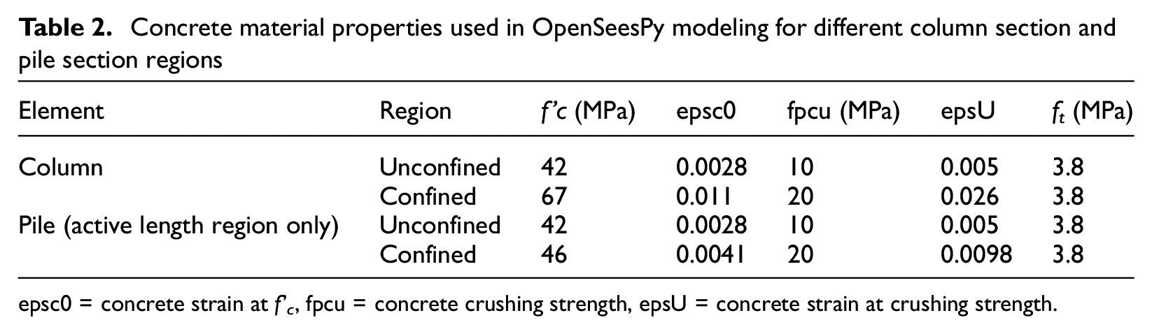
The numerical model and recorded response at the top of Pier 25 during multiple earthquakes were compared using displacement time histories (Figure 6), acceleration response spectra (Figure 7), and peak displacement, acceleration, and fundamental period values (Table 3). All ground motions were applied in chronological order to the model to ensure that damage progression and residual deformations in the system were retained following each earthquake, thereby influencing the response in subsequent earthquakes. The model was able to represent the observed changes in the recorded bridge pier response metrics from one record to the next.
Comparison between recorded and modeled displacement time histories at the top of Pier 25 during the (a) Cook Strait, (b) Lake Grassmere, (c) Eketahuna, and (d) Kaikōura earthquakes.
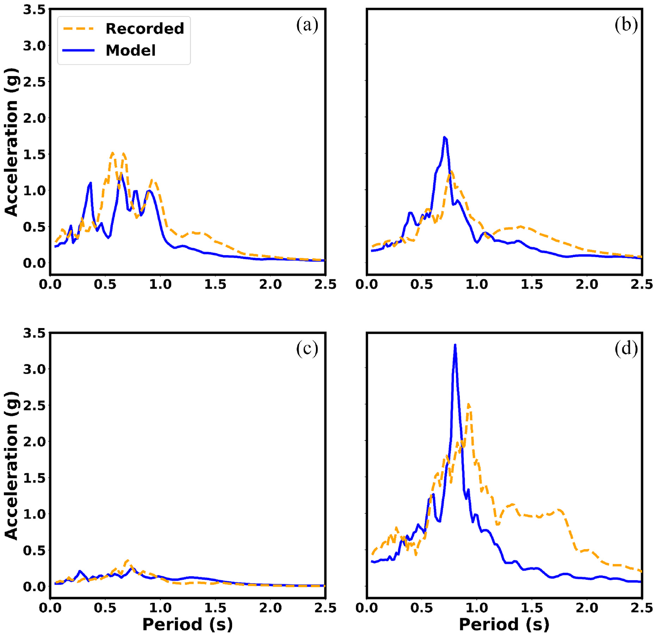
Comparison between recorded and modeled acceleration response spectra (from the acceleration time histories) at the top of Pier 25 during the (a) Cook Strait, (b) Lake Grassmere, (c) Eketahuna, and (d) Kaikōura earthquakes.
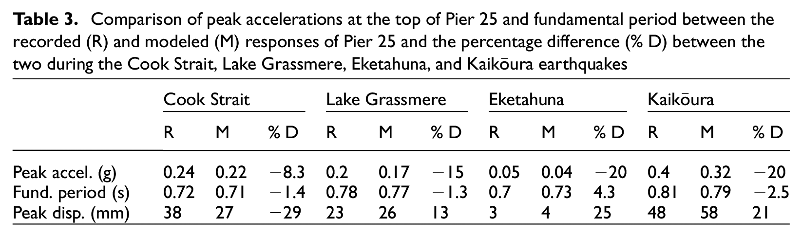
Comparison of peak accelerations at the top of Pier 25 and fundamental period between the recorded (R) and modeled (M) responses of Pier 25 and the percentage difference (% D) between the two during the Cook Strait, Lake Grassmere, Eketahuna, and Kaikōura earthquakes
The acceleration response spectra from the numerical and recorded time histories were similar for all the earthquakes, and the numerical models were able to represent the variation in the periods at which peak spectral accelerations occurred. The fundamental period of the bridge (estimated using the same approach described previously for the recorded response) and the variation in the fundamental period between the earthquakes showed that the models were able to capture the system softening. Maximum errors in peak acceleration and fundamental period across all ground motions of 20% and 5% during the Kaikōura earthquake, respectively. The discrepancies between numerical model and recorded response could be due to the close proximity of the accelerometer to the bridge piers, meaning the recorded acceleration records may have been affected by the response of the bridge pier itself during the earthquakes.
The cracking moment of the pier column was equal to 3000 and 3300 kNm, respectively. Numerical modeling suggested that the pier column first cracked during the Cook Strait earthquake, while the piles first cracked during the Kaikōura earthquake. Therefore, the fundamental period of the bridge pier during the first three earthquakes was influenced by the cracked pier column, while the period of the bridge pier during the Kaikōura Earthquake was representative of both cracked pier column and piles. The moment curvature at the base of the pier column during the Kaikōura earthquake is presented in Figure 8. During the Kaikōura earthquake, the maximum curvature demands experienced by the pier column and piles were 1.1 and 0.9 rad/km, respectively, with the softening of the moment curvature response clearly visible in Figure 8.
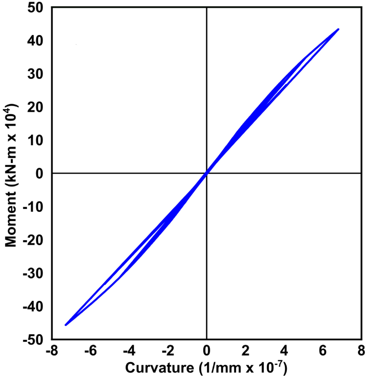
Modeled moment curvature at the base of the pier column during the Kaikōura earthquake.
The force–displacement response of the HFD spring at the pile cap level during the Kaikōura earthquake is presented in Figure 9, showing softening and dissipation of energy through hysteretic response. This was the only earthquake where soil nonlinearity was evident. Based on maximum flexural demands in the piles and columns from the numerical model, modeling suggests that the softening of the model during the sequential earthquakes was a result of concrete cracking and soil nonlinearity rather than any significant structural damage.
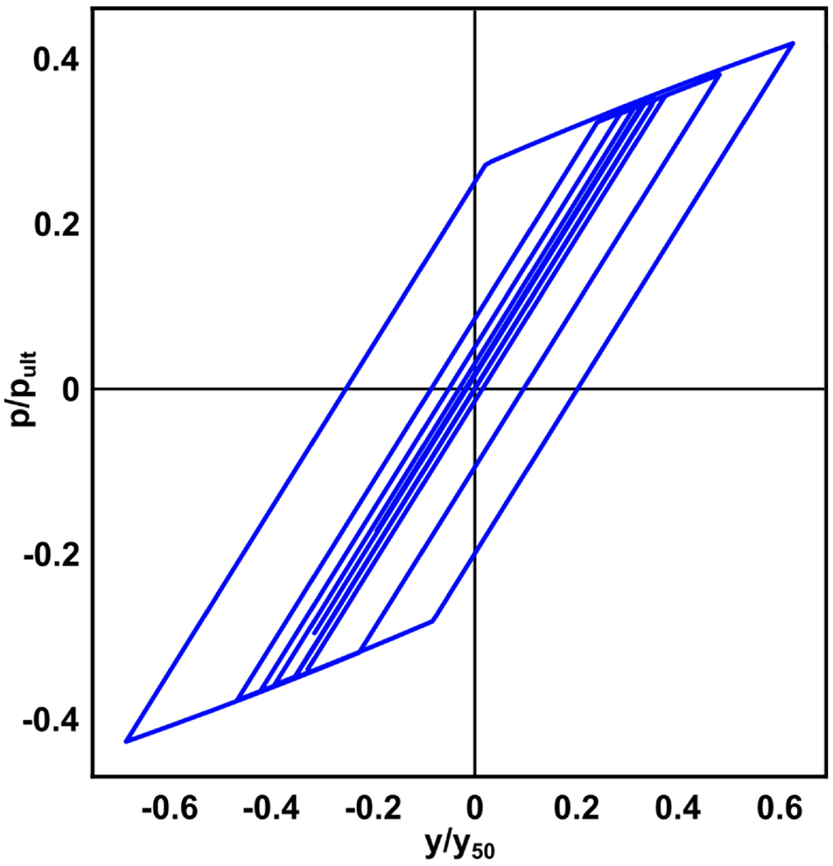
Modeled force–displacement response of the HFD spring at pile cap level during the Kaikōura earthquake.
Sensitivity analysis of material properties
To evaluate the influence of key material properties on the dynamic response of the Thorndon Overbridge, a sensitivity analysis was conducted using the Cook Strait earthquake record at Pier 25 as the input motion. This motion was used for this study as it was the first of the earthquakes in this series and thus avoids the compounding uncertainties associated with modeling the sequential earthquakes. The sensitivity of the model was assessed using the following dynamic response metrics:
Peak superstructure acceleration;
Peak superstructure displacement;
Fundamental period;
Maximum pier bending moment;
Peak superstructure spectral acceleration.
The material parameters assessed in the sensitivity analysis included the concrete compressive strength, pult, and y50 values of the p-y springs, and force and displacement values of the HFD springs in the pile cap region. The concrete compressive strength was varied from 70% to 125% of the reference value, with the upper bound defined in some regions of the bridge piers and beams based on core sample testing and the lower bound representative of the concrete strength at the time of construction. The key concrete properties that will be influencing the response are the Young’s modulus and the tensile strength of the concrete, both of which are a direct function of f’c. This equates to variation of these properties from 84% to 112%. For the top soil layer (Layer 1), the force and displacement values of the HFD springs in the pile cap region were varied between 50% and 200%. The same percentages were used for the p-y springs applied toward the base of the column. For the soil layers along the length of the piles (Layers 2, 3, and 4), the pult value was varied directly, while the y50 value was modified by varying the ε50 value. The sensitivity to both these parameters was assessed using 50%–200% of the reference value (Building Seismic Safety Council (BSSC), 1997).
The sensitivity analysis demonstrated that concrete properties and the top soil layer properties had the most influence on the dynamic response of the system. Figure 10 summarizes the results of the sensitivity analysis across the dynamic response metrics for the concrete compressive strength and pult of the top soil layer. Across all the soil layers, only the soil in the regions surrounding the column and pile cap influenced the dynamic response of the bridge pier. Results for the pult and y50 values of the bottom three soil layers (Layers 2, 3 and 4) are not included in Figure 10 as there was a variation of less than 4% in peak superstructure acceleration, peak superstructure spectral acceleration, and peak superstructure displacement values, and no variation in fundamental period and maximum pier bending moment values.
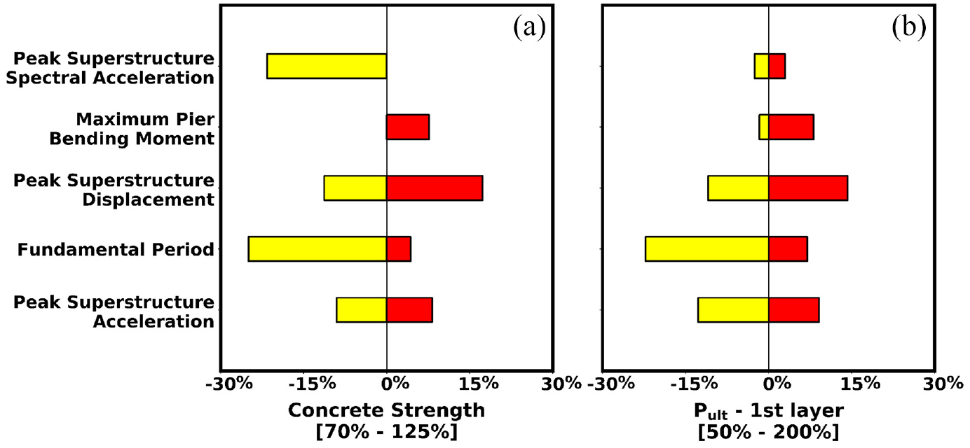
Sensitivity of Pier 25 dynamic response metrics to variation in (a) concrete strength (and associated properties) and (b) pult of top soil layer for the Cook Strait earthquake record.
Modifying the concrete properties had a significant influence on all the dynamic response metrics, with a variation of up to 25% in the strength range considered. For an increase in the concrete strength, the stiffness of the bridge pier increased, reducing the values of all the parameter considered, except for peak superstructure spectral acceleration. When concrete strength was reduced, the flexibility of the bridge pier increased, increasing the values of all the parameter considered, except maximum pier bending moment which reduced by 3%.
Modifying the pult and y50 values in the top soil layer inversely impacted changes in the dynamic response metrics (e.g. increasing pult and decreasing y50 values had similar effect) but resulted in the same net changes, so only the pult plot is included in Figure 10b. When lower-bound values of pult values of top soil layer (or upper bound values of y50 values of top soil layer) were considered, there was an increment of up to 22% in all the parameters considered due to increased flexibility of the bridge pier. When upper-bound values of pult of top soil layer (or lower-bound values of y50 values of top soil layer) were considered, there was a decrease in up to 15% in all the parameters considered due to increased stiffness of the bridge pier as the soil surrounding the pile cap has increased stiffness and strength. The sensitivity analysis showed the soil strength and stiffness of the near-surface soil layers has a significant influence on overall response. This was primarily due to the large dimensions and stiffness of the pile cap, which also meant that the soil below in the pile regions was not significantly engaged during the excitation.
Ground-motion station selection
The influence of the variability of the recorded input motions on the estimated response was evaluated using ground-motion recordings taken from different strong-motion stations in the vicinity of the bridge during the same event. Post-earthquake assessments (in the absence of instrumentation on a structure) typically make use of the free-field ground motions recorded from the nearby ground-motion stations, and the general recommendations for ground motion station selection for assessments focus on spatial distance of the structure and station to the epicenter and the local site conditions (American Society of Civil Engineers (ASCE), 2021; Standards New Zealand, 2004). The efficacy of this approach is evaluated here for the Thorndon Overbridge.
In this study, a total of five free-field ground-motion recording stations in the vicinity of the Thorndon Overbridge were used to evaluate the influence of the spatial variability of ground-motion recordings on the calculated structure response. Pier 25 of the bridge was taken as the reference station, and free-field ground motion recordings for the earthquakes studied were obtained from Pier 14 of the Thorndon Overbridge (400 m from Pier 25), aotea quay pipitea (PIPS) (150 m from Pier 25), Wellington thorndon fire station (TFSS) (1 km from Pier 25), and Wellington emergency management office (WEMS) (1 km from Pier 25) ground-motion recording stations. The location of these stations in relation to Pier 25 is shown in Figure 1. The Eketahuna earthquake was not considered in this discussion as the TFSS station did not trigger a recording during this earthquake due to shaking not exceed the threshold recording value. Each recording station was classified as site class of D according to the New Zealand standard for seismic structural design actions (NZS1170.5) (Standards New Zealand, 2004), with a site period (fundamental period of the soil profile above bedrock) greater than 0.6 s (Table 4). All recording stations were also site class D according to ASCE/SEI 7-22 (ASCE, 2021), with VS30 values between 180 and 360 m/s. As the orientation of the horizontal components at each recording location was not same, the recorded motions were rotated to align with the transverse axis of the bridge pier based on the relative orientation between each location and Pier 25. All ground motions were applied in the same sequential order as previously discussed to ensure that damage progression and residual deformations in the system were captured for each earthquake (the removal of the Eketahuna earthquake was not expected to influence these results given the low-intensity excitations from this event).
Time-averaged shear wave velocity over the top 30 m (VS30), site period (T0), and site class of the ground-motion recording locations in the vicinity of the Thorndon Overbridge
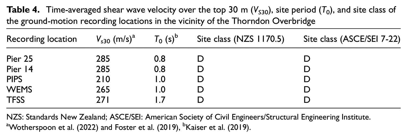
NZS: Standards New Zealand; ASCE/SEI: American Society of Civil Engineers/Structural Engineering Institute.
The acceleration response spectra of the free-field ground motions during the Cook Strait, Lake Grassmere, and Kaikōura earthquakes across all ground motion stations are presented in Figure 11. The response spectra obtained from different ground-motion stations during each earthquake had different spectral shapes, peak spectral acceleration values, and spectral periods. This variation is most likely due to the influence of local site conditions on the recorded free-field ground motions, which highlights the importance of selecting the appropriate input motion. In particular, large discrepancies in structural response would be expected in cases where different ground-motion recordings have different spectral acceleration values at the fundamental period of the structure. This variation in input spectral acceleration can be quite pronounced as observed during the Lake Grassmere earthquake at PIPS and WEMS stations in which there was an approximate threefold amplification in spectral acceleration at the bridge fundamental period as shown in Figure 11b.
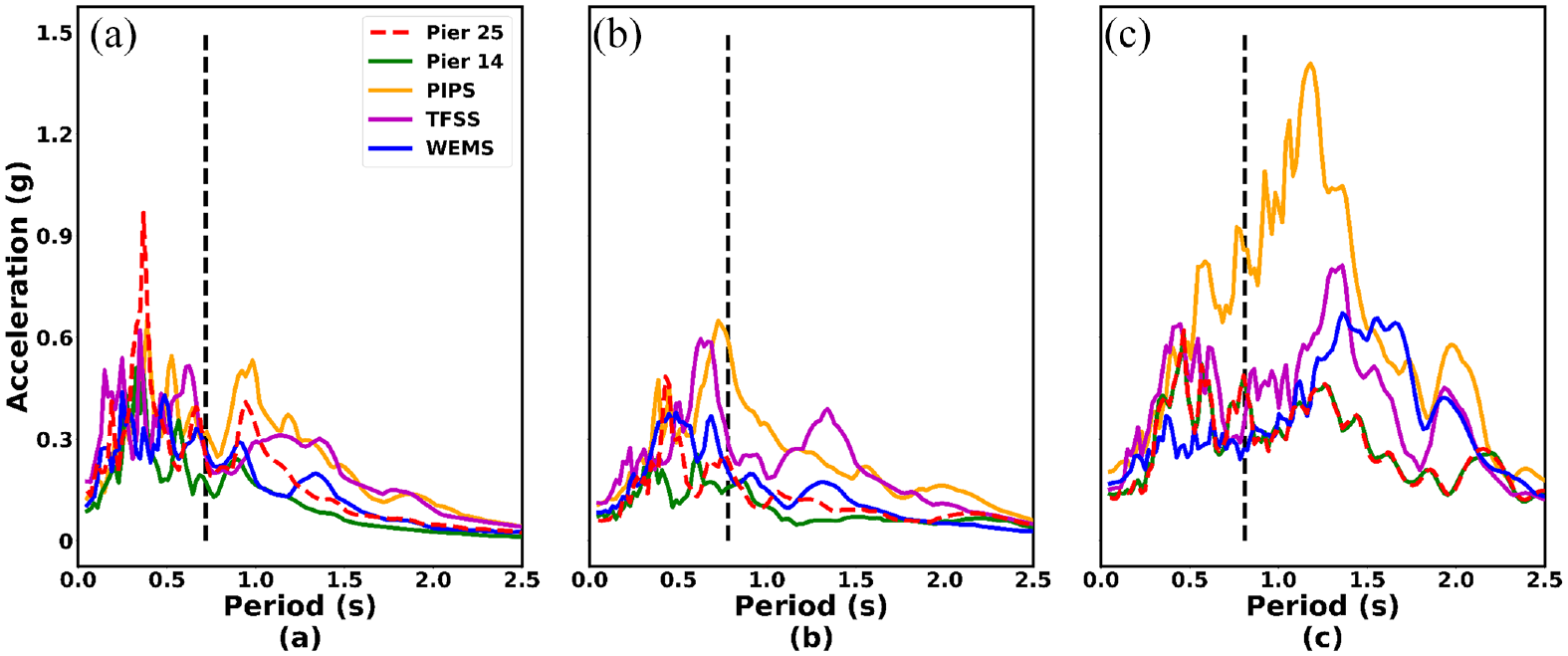
Comparison of acceleration response spectra of the input ground-motion records recorded at multiple ground-motion recording stations during the (a) Cook Strait, (b) Lake Grassmere, and (c) Kaikōura earthquakes along with the estimated fundamental periods (from recorded response) of the bridge pier during these earthquakes (shown by vertical black dashed lines in each figure).
The same dynamic response metrics discussed in section “Sensitivity analysis of material properties” are shown in Figure 12 across all the ground motions recorded at each strong-motion recording station. The variation in these dynamic response metrics was not significant during the Cook Strait earthquake, while the differences were substantial during the Lake Grassmere and Kaikōura earthquakes. This was due to each recording having similar spectral shape and accelerations (Figure 11) at the bridge fundamental period for the Cook Strait earthquake, while the spectral shapes and accelerations were significantly different during the other two earthquakes. The ratio of the response values recorded at the top of Pier 25 using input motions from the different ground-motion stations to the response values recorded at the top of Pier 25 using the input motions recorded at the base of Pier 25, varied between 1 and 1.1 for fundamental period, between 0.35 and 4.5 for peak superstructure spectral accelerations, between 0.5 and 2.6 for peak superstructure acceleration, peak superstructure displacements, and maximum pier bending moment values. The lower bound of the ratios was measured when using the WEMS recording from the Kaikōura earthquake due to low spectral accelerations at the fundamental period of the bridge pier. The upper bound of the ratios was measured when using the PIPS recording from the Lake Grassmere earthquake due to the fundamental period of structure being closer to the period corresponding to the peak acceleration of the free-field ground-motion acceleration response spectrum from PIPS. It should be noted that although the PIPS station is only 150 m away from Pier 25, the largest differences were recorded at this station, likely a result of the softer near-surface soil deposits. The amount of variability in the recorded response parameters across all the ground motions evaluated highlights the difficulties involved in the back analysis of the response of structures following events when ground-motion stations close to the structure and from the same soil site class are selected.
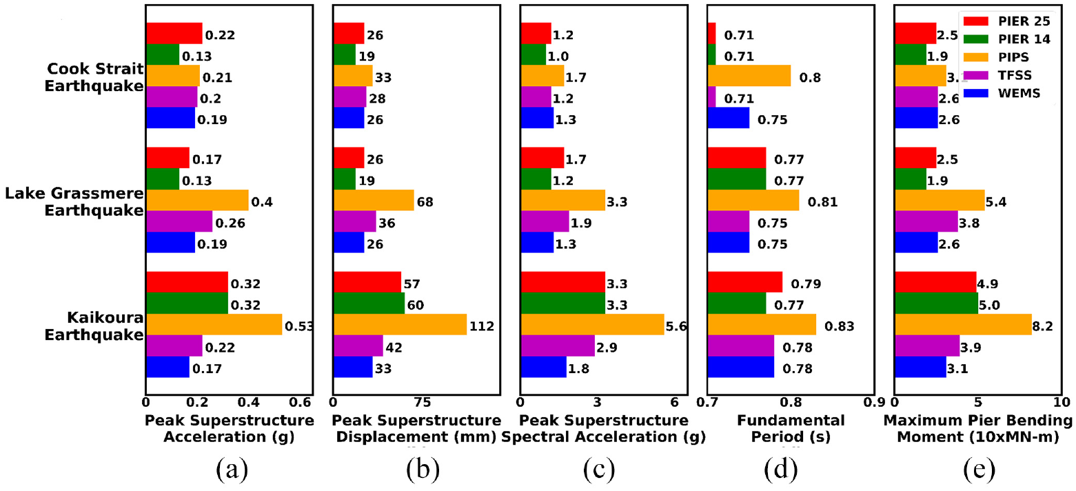
Comparison of (a) peak superstructure accelerations, (b) peak superstructure displacements at the top of Pier 25, (c) peak superstructure spectral accelerations from the acceleration response spectra of response at the top of Pier 25, (d) fundamental periods of Pier 25, and (e) maximum pier bending moment under the free-field ground motions recorded at Pier 25, Pier 14, PIPS, TFSS, and WEMS ground-motion stations during Cook Strait, Lake Grassmere, and Kaikōura earthquakes.
Conclusion
The seismic monitoring system installed on Thorndon Overbridge recorded the strong-motion response during multiple earthquakes. This recorded data were analyzed and further used to validate the numerical models developed in OpenSeesPy using a p-y spring foundation modeling approach. Based on the analysis of the recorded data and numerical modeling results, the following conclusions can be drawn:
Thorndon Overbridge bridge experienced little damage during the earthquakes studied; however, analysis of the recorded responses showed the fundamental period of the bridge varied by up to 15% across these earthquakes, highlighting the softening that could develop within the system prior to the onset of any significant structural damage.
Numerical models of a single-bridge pier developed using existing p-y curves were able to represent the observed changes in the recorded bridge pier response metrics from one record to the next and suggested that system softening was primarily due to nonlinear soil response and concrete cracking.
A sensitivity study performed showed the response of the bridge was most sensitive to the upper soil layers, reinforcing the need for good characterization of near-surface soil profile.
The sensitivity of bridge pier response due to input ground motion (between 100% and 160%) was significantly higher than the material sensitivity (less than 30%), highlighting that, in addition to uncertainties in material properties, the uncertainty in the ground motion should be considered when performing back analysis of bridge piers subjected to earthquakes when ground-motion recordings at the location of the structure are not available.
Footnotes
Acknowledgements
The authors thank the financial support of the QuakeCoRE, a New Zealand center of research excellence in earthquake resilience. They also thank the onsite logistical support of GNS Science and Dr John Wood for his role in facilitating the development of this project.
Declaration of conflicting interests
The author(s) declared no potential conflicts of interest with respect to the research, authorship, and/or publication of this article.
Funding
The author(s) disclosed receipt of the following financial support for the research, authorship, and/or publication of this article: This is QuakeCoRE publication number 0719.