
Abstract
This study presents an active flow control device for underwater applications inspired by the dermal papillae muscles of the octopus, which allow for adaptive skin texture changes in response to flow conditions. This device can deploy vortex generators (VGs) on demand in response to changes in flow conditions, thanks to embedded twisted spiral artificial muscles. The device was tested in a rectangular water channel on a hydrofoil with NASA Langley Research Centre LS (1)-0417 GA(W)-1 geometry, at Reynolds numbers of 100,000 and 120,000, while lift and drag were measured. Results demonstrated that the VGs produced an increase in lift coefficient (CL) of 25%–30% and reduction of drag by 8%–10% at high angles of attack (α), compared with a clean hydrofoil. The active flow control device ensures timely VG deployment, closely matching the peak performance of static devices across the tested α’s (i.e., 0°–24°). The on-demand deployment of the active flow control device was facilitated by an
Introduction
Underwater vehicles can be subjected to hydrodynamic stall and flow separation, especially when operating at high angles of attack (α).1,2 Hydrodynamic stall occurs when flow separates from surfaces due to adverse pressure gradient at high incidence angles. The nature of the stall can either be dynamic or static. Dynamic stall results from flow separation due to rapid change in the lifting surface.3–5 This results in the formation of vortex cores at the leading edge of the body which grow and move over the surface and eventually shed from the surface at the trailing edge, thereby causing a sudden drop in lift and an increase in drag. Under steady conditions, static stall is also possible when the angle of attack is gradually varied, resulting in the detachment of the boundary layer from the leading edge of the surface at a critical level of incidence angle.6,7
Stalls are undesirable because turbulence and pressure fluctuations associated with stalls can result in structural damage. It can also result in accidents due to loss of control and maneuverability.
Vortex generators (VGs) have been widely used to mitigate stall problems in aerial, ground, and underwater vehicles.8–12 VGs are small protrusions that are usually placed on the incoming flow-side of wings to create turbulence at the critical point of flow separation. When this happens, more momentum is added to the separated flows, thereby re-energizing the boundary layer and causing flow reattachment to the surface. Depending on the applications, VGs can be fabricated in different shapes such as plow, shielded plow, triangular plow, wedge, vane, wing, dorsal fin, dome, shielded sink, etc. 13 The choice of VGs’ geometry, size, and positioning usually depends on the flow conditions and geometry of the wing where VGs are attached. The use of VGs on lifting surfaces has been extensively studied over the past decades. Rostamzadeh-Renani et al. 1 utilized a computational fluid dynamics-based approach to study the effect of VGs on the hydrodynamic performance of a DARPA SUBOFF submarine, and the outcome showed a fivefold increase in the lift coefficient (CL) in the reverse direction, considering an optimal VGs geometry and configuration during emergency rise condition. Micro VGs have also been utilized to control instability resulting from attached cavitation in fluid machinery. Che et al. 9 and Kundu 10 studied the effect of VGs on the performance of an S1210 hydrofoil, commonly used in tidal current turbine blades. The CL was found to increase by 17% using counter-rotating VGs, while the stall was delayed by 2°. Naeini et al. 14 studied the effect of bioinspired needle-shaped VGs on the aerodynamic performance of a double-delta wing. The effect of the VGs on time-averaged vortical flows was compared with the clean wing model, and the outcome showed an increase in the flow structure of the double-delta wing, which was due to the VGs generating and delaying vortex breakdown on the wing. Kadivar et al. 15 studied the effect of hemispherical VGs on the control of transient cavitation on a hydrofoil and found that, thanks to VGs, the unstable characteristics of the cavity structures were reduced, as well as the pressure pulsation close to the wake region of the hydrofoil.
VGs are usually designed as passive devices. However, a passive design does not allow to achieve flow controls for changing flow conditions. A dynamic change of the position and/or geometry can in fact enable VGs to adapt to the stochastic nature of flow conditions. Studies have shown that positioning VGs too close to the leading edge of a wing can result in premature turbulence, increase in skin friction drag, and possible reduction in lift generated at lower α. 16 Conversely, when VGs are placed too far away from the leading edge, the flow can separate even before reaching the VGs. Palanivendhan et al. 17 simulated different VG configurations in terms of variation in orientation with respect to the leading edge, spanwise distance between VGs, and number of VGs used. The best performing configuration resulted in a 12%–15% in drag reduction. After the introduction of VGs for flow control in 1947, 18 the literature of aerospace and marine engineering is rich in scientific contributions focused on testing different VG configurations, layouts, and geometries for different lifting surfaces. Some of the literature works include, but are not limited to refs.10,19–23
Active VGs, able to be deployed on demand, have been proposed to overcome the limitations of static VGs in terms of active/adaptive flow control.24–30 As the name implies, active VGs can be adjusted or controlled in real time to optimize their performance based on current aerodynamic or hydrodynamic requirements with the help of external actuation systems. These actuation systems can rely on hydraulic actuators, 31 shape memory actuators,26,32,33 or plasma actuators. 30 While some of these solutions have proven to be promising, they are characterized by several limitations in terms of cost, portability, and hysteretic behavior. To address the limitations of current actuation systems used for active VGs, we recently proposed deployable VGs powered by twisted spiral artificial muscles (TSAMs). 34 TSAMs are manufactured from inexpensive materials such as polymer fishing lines and copper wires, shaped into a flat Archimedean spiral.35,36 TSAMs exhibit an out-of-plane vertical displacement, achieving a reversible extension of >2000% strain when electrothermally actuated with an input voltage of 0.2 V/cm for a few seconds. In this recent study, 34 TSAMs were used to deploy VGs on demand to match the best-performing configurations at different α and Reynolds numbers. The deployable VGs were tested on a NASA Langley Research Center LS (1)-0417 GA(W)-1 airfoil model using a wind tunnel. Our results showed a significant increase in CL and delay in the onset of stall.
In this article, we adapt our previous technology to underwater applications by embedding VGs deployed by TSAMs into a hydrofoil. Additionally, flow visualization was conducted to observe the influence of the VGs in delaying separation, while drag analysis was done to have an insight into the drag penalty induced by the presence of the VGs.
Our technology is inspired by the dermal papillae muscles of an octopus, which enable it to adapt its skin texture to changes in flow conditions.38,39 Figure 1A, B depicts an octopus performing skin texture change by actuating papillae muscles, while Figure 1D, E depicts the vertical displacement of two VGs upon electrothermal actuation of a single TSAM (Fig. 1E).

This study demonstrates a portable active flow control device which is submersible, thereby making it suitable for underwater applications. The device was able to match the peak performance of static flow control devices at each angle of attack tested. Specifically, VGs deployed on demand by TSAMs produced 25%–30% increase in CL and 8%–10% drag reduction at high angles of attack, compared with the clean hydrofoil.
Materials and Methods
Information related to the TSAM manufacturing, the hydrofoil and VG design and fabrication, flow visualization method, experimental setup, experimental error, and uncertainty quantification are presented in the supplementary section of this article. The TSAM parameters are listed in Table 1.
Parameters of TSAMs
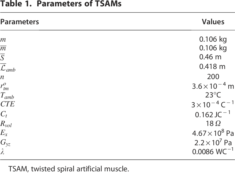
TSAM, twisted spiral artificial muscle.
Fabrication of the active flow control device and control method
The active flow control device consists of double rows of four TSAMs arranged across the span of the hydrofoil at specified distance from the leading edge (see Fig. 2A, B). Each TSAM has two VGs mounted on the top spiral, constituting to a total of 16 VGs mounted on both rows. The TSAMs with VGs were mounted on a rectangular printed circuit board (PCB) designed in-house and measuring 203.2 × 46 × 2.47 mm. The board was then inserted into the hydrofoil detachable nose, as shown in Figure 2A. TSAMs are actuated using a DC power supply. Varying the voltage supply is essential to the position/temperature tracking of the TSAM. This has been achieved by transistor-switching incorporated microcontroller signals.
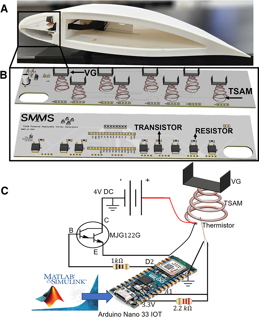
Each TSAM is actuated using a Darlington pair Negative-Positive-Negative (NPN) transistor. The base of the transistor is controlled through a microcontroller-connected pulse width modulation (PWM) signal. A 
The thermistor temperature measurement obtained from Equation 1 is fed back to the controller. Then, the temperature was converted to static height using our previous model equations.
36
The static height 

Here,
This height
VG configurations
Seven different static configurations were first tested by switching VG heights of 2 and 4 mm between the two rows. The configurations that best enhance the hydrofoil’s hydrodynamic performance by delaying stall and increasing lift were then selected to be reproduced by the active flow control device (see Supplementary Table S2 in Supplementary Data for the VG configurations definition as adopted in this study).
Results and Discussion
Effect of static VGs on the hydrodynamic performance of the hydrofoil
The performance of a hydrofoil is usually characterized by the lift and drag coefficients, as well as the lift-to-drag ratio.
42
When VGs are properly utilized on hydrofoils, it helps suppress the boundary layer separation by generating vortices at the point of separation. As a result, an increase in lift coefficient is observed compared with hydrofoils without VGs. However, the introduction of VGs can slightly increase the drag force and, as a consequence, result in a slight decrease in lift force at lower angles of attack.
43
This can be attributed to the interruption of laminar flows observed at lower angles of attack by the VGs. The lift and drag coefficients can be related to the hydrofoil geometry and flow conditions by the following relations:


In this study, seven different VG configurations were tested (see Table S2 in the supplementary document) along with the clean hydrofoil, while the corresponding lift and drag coefficients were calculated using Equations 4 and 5. Figure 3A depicts the plots for the coefficients of lift versus the angles of attack at Re = 100,000. As expected, the coefficient of lift increased with increase in α for each configuration up to a critical angle of attack, where the onset of stall was noticed for each configuration. At Re = 100,000, the two best-performing configurations in terms of lift generation were VG1 and VG2. These two configurations generated more lift between 10° and 16° for VG1, while VG2 continued generating more lift till 18° before the advent of stall. VG1 stalled at 20°, while VG2 stalled at 22°. VG3 outperformed other VG configurations in terms of lift generation at 20°. VG4, VG6, and VG7 all stalled at 24°, thereby outperforming other configurations in terms of stall delay. Similar trends were also observed at Re = 120,000 (see Fig. 3B). Both VG1 and VG2 also outperformed other VG configurations in terms of lift generation between 0° and 16°. However, early onset of stall occurred with these configurations at 18° and 20°, respectively. VG4, VG6, and VG7 all stalled at 24°, giving the best performance in terms stall delays and lift generation at higher angles of attack. The best performing configuration cannot be directly attributed to the single or double rows of VGs based on the outcome of the lift coefficient analysis. Although double rows of VGs have been reported to increase wing performance,44,45 the parasitic drag resulting from the VGs at low angles of attack can also reduce the performance of the hydrofoil. Hence, in this study, there is some sort of balance in terms of performance between the single and double rows of VGs based on the analysis of the lift coefficient. Drag analysis was conducted to further understand the impact of the VGs on the performance of the wing.

Influence of static VGs on the performance of the hydrofoils.
As depicted in Figure 3C, D, the drag coefficients of the double-row VGs were higher than that of single-row VGs, which is in agreement with previous studies on VG layout.11,46,47 As shown in Figure 3C, D, the drag coefficients for the clean hydrofoil were relatively low at Re = 100,000 and 120,000 between α = 0° and 16°, compared with other configurations. However, at higher angles of attack, the drag coefficient increases, which can be attributed to the absence of VGs on the part of the incoming free stream to facilitate flow reattachment. In summary, while the addition of VGs improved the performance of the hydrofoil in terms of stall delay and increase in lift, the single-row configurations seem to strike a better balance in terms of increased lift and added drag in this experiment. This does not contradict previous studies showing that double-row VGs outperform single-row VGs, but rather emphasizes that the performance of VGs on lifting surfaces is directly related to how well their layout is optimized.45,46
Furthermore, flow visualization was done to study flow characteristics around the airfoil at Re = 100,000 and 120,000. Flow visualizations were conducted at α = 0°, 5°, 10°, 15°, 20°, and 24°. These angles were selected because the flow characteristics remained relatively uniform, with flow attachment to the hydrofoil, from 0° to 15°. Flow separation began to occur between 15° and 24°. For the sake of space, only the smooth configuration was compared with one static configuration (VG6) at Re = 120,000. This comparison provides a visual insight into how flows remain attached at lower α and separate at higher angles.
Figure 4A, B depicts the flow visualization photographs of the smooth hydrofoil and the hydrofoil with static VGs, respectively. At α = 0° and 5° for both the hydrofoil with and without VGs, the laminar boundary layer remained attached to the airfoil up to the trailing edge, as depicted by the fluorescein green pigment. As the angle of attack begins to increase, the density of the pigment close to the trailing edge begins to reduce, indicating the advent of flow separation. At α = 15°, the flow begins to be more noticeable, with separation occurring at 0.66c and 0.78c for the hydrofoil without and with VGs, respectively. At α = 20° and 24°, flow completely reverses and moves toward the leading edge of the clean hydrofoil, with the upper shear layer failing to reattach to the airfoil surface. This can be attributed to the absence of VGs to help in boundary layer transition and delay flow separation. At this point, separation occurred at 0.4c and 0.3c. At α = 20°, the airfoil with VG was able to enhance flow attachment, with separation occurring at 0.5c. However, at α = 24°, a recirculation zone was formed close to the leading edge. This recirculation resulted from the earlier formation of laminar separation bubbles (LSBs) which subsequently burst or disappeared due to strong adverse pressure gradient. 48

Captured flow visualization photographs at different angles of attack and Re = 120,000.
Effect of rectangular grooves on the performance of the hydrofoil
The presence of indentations or grooves on hydrofoil surface can influence the performance depending on specific conditions. In terms of geometry, round grooves have been shown to effectively control the formation of LSBs and reduce aerodynamic drag when effectively placed closer to the leading edge.49–51 In this study, a different hydrofoil was designed to test the deployable VG device (see Fig. S1A in the supplementary section). The idea was to enable the protrusion of the VGs out through the groove upon the electrothermal actuation of the TSAMs. It is noteworthy to study the effect of the groove on the hydrodynamic performance of the wing. To achieve that, the lift and drag coefficients of the hydrofoil with groove were compared with the hydrofoil without groove. As depicted in Figure 5A, C, the lift coefficient for the hydrofoil without groove was a little higher than that of the hydrofoil with groove at both Re = 100,000 and 120,000. This characteristic can be attributed to the presence of groove close to the leading edge of the hydrofoil as well as the geometry of the groove. In agreement with Robarge et al.’s 49 and Liu et al.’s 51 observation, the presence of grooves near the leading edge can help eliminate the formation of an LSB and improve the overall performance of the wing. However, a vortex can also form near the upstream edge of the groove, and if the groove geometry and position are not well optimized, the groove will not be able to trap the vortex, which then gets shed at the trailing edge of the groove. The untrapped vortex can cause additional vortex shedding into the boundary layer and affect the hydrodynamic performance of the wing. This might be the reason we observed a slight decrease in lift coefficient for the airfoil with groove as shown in Figure 5A, C. This is further justified by the drag analysis shown in Figure 5B, D. In both cases of Reynolds number, the drag associated with the hydrofoil with groove was higher than the hydrofoil without groove, which can also be attributed to additional vortex shedding from the rear end of the groove into the boundary layer. This is also consistent with 52 the opinion that a slight amplitude disturbance can result in a roll-up of the separation shear layer, thereby shedding a vortex at a fundamental frequency, which consequently merges into a large vortex as the flow approaches the trailing edge of the wing. However, the difference in lift and drag coefficients associated with the hydrofoil with and without groove in both cases of Reynolds number did not exceed 8% at all α. Hence, the adoption of airfoil with groove for the test with the deployable VG device does not significantly impact the test results.

Effect of rectangular grooves on the hydrodynamic performance of the wing at different α.
Effect of active VGs on the hydrodynamic performance of the hydrofoil
The outcome of the tests with the active VGs compared with the static configurations is presented in Figure 6A–D. Figure 6A, B depicts the plots for the CL versus angles of attack at Re = 100,000 and 120,000, respectively, while Figure 6C, D refers to CD for the same angles of attack and Reynolds numbers. At each angle of attack, the active VGs were deployed to match the peak performance (i.e., maximum CL) of the static configurations. As anticipated, the CL increases with angles of attack for both Reynolds numbers. For Re = 100,000, the configurations VG6, VG1, VG2, clean hydrofoil, VG1, VG1, VG2, VG2, VG2, VG2, VG2, VG6, and VG4 were deployed from α = 0° to 24°, while VG1, VG2, VG2, VG2, VG2, VG1, VG1, VG1, VG1, VG2, VG4, VG7, VG7 configurations were deployed for Re = 120,000 for the same angles of attack. The plots for the active VG (black curve) match the plots of the chosen VG static configurations (colored curves) from 0° to 20° and 0° to 18° at Re = 100,000 and 120,000, respectively. However, a mismatch between the deployed active VG and the chosen static VGs performance is observed after 20° and 18° at Re = 100,000 and 120,000, respectively. This could be attributed to some interplay between the active VGs and the grooves on the hydrofoil nose. Although we previously showed that the presence of groove does not significantly affect the hydrodynamic performance of the wing, a slight increase in drag was observed with the presence of the rectangular grooves (see Fig. 5B, D). The deployment of the active VGs from the groove at these angles of attack might induce additional turbulence due to the groove and the presence of VGs. This would further add more momentum to the flow to remain attached and overcome separation at the trailing edge, which could be the reason we observed increase in CL at 22° for Re = 100,000 and 20° for Re = 120,000 for the active VGs. This is consistent with previous studies showing groove-induced boundary layer transition enhancing velocity profiles downstream and increasing CL. 51

Effect of active VGs on the performance of the hydrofoil.
From Figure 6C, D, like the static VG configurations, the CD of the active VGs increases with increase in angle of attack. At Re = 100,000, the CD for the active VGs was relatively low compared with other configurations from α = 0° to 14° till the onset of boundary layer separation, and the drag began to increase (see Fig. 6C). This can be attributed to the increase in fluid velocity as the boundary layer becomes thinner and more turbulent. The increased turbulence is due to the combination of vortices shed at the trailing edge of the groove and the vortices produced by the VGs, which leads to the generation of more skin friction drag as the flow gains more momentum. This is consistent with 53 explanation on the study of flow around NACA-0015 hydrofoil. However, this was not the case at Re = 120,000, which can be attributed to the less viscous flow associated with higher Reynolds numbers, which could trigger more effective response to turbulence generated by the VGs and reduce drag penalties. Previously, we noted that in addition to lift generation, the active VGs were also designed to reduce drag penalties at lower angles of attack corresponding to the wing’s cruising phase. However, in our tests with the active VGs, certain VG sets were deployed at all angles of attack, except at α = 6° corresponding to Re = 100,000, where a clean configuration was used, as it demonstrated the best lift performance. Our assertion regarding the reduction of parasitic drag is further supported by Figure 6C, which shows low drag at α = 6° compared with several other configurations. Finally, while deploying the active VGs, it was also noticed that the speed of the incoming flow was inducing slight instability on the VGs, which could also contribute to unsteady flow that could induce drag increase. This is an interesting phenomenon that we plan to consider for future work.
Conclusions
In this study, we proposed a novel active flow control device for underwater applications powered by TSAMs, which promotes VGs’ on-demand deployment to adapt to changes in flow conditions. The device was used to evaluate the hydrodynamic performance of a NASA Langley Research Centre LS (1)-0417 GA(W)-1 hydrofoil at Reynolds numbers of 100,000 and 120,000 for α between 0° and 24°. Tests were initially conducted on the airfoil with passive VGs mounted at different configurations and geometries. Results indicated that static VGs improve lift and delay stall at high α. Specifically, VG configurations like VG1 and VG2 performed best in terms of lift generation at low α, while VG4, VG6, and VG7 excelled in stall delay at higher angles, while drag results for this specific study showed slight drag increases for the double-row VGs in contrast to the single rows. Flow visualization revealed that VGs helped in delaying flow separation. The flow separation point was estimated to be 0.66c and 0.78c for the airfoil with and without VGs at α = 15, respectively. At the critical point of separation, flow separated from the clean airfoil at 0.4c and 0.5c for the airfoil with VGs.
Furthermore, testing the hydrofoil with grooves designed for the active flow control device showed about 8% decrease in CL compared with the static VGs, which was attributed to trapped vortices caused by the groove. However, this does not significantly impact the overall performance. These findings further suggest that the grooved hydrofoil can be successfully employed for future testing of deployable VG devices with minimal impact on hydrodynamic performance.
Finally, the active VGs were deployed to match the peak performance (i.e., maximum values of lift coefficient) of the best-performing static VG configurations at α = 0° to 24°, and the result demonstrated a good fit between the performance of the dynamic and the static VGs from 0° to 20° at Re = 120,000 and 0° to 18° at Re = 100,000. However, at Re = 100,000 and α = 22°, a CL increase of 17% was observed for the active VG compared with the static VG configuration (i.e., VG6). Similarly, at Re = 120,000 and α = 20°, a CL increment of 21% was observed for the active VG4 compared with the static VG4. This mismatch was attributed to an interplay between the active VGs and the grooves, which was not present for static VGs (tested without grooves). In addition, increase in drag was observed at Re = 100,000 at higher α due to skin friction drag arising from unsteady flow and vortex shedding.
Authors’ Contributions
C.L. conceived and supervised the project. The experiment was designed and conducted by R.O.M., the controller was developed and implemented by T.H.W. and R.O.M., and the article was written by R.O.M., with input and comments from all the authors under the supervision of C.L.