
Abstract
Continuous-reinforced thermoplastic composites are becoming increasingly important for mass production of lightweight components across various industrial sectors. This paper describes a novel process chain for the production of continuous fibre reinforced thermoplastic matrices with a rotationally symmetric cross-section, using rotational moulding technology. The process chain is based on wound and pre-consolidated preforms, which are then formed into the final geometry by rotational moulding. To support the manufacturing of smaller diameters, a composite core is used to increase the pressure during manufacture. The experimental results are examined by cross-sectional micrographs and show the approach’s feasibility.
Introduction
In times of climate change, the demand for sustainable and energy-efficient products is increasingly taking centre stage in society. Due to the growing environmental awareness of the population and the resulting growing demand for environmentally friendly products, lightweight construction as a key technology is progressively becoming the focus of research and development.1,2 The use of fibre-reinforced composites (FRP), in particular, has enormous potential in industrial applications to significantly reduce CO2 emissions during the operation of dynamic systems both economically and effectively. Components with a rotationally symmetrical cross-section, in particular, have a wide range of applications, such as drive shafts in vehicles, wind turbines, or tension-compression struts in aircraft. 3 In contrast to wind turbines, the components in vehicles or airplanes are typically linked with smaller dimensions and therefore pose a particular challenge. The use of thermoplastic matrix systems can significantly increase the impact resistance, chemical resistance and fatigue strength of FRP, especially in humid and hot environmental conditions. 4 High-performance thermoplastics can therefore achieve added value compared to thermoset systems so that the high requirements of the aviation industry with regard to efficient and qualifiable production processes can be met. Compared to thermosets, thermoplastic matrix systems have the disadvantage of a high melt viscosity of the polymer, which is relevant for impregnation. Subsequent wetting of the fibres is therefore only possible to a limited extent. Thermoplastics can be injected as monomers with the addition of an activator and polymerize in-situ, achieving similar processing properties to thermoset processes. 5 Alternatively, premixed or pre-impregnated semi-finished products such as hybrid yarns and thermoplastic UD tapes are used in the winding and braiding process to minimize the impregnation paths in the consolidation process. Consequently, various manufacturing processes for thermoplastic composites have been developed, particularly for hollow profiles, including automated fibre placement, pultrusion, shrink tape consolidation, rotational moulding, bladder-assisted moulding, and winding.1,6–9 Many of these processes require a preform, typically produced by winding or braiding fibres onto a mandrel. Winding is characterized by high fibre tension, excellent dimensional accuracy, and a high degree of automation. Consolidation can occur in situ during processes such as automated tape laying (ATL) or winding, or subsequently under controlled temperature and pressure, for example, through pultrusion, blow moulding, or hot pressing. Among the available manufacturing processes for thermoplastic hollow profiles, pultrusion offers the highest productivity as a continuous process. Other processes, such as winding, rotational moulding, and bladder-assisted moulding, are discrete processes with specific advantages, including lower investment costs or the potential for intrinsic hybridization. 1
Rotational moulding of composites with continuous fibres
Initial investigations into the manufacture of pipes from thermoplastic FRP with continuous fibres were carried out by Ehleben. 8 The reinforcement fibres, for example, glass or carbon fibre are wound on a non-reinforced thermoplastic pipe of either polypropylene (PP) or polyamide-6 (PA6). The fibres are dry wound and aligned exactly according to the load the component is designed to carry during normal service. The thermoplastic pipe with reinforcement material wound on it is then inserted into a one-piece mould. The mould is heated during slow rotation via multiple infrared heaters until the thermoplastic material is melted and functions as matrix material. The actual centrifugation procedure takes place in the fourth step. The rotation rate of the mould is increased. Due to centrifugal force the thermoplastic melt infiltrates the fibre reinforcement and impregnation takes place. The last manufacturing step is cooling and removal of the fabricated FRP pipe. In his work, a cylinder with an outer diameter of 100 mm was manufactured from PA6. The mould was heated to the process temperature of 250°C at 1650 r/min within 27 min. After the heating phase, the 13-min spin cycle was started at a speed between 4000–6000 r/min. This corresponds to a pressure of 0.28 bar–0.63 bar at the outer diameter of the test specimen. The mould was then cooled at a speed of 4000 r/min for 10 min which leads to a total manufacturing time of 50 min, if the winding process of dry fibres on the thermoplastic pipe is neglected. It was demonstrated that hollow profiles can be produced from thermoplastic composites using this process approach. 10 However, the investigations were limited to large diameters and it remains unclear whether the findings can also be transferred to smaller diameters. This would bring new applications into focus and open up a wide range of applications for the process. Furthermore, rotational moulding for thermoset composites in hybrid construction was examined by Fleischer et al. In this process, a dry preform is inserted into a mould together with load introduction elements, clamped in a lathe and set in rotation. A resin is then casted into the mould and impregnates the dry preform through rotation. The component then cures under the influence of rotation and temperature and can then be demoulded. The production of components with polygonal cross-sections and cross-sectional changes was also investigated. For this purpose, a composite core made of lead and silicone was developed, which exerts an additional pressure that acts homogeneously on the resin by optimizing the core. 11 It was shown, for example, that a hexagonal cross-section can also be produced using the rotational moulding process. Cross-sections with an outer diameter of up to 80 mm were considered. In addition, the load transfer mechanisms for hybrid connections have been investigated, thus demonstrating the suitability of the process.12–15 Also, a numerical model for the impregnation behaviour with complex geometries of the load introduction element has been developed. 16 Both approaches require the dry fibres to be impregnated by the matrix. However, thermoplastic and thermosetting matrix systems differ enormously in terms of their viscosity and thus their flow properties. Higher viscosity therefore represents an obstacle to the production of hollow profiles with smaller diameters, as the pressures in the centrifugal process are naturally lower in this case. For this reason, other semi-finished products are coming to the fore in order to minimize or eliminate flow paths. 8 For this reason, UD tapes are used to test the suitability of the rotational moulding for small diameters with thermoplastic matrices. These are pre-impregnated tapes, which means that impregnation is no longer a priority. Furthermore, the presented work is an initial investigation into the development of the process chain for later hybridization, and the focus is on the general feasibility of forming hollow profiles from UD tapes. Against the background of climate change and thus the increasing demand for sustainable and cost-efficient products, the rotational moulding process with a thermoplastic matrix is to be transferred to small diameters in this work. For this purpose, approaches from the thermoset rotational moulding process are considered. As preform a wound and pre-consolidated tube made in automated tape laying out of UD-tapes is used. This allows, in the first place, to examine the feasibility of forming the preform into the desired shape. The experimental results are supported by micrographs of cross-sections from manufacturing.
Materials and methods
Manufacturing setup
A modified lathe is available for the tests, with a heating chamber integrated into the lathe. The heating chamber consists of three layers. The innermost and outermost layers are made of aluminium sheet and there is an insulating layer of rock wool in the middle. In addition, the heating chamber has a flap on the top to bring the tool in and out of the heating chamber. The flap can also be operated outside the machine during the process using a pull mechanism. The chamber is heated by four 1.5 kW infrared heaters from Optron GmbH. The opposing heaters are connected to a power controller and operate together. The power controllers can be adjusted via an external setpoint. A control circuit has been set up for this purpose consisting of a type K thermocouple, which measures the temperature inside the heating chamber. The temperature data is then processed by a PID controller on an Arduino Mega and the power of the controllers is adjusted. In addition, a type K thermocouple is installed in the area of the spindle. This ensures that there is no thermal damage to the spindle, as the machine itself has no active cooling, and damages to the lathe should be prevented. The test rig is presented in Figure 1. In the upper part, the outside of the heating chamber with open flap can be seen, also the spindel of the lathe is visible on the left side. The lower part presents the view into the heating chamber with active infrared heaters and tool clamped into the lathe. Experimental test setup for rotational moulding of composites with continuous fibres (a) View from the outside of the heating chamber with open flap; (b) View inside of heating chamber with active infrared heaters and tool clamped to the spindle.
Process flow
In this work, wound and pre-consolidated preforms, which are manufactured in automated tape laying ATL, are used. This allows the general feasibility of moulding composites using rotational moulding to be tested in the first step. The first stage of production involves the manufacturing of the preform. In addition, a composite core is produced from lead balls and silicone. The next step is to prepare the tool. In this case, the one-piece mould is cleaned with isopropanol. The inside of the mould is then treated with the release agent Frekote 770 NC from Henkel GmbH. This prevents the matrix from sticking during the process and makes demoulding easier. The assembled mould with the preform in it is then clamped in the lathe. In the first step of production, the tool is preheated to process temperature. For this purpose, the temperature inside the heating chamber is taken as a reference. The tool is then set in rotation, causing pressure onto the preform due to centrifugal force due to the preform mass. The mould is kept rotating and at temperature for a defined time. The infrared radiators are then switched off and the flap of the heating chamber is opened. Once the mould has cooled down, it is removed and the part is demoulded. The process can then start again. The first experiments are conducted as reference only with the preform in the mould. In further experiments, a composite core is used. The core is intended to increase the pressure on the fibre composite in the rotational moulding and thus positively influence the results. The silicone rubber is mixed according to the manufacturer’s instructions and mixed with the lead beads. The mixture is then poured into a 3D-printed plastic mould and cured overnight. A thin covering layer of silicone is also prepared and then joined to the core. This is intended to minimize breakage and premature ageing of the core. The preform is brought in the mould and the core is placed in the preform.
17
The dimensions of the core are presented in the result section of the paper. The whole process flow is visualized in Figure 2. Presented process flow of rotational moulding with continuous fibres.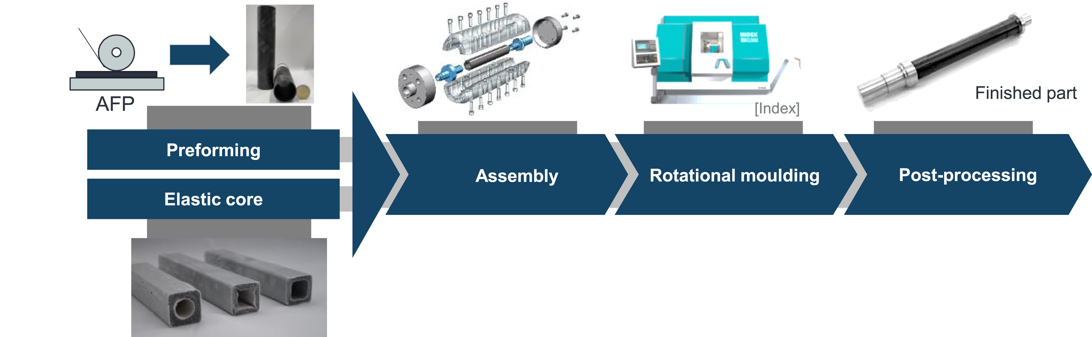
Materials
As preform, a wound and pre-consolidated tube is used. The tubes are manufactured in an automated tape-laying process by Alformet GmbH with an outer diameter of 38 mm and a wall thickness of 1.5 mm, see Figure 3. The preform has a total length of 180 mm and the UD-tapes are wound in an Wound preform of PA6 and carbon fibre.
Results and discussion
In the first step, the rotational moulding process is investigated for smaller diameters using PA6-CF preforms. The preform is inserted into the mould together with a load introduction element (LI) made of metal. The LI is used for the subsequent production of hybrid components but is not the focus of the present work; it will be examined in more detail in further work. The mould has an internal diameter of 40 mm and a length of 200 mm. This results in an annular gap of 1 mm between the preform and the mould, which is to be closed by forming the preform in the rotational moulding process. The first step is the heating phase of the mould. The pre-assembled mould is clamped in the machine and is located inside the heating chamber. For this purpose, 260°C is selected as the setpoint for the heating chamber, which is around 40°C above the melting temperature of 220°C and between the value of Eheleben and the guidelines of the tape manufacturer. The temperature inside the heating chamber is reached within 10°minutes. The mould is then rotated and kept at process temperature for 20°min. The machine itself is limited to
Figure 4 shows the resulting temperature–pressure–time curve of the first tests showing the full cycle for manufacturing. Pressure and temperature profile for the first experiments.
Due to the one-piece design of the mould and the different thermal expansion coefficients of the mould and preform, it is necessary to press out the component. A hand lever press and a specially manufactured punch are used for this purpose. The results of the first tests are shown in Figure 5. In the left part, the outside of the formed part is displayed. Clearly visible are small gaps in between the fibres due to a lack of matrix. The gaps follow the path of winding direction from the preform. A possible explanation is the lack of pressure while forming so matrix cannot migrate into the gaps while the preform is expanding. The lack of pressure theory is supported by looking at the inside of the moulded part (see Figure 5(b)). Clearly visible is the waviness of the inner surface which results from a delamination of the pre-consolidated UD-tapes from one another while the preform is expanding into the final form. Results of first experiments: (a) Surface of formed part with visible gaps between the fibres due to a lack of matrix; (b) View of the inside of the moulded part with visible waviness of tapes.
In the next step, the composite core will be introduced to increase the pressure on the preform during rotational moulding to reduce the waviness on the inside of the part and close the gaps between the fibres due to matrix migration. The Lamé–Navier equation is coupled with the deformation tensor and Hooke’s generalized law.
11
The pressure of the core

with

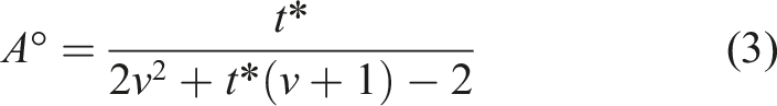
The normalized inner radius of the preform


The outer diameter Different type of pressures occurring in rotational moulding with elastic core.
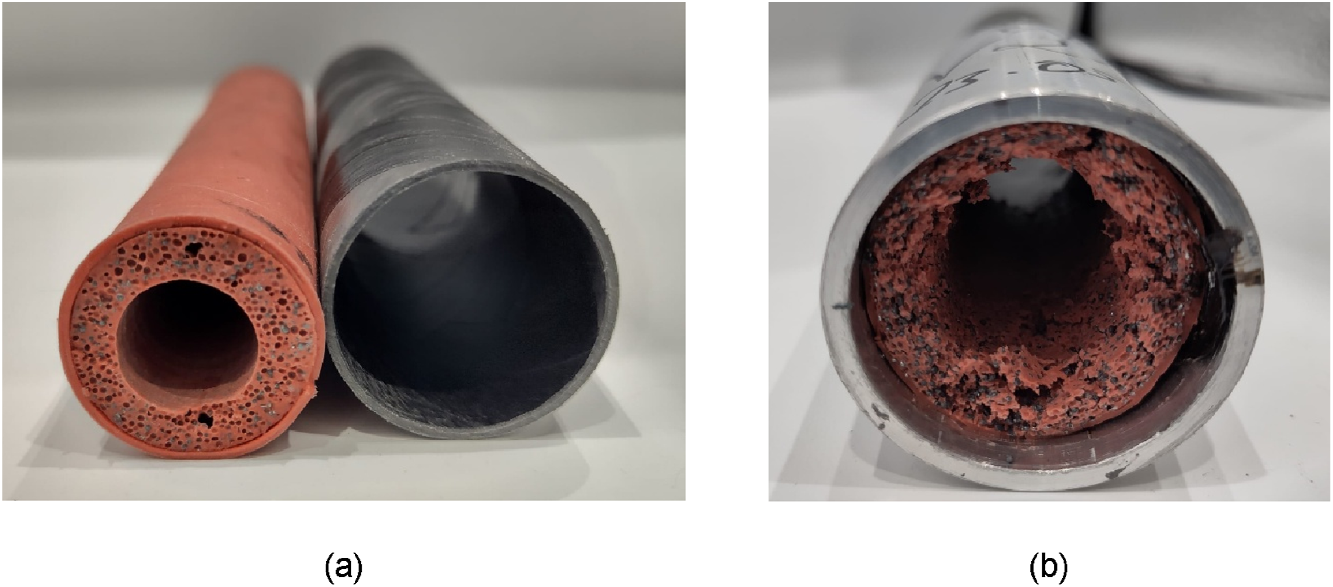
The temperature–time curve was retained for further tests but pressure–time curve changes due to the additional pressure of the core. Another set of experiments were conducted with the new experimental set up. As shown in Figure 7, the further tests show a significantly better forming result on the outside than the previous series of tests. The left side of the figure shows an area where no deformation happened due to uneven temperature distribution. On the right side the completely formed part is displayed. The effect of the core can therefore be assessed as positive. However, there is a lack of deformation of the component on one side. In consequence, the position of the preform inside the mould as well as the position of the mould in the heating chamber was marked. This is to ensure that the exact position of the single components can be tracked and reproduced over a series of experiments. It could be observed that the lack of deformation is always present on the mould side towards the chuck. This is due to the heat conduction between the tool and the chuck. Due to the heat conduction in this direction, the tool part in the spindle direction is below the forming temperature. As a countermeasure, a holding time is introduced between reaching the process temperature and the start of the rotation cycle. Experimental tests have shown that a holding time of 15 min for the utilized geometry is practicable. This results in a new total process time of 65 min for the production of a part. As a result of the first series of tests, it was shown that a rotationally symmetrical part made of PA6-CF can be moulded with the help of an elastic core. But also, the limits of the elastic core could be observed. Several cores were either partially or completely torn due to thermal degradation of the silicone material. Others sticked to the inside of the preform. However, the sticking could be prevented by applying release agent Frekote 770 NC from Henkel GmbH to the outside of the core. However, on average a new core is required every three tests. Figure 8(a) shows a newly caste composite core with wound preform next to it. In Figure 8(b), the part is demonstrated after an experiment with the degraded core on the inside. During the experiments, the heating of the tool was one major issue and led to the uneven results on the outer side of the tubes. To improve the inner surface, the test set up was iteratively modified to assure a defined position of the elastic core before and after the process. Experimental results of forming experiments with elastic core (a) Uneven forming results due to lack of temperature in clamping area of tool (b) completely formed part. Elastic core before and after a set of experiments: (a) Elastic core and wound preform before the experiment; (b) Degraded core sticking to inside of formed part due to degradation.
In order to support the results from visual inspection, micrographs of the cross-section were prepared. The micrographs were taken with a Keyence VHX-7000. Figure 9 shows one of the micrographs with a wall thickness of 1.5 mm, which is in accordance with the specifications from the manufacturer of the semi-finished product. This supports the hypothesis that continuous reinforced thermoplastics can be formed by rotational moulding, but statistical analysis should be conducted to get a better understanding. The results demonstrate the feasibility of rotational moulding also for small diameters. The use of an elastic core and a holding time during heating phase increase the results significant and are therefore recommended. Micrograph of forming result from manufactured specimen.
Conclusion
The aim of this work was to develop the rotational moulding for continuous reinforced thermoplastics with small diameters as a first step of a process chain to manufacture hybrid hollow profiles. The experiments were conducted on a lathe with an integrated heat chamber. The heat chamber consists of multiple layers with insulation and three infrared heaters. A process routine consisting of heating, forming and cooling phase was developed based on existing approaches and recommendation of the semi-finished product manufacturer. During an iterative approach, occurring errors were systematically analysed and the process routine was adapted. In addition, an elastic core was used to increase the pressure during rotational moulding with a significant effect on manufacturing results. The core consists of silicon rubber material in combination with lead balls to maximize the pressure. Furthermore, a holding time in the heating time was introduced to overcome the heat conduction into the lathe. This leads to a total manufacturing time of 65 min per part at a pressure of 0.17 bar. The results demonstrate the feasibility of this approach for forming continuous reinforced thermoplastics with small diameters into a desired shape. Future studies should investigate the manufacturing of hybrid structures, in a combination of fibre reinforced plastics and metallic load introduction elements, will be interesting. The use of elastic cores also allows the production of parts with varying cross-sections and should be investigated in combination with thermoplastic semi-finished products. Furthermore, the mechanical characteristics should be considered for further work. This will provide a base for comparison with other manufacturing technologies. For processing of high-performance thermoplastics such as PEEK-CF, further investigations are necessary, particularly with regard to the core system. This necessity arises from the higher processing temperatures.
Footnotes
Author contributions
Funding
The authors disclosed receipt of the following financial support for the research, authorship, and/or publication of this article: This project was funded by the German Research Foundation (DFG: Deutsche Forschungsgemeinschaft). It is part of the transfer research program ‘Multi-functional high-performance profile systems in intrinsically manufactured fibre composite-metal mixed construction (ProMi)’, FL 197/80-1.
Declaration of conflicting interests
The authors declared no potential conflicts of interest with respect to the research, authorship, and/or publication of this article.
Data Availability Statement
Data will be made available on request.