
Abstract
This paper investigates the adhesive bonding strength of steel-carbon fiber reinforced composites and their simulation analysis method, validating the approach on an automotive hybrid B-pillar to provide a basis for reliable joining of dissimilar materials. By combining adhesive bonding mechanics theory, the material property parameters of DC04 steel and carbon fiber reinforced polymer (CFRP) substrates are determined, offering parameters for finite element modeling of dissimilar material adhesive bonding. Lap shear and butt tensile tests are designed for the adhesive-bonded joints of DC04 steel and CFRP, enabling determination of main mechanical properties of Araldite 2015 structural adhesive and its adhesive performance. A finite element model of the DC04 steel-CFRP adhesive-bonded joint is built to simulate maximum load and failure displacement of the joint, analyze adhesive bonding strength, and compare results with test data. Scanning electron microscopy (SEM) is employed to analyze failure modes of the adhesive joints. A simulation analysis method for adhesive bonding of DC04 steel-CFRP dissimilar materials is established. Adhesive bonding simulations are performed on the automotive steel-CFRP hybrid B-pillar. Based on performance requirements of the B-pillar, simulations are conducted for axial tension, axial compression, lateral bending, and rearward bending, calculating deformation and stress parameters of the adhesive bonding elements under each condition. The carbon fiber composite B-pillar reinforcement plate is manufactured and bonded to the steel outer panel using Araldite 2015 adhesive. A three-point bending test was conducted on the hybrid material B-pillar assembly. Simulation values for displacement and stress are compared with test results, with maximum errors of 2.94% and 3%, respectively. The results validate accuracy and correctness of the adhesive bonding simulation for the dissimilar material B-pillar assembly and demonstrate feasibility and reliability of the proposed adhesive bonding simulation method and strength analysis for the steel and CFRP dissimilar material combination.
Keywords
Introduction
In modern automotive design, lightweighting and safety are key objectives. 1 With the increasing stringency of environmental regulations and the demand for improved fuel efficiency, the combination of steel and composite materials has become an important approach to enhancing automotive structural performance. Carbon fiber composites, known for their excellent strength, stiffness, and corrosion resistance, are widely used in aerospace and automotive industries.2,3 The integration of steel and carbon fiber composites not only reduces weight but also improves overall strength and safety. 4
The traditional mechanical joining methods mainly include bolted joint, riveting, welding, and adhesive bonding. For bolted joint and riveting, Liu et al. investigated the mechanical properties and damage pattern of bolted joints through direct shear tests, considering different bolt numbers, anchorage angles, and arrangements. 5 Chen et al. proposed a method to enhance the strength of long bolted joints (hybrid joints) by using interference body bolt arrangements at both ends of the joint. They conducted finite element (FE) analysis to investigate the load distribution mechanism and slip strength of the hybrid joints. 6 Xie et al. considered the preload and frictional contact between joint components and proposed a method for generating block-mapped hexahedral meshes and finite element modeling (FEM) of bolted joint. They constructed FEM for single-bolt and double-bolt structures. 7 Seok et al. proposed a novel FE-based modeling method for cold-formed steel (CFS) bolted joint. This method is capable of simulating the nonlinear behavior of bolted joint, characterized by bolt slip and progressive bearing, and uses a series of connector elements (defined with friction and plasticity models) to simulate the bolt slip bearing behavior. 8 For riveting, Yan et al. conducted a comprehensive evaluation of four riveting methods: net riveting, gasket riveting, bushing riveting, and gasket-bushing riveting. They investigated the effects of interference levels, rivet damage, and joint strength under quasi-static tensile loading on CFRP riveted joints. The results indicated that gasket riveting performed better than bushing riveting and the gasket-bushing riveting. 9 Zhang et al. investigated the forming mechanism and quasi-static tensile failure of single-lap electromagnetic riveted joints with different rivet hole clearances. They quantitatively evaluated the deformation characteristics and mechanical properties of these joints. 10 Although bolted joints and riveting can provide high initial strength, they tend to induce stress concentrations in the material, leading to cracks or damage. Additionally, they often increase weight and complexity, limiting their application in steel-CFRP bonding.
For welding technology, Gao et al. used Sn-Bi low-temperature solder to perform ultrasonic-assisted soldering of silica glass and 2024Al in order to alleviate the residual stress issues in the silica glass/2024Al joints. They investigated the effects of welding temperature and the Bi content in the solder on the properties of the welds. 11 Ouyang et al. studied the microstructural evolution, interfacial reactions, shear properties, and fracture behavior of Sn-Bi Cu core solder joints during reflow and thermal aging processes. The results showed that the solder joints exhibited the highest shear strength after reflow soldering, and the shear strength decreased with thermal aging. The fracture behavior of the joints primarily occurred within the solder and at the upper interface layer. 12
Kormoczi et al. evaluated the electrical and mechanical properties of laser-welded nickel-plated steel sheets, revealing the effects of surface pretreatment conditions, filler material quantity, laser power, and exposure time on the characteristics of laser welds. They concluded that when surface pretreatment conditions and processing parameters are properly optimized, laser welding can produce joints with excellent electrical conductivity and sufficient mechanical stability, meeting the critical specifications for battery joining technology. 13 Zhang et al. enhanced the bonding strength of laser-welded 304 stainless steel/carbon fiber reinforced thermoplastic (CFRTP) joints through laser texturing. They systematically studied the close relationship between surface texture spacing, porosity characteristics, and the tensile properties of the joints. 14 Although welding technology can provide strong joints, the thermal sensitivity of carbon fiber composites and the mismatch in the coefficient of thermal expansion between the composite and steel make welding operations challenging and may affect the material properties.
In contrast, adhesive bonding has become the ideal choice for steel-carbon fiber composite bonding due to its ability to avoid local damage, evenly distribute stress, and simplify assembly. Structural adhesives, in particular, are widely used in various structures due to their excellent corrosion resistance, ability to adapt to complex shapes, and strong load-bearing capacity. 15 Wang et al. proposed a method for ultrasound-assisted reinforcement of adhesive bonding in aluminum/CFRP joints. Under ultrasonic vibration, the probability of reaction between the cyano groups in the adhesive film and the hydroxyl groups on the aluminum surface increases, leading to the formation of more carbonyl and Al-N chemical bonds between the adhesive film and the aluminum, thereby enhancing the bonding performance of aluminum/CFRP. 16 Qiao et al. conducted comprehensive characterization of the failure behavior of adhesive bonding in metal-metal, metal-CFRP, and CFRP-CFRP material combinations under shear deformation using single-lap shear testing. The characterization in this work provides quantitative data that aids in a better understanding of shear failure in adhesive bonding across different bi-material combinations. 17 Zhang et al. presented the research findings on the bonding behavior between wet-layup CFRP and corroded Q355 B steel plates. The results show that the impact of corrosion on the bonding performance of CFRP and steel depends on the failure modes induced by the properties of the adhesive material. 18 Ke et al. investigated the performance evolution of epoxy adhesive and CFRP-steel epoxy adhesive joints after exposure to hot and humid conditions. Three exposure temperatures (25°C, 50°C, and 75°C) and three exposure durations (24 h, 120 h, and 360 h) were considered. The dynamic mechanical behavior and tensile properties of the bulk adhesive were studied using dynamic mechanical analysis (DMA) and tensile testing, respectively. 19 Liu et al. proposed an accurate evaluation approach for the structural adhesive bonding between aluminum and CFRP. This method reliably and precisely predicts the performance of adhesive joints through a short-term experimental testing procedure, focusing on both intrinsic and extrinsic factors that influence adhesive strength. 20 Riccio A et al. combined different types of joints and couplings to develop accurate numerical models for predicting the tensile mechanical behavior of composite joints, which were employed in numerical simulations of bonded and hybrid joints. 21 Acanfora V et al. analyzed the feasibility of weight reduction for sandwich panels with DfAM-designed cores by adjusting additive manufacturing infill parameters. The results showed that using PP cores and CFRP face sheets, this method can reduce structural weight by 28% while improving energy absorption characteristics. 22
The B-pillar of a vehicle, as a crucial load-bearing component of the body, plays a direct role in the vehicle safety, rigidity, and crash energy absorption performance. Its design for bonding the inner and outer panels significantly impacts these characteristics. Ozturk compared the energy absorption performance under crushing load of homogeneous B-pillars designed with B1500HS-T25, AA2024-T351, and AA6061-T6 materials, as well as hybrid B-pillars designed with combinations of these materials. The optimization study focused on a hybrid B-pillar with B1500HS-T25 in the upper section and AA6061-T6 in the lower section. 23 Zhang et al. proposed an optimization method for hybrid material B-pillar design. After optimization, the weight of the hybrid material B-pillar was reduced by 26.44%. The increases in intrusion at P2 and intrusion speed at P1 were 23.99% and 0.63%, respectively. The results significantly improved both lightweight performance and side-impact safety. 24 Zhang et al. focused their research on layer optimization and structural refinement of carbon fiber composite B-pillars, deriving a layer-down stacking scheme that significantly reduced weight by 57.5%. A comprehensive evaluation was conducted using various indicators, including deformation mode, intrusion depth, and intrusion speed. The results confirmed that the composite B-pillar demonstrated side-impact resistance comparable to that of the original metal B-pillar, ensuring strong passenger protection. 25 Wang et al. proposed a hybrid method combining an improved particle swarm optimization algorithm (MPSO), the Technique for Order Preference by Similarity to Ideal Solution (TOPSIS), and principal component analysis (PCA) to better enhance the lightweight and crashworthiness performance of the B-pillar. The results showed that, under the condition of reaching the peak impact velocity, the B-pillar weight was reduced by 20.7%, while the peak intrusion deformation increased by 23.5% and 41.7%, respectively. 26 Du et al. used the material and thickness of the lower joint of the B-pillar as design variables and generated experimental samples through design of experiments (DOE). A multi-objective optimization of the lower section model of the B-pillar was performed using response surface methodology and simulated annealing algorithm to determine the final optimized solution. This approach effectively enhanced the stiffness and crashworthiness of the vehicle body. 26
Due to the significant differences in physical and chemical properties between steel and CFRP, traditional adhesive bonding methods often face challenges in interface strength and bonding stability, leading to joint failure. Additionally, as a critical load-bearing component in the vehicle body, the B-pillar plays a vital role between the door and roof, providing vertical rigidity and safety protection. In side-impact and rollover accidents, the bonding strength of the B-pillar directly affects the vehicle crash resistance. Effective B-pillar bonding not only enhances collision safety but also significantly reduce injury to occupants, protecting their survival space. Therefore, this study explores the adhesive bonding strength and simulation analysis methods for steel and CFRP dissimilar material joints. A finite element modeling approach based on adhesive mechanics theory is proposed, providing theoretical support and technical assurance for the reliability of dissimilar material bonding. This study designs and conducts shear and tensile tests on adhesive joints between DC04 steel and CFRP substrates to obtain key mechanical performance parameters, further refining the simulation model for adhesive bonding. Combining electron microscopy analysis, the failure modes of the joints are investigated, and the application of this method in automotive hybrid material B-pillars is validated. The results show that the proposed steel-CFRP adhesive bonding simulation method is in excellent agreement with experimental data, with the maximum error being only 2.94% and 3%, fully demonstrating the accuracy and feasibility of the method. This research not only provides an innovative solution for automotive lightweight design but also lays a solid foundation for the application of multi-material dissimilar material bonding technologies, holding significant academic value and practical engineering implications. The findings offer new insights and technical support for the optimization and development of high-performance multi-material bonding technologies in the future automotive industry. 27
Mechanical performance parameters of adhesive-bonded joints between dissimilar materials
When the vehicle body is subjected to various working conditions, adhesive structures may experience diverse loading effects. The combined influence of load types and joint design significantly impacts the overall performance of adhesive-bonded joints. During this process, possible failure modes of the adhesive-bonded joints include internal separation, adhesive interface failure, substrate fracture, or even a combination of these failure modes. To ensure the stability and safety of the adhesive bonding structure, it is crucial to conduct in-depth research on the different working conditions it may encounter and the interaction between these conditions and the joint design.
Test materials and their mechanical properties
Metal substrate
The DC04 steel used in this test is classified as a deep-drawing steel. It is characterized by relatively low yield strength and tensile strength, but excellent ductility. Due to these properties, DC04 steel has been widely adopted in the automotive industry and is suitable for manufacturing parts with complex structures that require high plastic deformation. In order to accurately obtain the basic mechanical property data of DC04 steel, we follow the GB 2975-82 standard, select a steel plate with a thickness of 2 mm and a parallel width of 20 mm. Tensile test is carried out according to the standard procedure of GB/T228-2002, and the loading speed is maintained at 2 mm/min during the experiment. The experiment is shown in Figure 1. Its specific mechanical properties are shown in Table 1. Tensile test of DC04 steel: (a) experimental sample; (b) experimental equipment. Mechanical properties of DC04.

Carbon fiber composite substrate
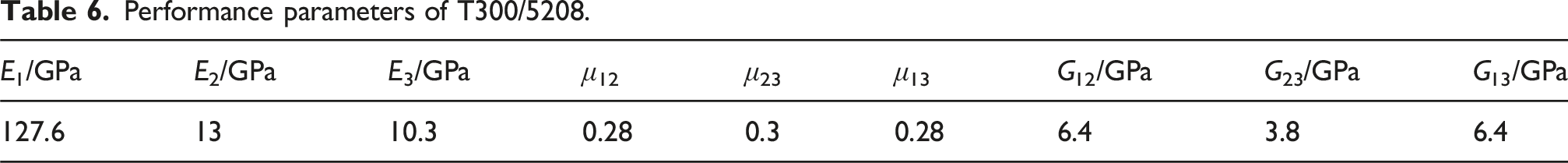
Performance parameters of T300/5208.

Mechanical performance testing of dissimilar material adhesive bonding
Test plan
The carbon fiber reinforced resin-based composite material used in this study employs a prepreg cutting and stacking process. The fiber fabric type is T300, and the layup sequence is [0/90]7. Carbon fiber reinforced composites have a very high carbon content, which results in excellent and stable mechanical performance characteristics. The main performance parameters of the CFRP laminate are shown in Table 2. The selected DC04 steel is a low-carbon cold-rolled sheet, widely used in automotive manufacturing, especially suitable for the production of outer panels and internal structural parts. The adhesive used in this study is Araldite 2015 epoxy resin structural adhesive. Manufactured by Vantico, Araldite 2015 is a two-component, paste-like adhesive that cures at room temperature. Known for its excellent strength and toughness, this adhesive features unique thixotropic properties, allowing it to effectively fill larger gaps and remain non-dripping on vertical surfaces. The maximum allowed sag thickness is up to 10 mm. It is especially suited for bonding composite materials such as SMC (Sheet Molding Compound) and GRP (Glass Reinforced Plastic).
Preparation of adhesive-bonded joints
In this study, in order to achieve a strong and stable bond between carbon fiber composites and metal materials, Araldite 2015 structural adhesive is selected as the bonding medium. To address the challenges of durability and stability in this dissimilar material bonding, the research focuses on the performance of the adhesive under two typical loading conditions: butt joint tensile testing and single-lap shear testing. To obtain reliable test data and ensure comparability between different batches of tests, strict standardized procedures are implemented for both key mechanical performance tests. Each test type is carefully designed and executed with five parallel groups to ensure that the results accurately reflect the butt joint tensile strength and shear load-bearing capacity of Araldite 2015 adhesive in practical engineering applications.
In the lap test, the selected metal bonding components are made of DC04 steel plates, with specific dimensions of 100 mm × 25 mm × 2.0 mm. According to the ATSM D1002 standard, the lap length is 37.5 mm to ensure that the adhesive layer is in a pure shear state. On the other hand, the carbon fiber reinforced part is made from T300/5208 prepreg material, with dimensions of 100 mm × 25 mm × 1.8 mm. Additionally, to ensure uniformity of the adhesive layer, its thickness is precisely controlled at 0.5 mm. Figure 2 shows the detailed construction of the shear test specimen, including the bonding area between the metal and carbon fiber composite, as well as the actual distribution of the adhesive layer. Dimensions of the single-lap shear test specimen.
In the butt joint test design, a cubic-featured butt joint specimen is fabricated, consisting of three parts tightly integrated through the adhesive bonding process: two steel base layers at the top and bottom, and a composite material core layer in the middle. The top and bottom steel components are made of DC04-grade steel, with dimensions of 100 mm × 25 mm × 25 mm. The core layer between them is made of the high-performance epoxy resin carbon fiber composite T300/5208, with dimensions of 25 mm × 25 mm × 1.8 mm. Throughout the entire joint structure, the adhesive layer thickness is consistently maintained at 0.5 mm. Figure 3 visually presents the detailed structural layout of the various layers and their joints within the butt tensile specimen. Dimensions of the butt tensile test specimen.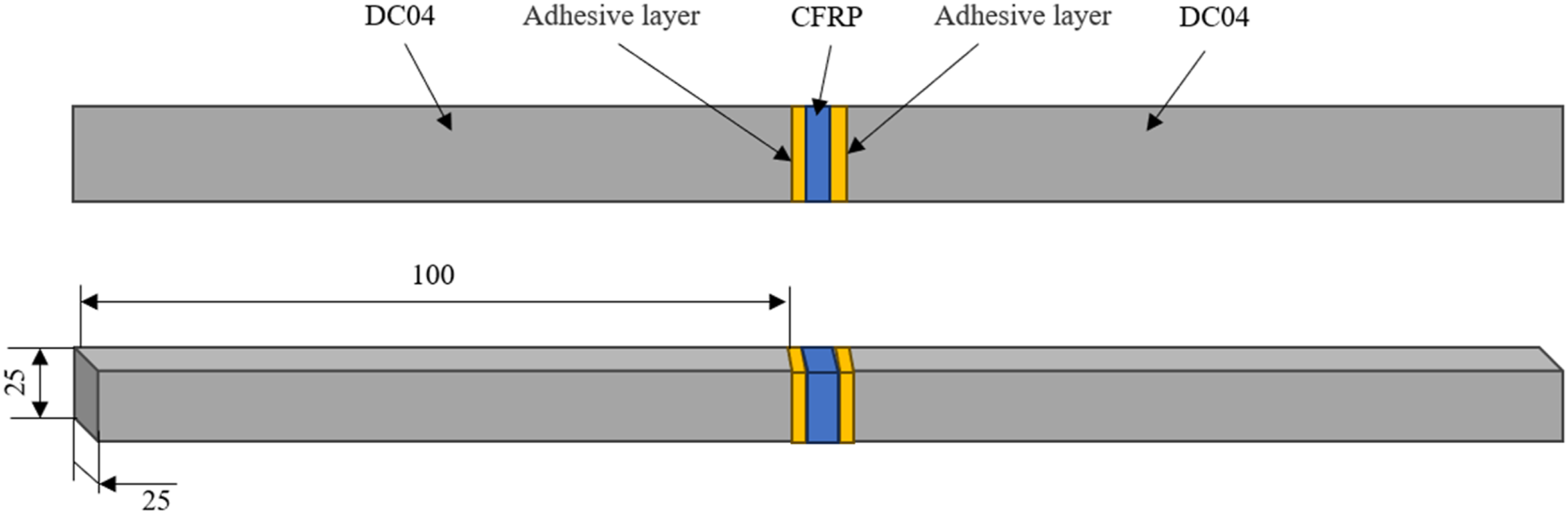
The adhesive-bonded joint fabrication process is shown in Figure 4. In order to adjust the surface properties, the steel plate and carbon fiber plate were cut to 100 mm × 25 mm size, treated according to ISO 4587:2003 standard, and the surface was sanded with 180 mesh sandpaper to remove impurities and improve the wetting performance of the adhesive. Then, deep cleaning and degreasing with acetone, drying for 24h and then gluing treatment. In the final stage, the two plates are carefully aligned and clamped under pressure to ensure uniform adhesive layer thickness and to prevent any displacement of the plates during the curing process. After thoroughly removing any excess adhesive, Based on resin curing kinetics, 150°C/180 min curing standard was selected (GB/T 2567-2008), the assembled joint is placed into an RHP-FB-8000BT intelligent temperature and humidity control chamber. The specific operating parameters of the chamber are detailed in Table 3. After a curing cycle of 180 min at the set temperature of 150°C, the joint is fully hardened, as shown in Figure 5.
28
Preparation process of the adhesive-bonded joint. RHP-FB-8000BT programmable constant temperature and humidity chamber parameters. Test specimens: (a) Lap shear specimen; (b) Butt tensile specimen.


Performance testing methods
Tests were conducted on both lap shear and butt tensile performance to thoroughly analyze the intrinsic properties of the structural adhesive and its bonding effectiveness under various loading conditions. This is done to obtain shear and tensile performance parameters of the adhesive. The quasi-static tensile shear tests were carried out using a universal testing machine, as shown in Figure 6.
28
During the butt tensile and lap shear tests, an electronic universal testing machine with a rated load of 100 KN is used. Additionally, the test is conducted with a specimen width limit of 570 mm and an effective beam distance of 1200 mm, which is sufficient to meet various testing requirements. Performance testing equipment: (a) Lap shear performance test; (b) Butt tensile performance test.
In the lap shear test, balance gaskets are added to the fixture joints to prevent skewing forces. In the butt tensile test, the fixtures are precisely connected to the tensile machine using a cross-pin shaft to eliminate non-axial forces. Figure 6 visually illustrates the actual testing setup. The loading speed is set to 2 mm/min according to the GB/T7124-2008 standard. For each combination of adhesive joint parameters, five sets of repeated tests are performed. The data acquisition module is capable of instantly capturing the peak load during the transient failure process and dynamically generating load-displacement curves for both lap and butt joints in the shear and tensile tests. This enables intuitive analysis and quantitative evaluation of the material performance.
Adhesive material parameter acquisition
The fractured specimens and fracture morphology are shown in Figure 7.
28
The relationship between load and relative displacement for the butt tensile and lap shear specimens during the testing process is presented in Figure 8.
28
As shown in Table 4,
28
by strictly following the testing procedures and carefully processing the obtained data, the tensile strength of Araldite 2015 structural adhesive is measured to be 20.5 MPa, with a corresponding tensile modulus of 1850 MPa. In terms of shear performance, the adhesive exhibited a shear strength of 17.8 MPa and a shear modulus of 502 MPa. The key parameters applied to the cohesion model are shown in Table 5.
29
Failure modes of the specimens: (a) Failure mode of the lap shear specimen; (b) Failure mode of the butt tensile specimen. Load-displacement curve of the specimens: (a) Lap shear specimen; (b) Butt tensile specimen. Mechanical properties of Araldite 2015 structural adhesives. Key parameters of cohesion model.


SEM fracture morphology analysis of the adhesive-bonded joints
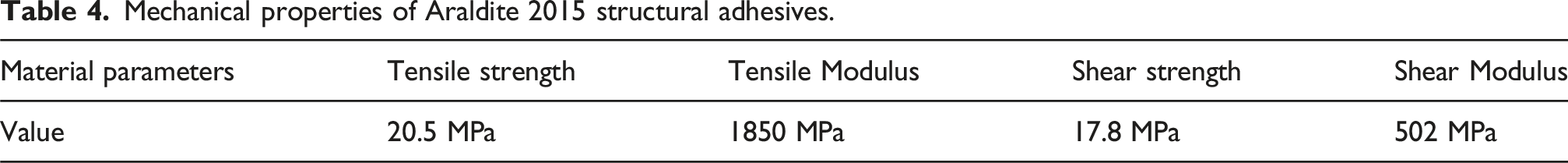
In this test, the SEM is used to observe and analyze the failure of dissimilar material adhesive-bonded joints, as shown in Figure 9. Test specimens are collected from the joint failure region, and materials that meet the testing requirements are selected for observation. Test equipment: (a) SEM; (b) Sputter coater.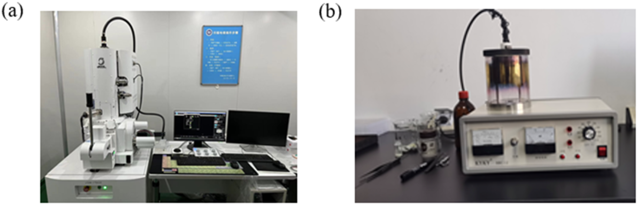
The fracture surface of the CFRP/DC04 bonded lap joint is shown in Figure 10. The adhesive layer fracture surface in region “1” is smooth with no significant characteristic marks, indicating that this region primarily exhibits interface failure under tensile loading, meaning the bonding strength between the substrate and the adhesive is relatively weak. The adhesive around region “1” shows obvious plastic deformation, revealing that the adhesive exhibits some toughness characteristics during fracture. Since Araldite 2015 adhesive is an epoxy resin polymer, under quasi-static tensile conditions, its molecular chains have enough time to rearrange their structure to accommodate the tensile direction. This allows for plastic deformation under tensile load and ultimately results in a ductile fracture mode at the end of its service life. The tough fracture characteristics observed in region “2” confirm that, under quasi-static tensile testing conditions, the dominant failure mode of the fracture surface is cohesive failure. Therefore, under quasi-static tensile loading, the primary damage mechanism of the CFRP/DC04 bonded lap joint fracture surface is cohesive failure, accompanied by a small amount of failure due to issues at the adhesive interface. Microstructure of the shear fracture surface of the quasi-static bonded lap joint.
CZM theory
Cohesive zone model (CZM)
The CZM does not require pre-crack in structures, and it is outstanding with relatively simple calculation and high simulation accuracy. Thus, CZM has been widely used to simulate the mechanical behaviors of adhesive layers under various working conditions. The constitutive law assumes that the traction stress of material under external load is intensified linearly with the increase in displacement during the initial stage. Degradation begins when the stress and/or strain can satisfy damage initiation criteria. Material stiffness is degraded and the degradation rate is described by the damage evolution law. Finally, the traction stress decreases to zero and the material fails completely. The mechanical response provided in ABAQUS comprises three stages: initial elasticity, damage initiation and damage evolution. The relationship between nominal traction stress and nominal strain was established using an elastic constitutive matrix. The quadratic stress criterion is widely used in failure prediction of structural adhesives, and it can be expressed as
When the damage initiation criterion is satisfied, the material stiffness degrades and enters the damage evolution stage. The damage evolution is decided by the law based on fracture energy or effective displacement. The first power law based on energy is used in this work, which is expressed as
For linear softening, a scalar damage variable D reduces as equation (5) is used to govern the material damage process. The value of D increases monotonously from 0 to 1 from initial damage to complete damage, indicating the degradation of material stiffness. D is expressed as follows: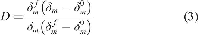

Establishment of damage initiation criterion
The q-stress criterion (as shown in equation (5)) was used to fit all the test data.
The damage initiation displacement of CZM was determined by the damage initiation criterion. For the established q-stress criterion, the damage initiation displacement under the mixed mode can be described as

Embedded the cohesive constitutive response involving stress damage criterion into ABAQUS by a user-defined material subroutine (VUMAT). On the basis of the modified CZM, numerical simulation was carried out and then verified using the experiment results.
Finite element modeling and validation of adhesive bonding with dissimilar materials
When simulating adhesive-bonded joints using shell elements, although the composite adhesive structure is simplified and the modeling and convergence are relatively straightforward, the accuracy is not as high as that of solid elements, especially when dealing with normal and shear stresses in all three directions. The shell element model is not capable of handling this effectively. Therefore, while three-dimensional solid models require higher computational performance and convergence, they can provide a comprehensive stress analysis of adhesive structures and accurately capture out-of-plane responses and stress concentration phenomena. For this reason, this section uses a three-dimensional solid element model to perform finite element modeling of lap adhesive joints.
CFRP substrate model
Performance parameters of T300/5208.
The single-layer thickness, stacking angle, and stacking sequence of the CFRP substrate are set as follows. The axial direction of the substrate is taken as the reference direction for stacking, while the direction perpendicular to the laminate plane is considered the normal direction for fiber stacking, as shown in Figure 11. When performing finite element meshing of the CFRP substrate, an 8-node three-dimensional solid element (C3D20) is used. This type of element includes three Gaussian integration points in each of the three spatial directions. During numerical integration, such an element design allows for precise integration of the interpolation functions in the element stiffness matrix, thereby significantly improving the accuracy and reliability of the stress analysis results. CFRP substrate stacking information.
DC04 substrate model
Taking the lap joint as an example, the balance spacer and the DC04 steel substrate are treated as a single unit for the simulation design. The material properties of the DC04 steel are set according to the parameters in Section 2.1.1. Since the DC04 substrate may undergo plastic deformation under loading, which directly affects the stress distribution and load-bearing performance in the joint area, it is necessary to incorporate elastic-plastic material properties when constructing the finite element model. Additionally, a suitable quasi-static nonlinear analysis algorithm is applied.
Considering the impact of mesh size on simulation accuracy and the computational time cost, it is decided to use mesh elements with edge lengths ranging from 0.4 to 0.5 mm and to generate a regular hexahedral (Hex) mesh structure using automatic meshing techniques. For the DC04 substrate model, four levels of mesh refinement are applied, particularly in key areas where high stress concentration effects are expected. These areas are further refined to enhance the accuracy of the simulation results.
Adhesive layer model
For cohesive layers, a single element through the thickness is sufficient and recommended to avoid artificial compliance.
30
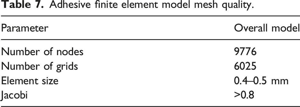
If the adhesive layer thickness is subdivided into two or more layers of Cohesive elements, it can lead to highly unreliable results, potentially causing erroneous analysis conclusions. Therefore, adhering to best practices, the meshing of the adhesive layer in the thickness direction must be strictly limited to a single Cohesive element. A fixed boundary condition is applied to the one side of the substrate to restrict all translational and rotational degrees of freedom, whereas the other end was applied with translational displacement along the x direction to restrict the remaining degrees of freedom. The ABAQUS/Explicit module was used for analysis, and geometric nonlinearity of materials was considered. To simulate the quasi-static experiment, the loading speed was set as 2 mm/min. A small viscous damping coefficient (10 −5) was introduced into the model to avoid numerical calculation instability that may occur when the model approached catastrophic failure in the simulation. Based on this, two typical bonding models are successfully established. Then, according to the actual material properties, the appropriate attributes were assigned to each part, with the adhesive layer settings based on the performance parameters measured in Section 2.2.4. Figure 12(a) and 12(b) show the lap and butt joint finite element models, respectively And the parameters of the CZM for adhesive are presented in Tables 5. In summary, the mesh quality data of the adhesive finite element model are shown in Table 7. Adhesive bonding finite element models: (a) Lap; (b) Butt. Adhesive finite element model mesh quality.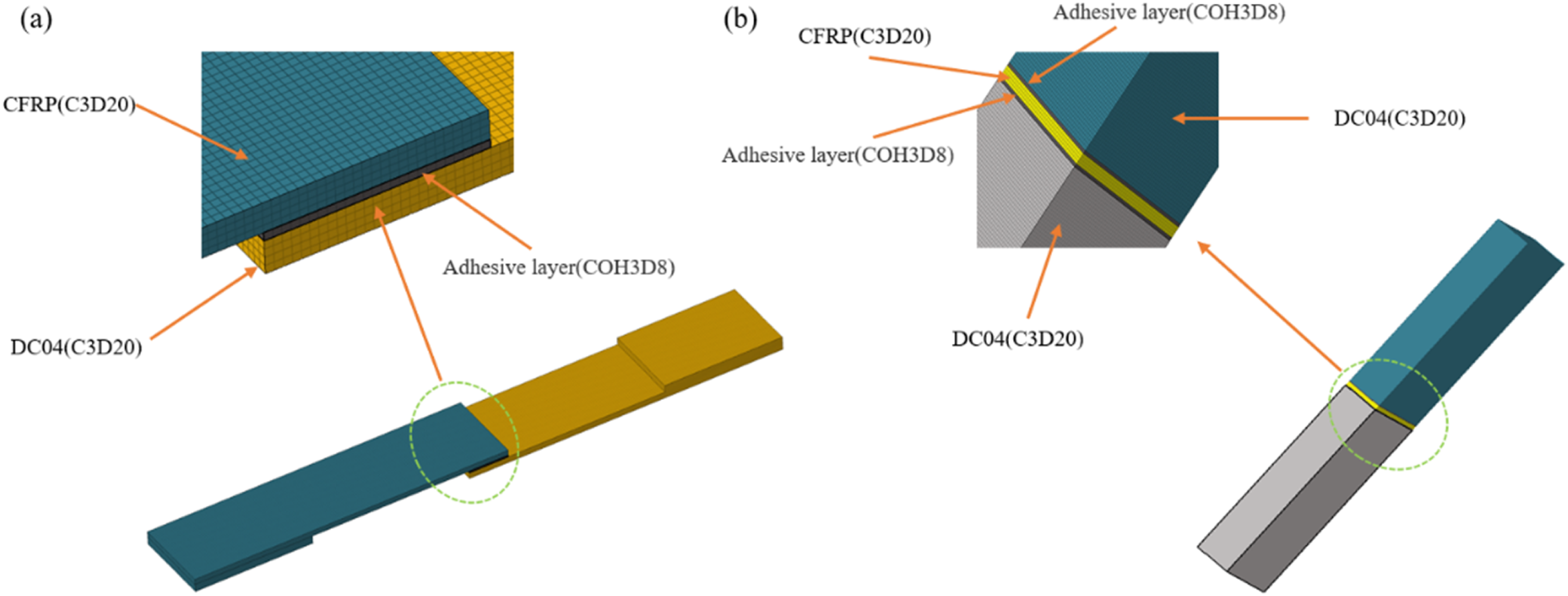
Damage parameter analysis
To verify the effectiveness of the simulation analysis, the failure load of unaged joints and the x/y displacement at the end of the steel plate after complete failure were extracted from the output results of field variables in the software. The failure load was obtained by calculating the reaction forces of all nodes at the fixed constraint end, and the displacement was acquired by averaging the displacement of all nodes at the plastic deformation end of the steel plate.
Taking the single-lap adhesive-bonded joint as an example, its stiffness asymmetry can be categorized into three types: first, asymmetry caused by geometric parameter differences while the material is homogeneous; second, asymmetry caused by differences in material properties while the geometric parameters are the same; and third, asymmetry caused by differences in both geometric parameters and material properties. The single-lap adhesive-bonded joint studied in this research belongs to the third type. Compared to a stiffness-symmetric joint, the maximum stress and the initiation point of failure within the adhesive layer of a stiffness-asymmetric joint will change, significantly affecting the overall mechanical performance of the joint. When constructing an analytical model to solve the stiffness-asymmetric joint problem, simplifications often have limitations, and the computational process tends to be more complex. However, using the FEM to solve for the stiffness-asymmetric adhesive joint can effectively improve the accuracy of the calculation results.
Figure 15 illustrates the full process curve of a single-lap adhesive-bonded joint, from the initial stiffness degradation to final failure. This curve vividly depicts the progressive loss of load-bearing capacity of the joint. During this process, the key damage parameter “Scalar Stiffness Degradation” (SDEG) is used as a metric, providing a quantitative analysis of the damage evolution within the cohesive contact elements. This scalar index effectively tracks the gradual weakening of bonding performance as the load increases, offering a comprehensive reflection of the overall health and failure progression of the joint structure.
In the actual fracture process, while the adhesive layer remains intact, SDEG = 0; when the adhesive bonding is completely lost, SDEG = 1. As shown in Figure 13(a), the stiffness degradation process initially occurs in the adhesive region adjacent to the left CFRP panel. As the load intensity increases, the process transitions to the stage shown in Figure 13(b), where the adhesive layer near the right end of the joint, close to the DC04 panel, also starts to experience significant stiffness degradation, rapidly approaching or even reaching the critical state of SDEG = 1. At this point, in the COH3D8 simulation element at the right edge of the adhesive layer, close to the DC04 substrate, once the accumulated energy loss matches the fracture threshold in the model, the element is marked as failed and removed from the calculation. This simulates the potential crack formation at this location in a real single-lap adhesive-bonded joint, as shown in Figure 13(c). In the CFRP/DC04 single-lap adhesive-bonded joint, cracks typically initiate from the side of the DC04 substrate, where the stiffness is lower. As the load increases, the crack gradually extends inward from this initial location until the entire adhesive layer loses its bonding capacity, ultimately leading to joint failure. After joint failure, irreversible plastic deformation is observed in the DC04 substrate region, as shown in Figure 13(d). Failure process of the single-lap adhesive-bonded joint: (a) Stiffness degradation occurs; (b) Degradation reaches SDEG = 1; (c) Crack formation; (d) Complete adhesive layer failure.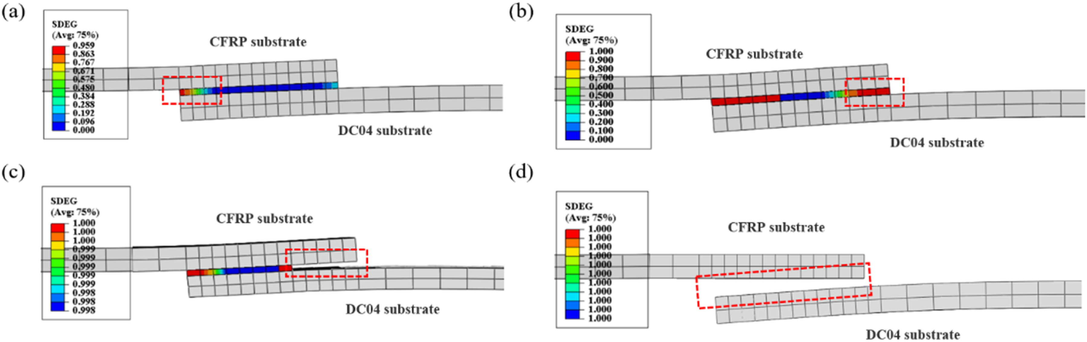
Load-displacement validation
To validate the model prediction of the adhesive structure load-bearing capacity, the load-displacement curves obtained from simulations and tests are compared, as shown in Figure 14(a) and (b). The simulation curve closely matches the trends and magnitudes of the five test curves, demonstrating that the finite element model can accurately simulate the adhesive-bonded joint behavior. Furthermore, Tables 8 and 9 provide detailed listings of the maximum loads endured by various adhesive joints before failure, the corresponding failure displacements, and the ratios between the finite element simulation results and actual test measurements, offering strong data support to assess the validity and accuracy of the model predictions. Comparison of simulation and test load-displacement curves: (a) Lap joint; (b) Butt joint. Comparison of lap joint finite element analysis results and test values. Comparison of butt joint finite element analysis results and test values.


For the load portion of the Araldite 2015 structural adhesive lap joint test: The maximum load obtained from the finite element simulation for Specimen 1 is 12.96 KN, compared to the test value of 12.67 KN. The ratio of the simulation value to the test value is 1.02, indicating that the simulated load is slightly higher than the actual load, but the difference is small. For the other specimens (Specimens 2 to 5), the ratio of simulated load to test load ranges from 0.96 to 1.06, with the simulation values closely matching the test values, demonstrating that the finite element model shows good consistency in predicting the maximum load.
For the failure displacement portion: The failure displacement obtained from the finite element simulation for Specimen 1 is 1.61 mm, compared to the test value of 1.59 mm, with a ratio of 1.01, indicating good consistency. For the other specimens (Specimens 2 to 5), the ratio of simulated to test failure displacement ranges from 0.93 to 1.06, also demonstrating that the finite element simulation has a certain level of accuracy in predicting the failure displacement. Although there are slight differences between the simulation and test values for individual specimens, the results still meet the required standards.
For the load portion of the Araldite 2015 structural adhesive butt joint test: The finite element simulation value for the maximum load of Specimen 1 is 10.98 KN, compared to the test value of 10.91 KN. The ratio of the simulation value to the test value is 1.01, indicating that the simulation results are very close to the test results, with a small error. Other specimens (Specimens 2 to 5) show a similar trend, with the ratio of simulated load to test load ranging from 0.94 to 1.22, demonstrating that the finite element simulation has high accuracy in predicting the maximum load, although some slight fluctuations exist.
For the failure displacement portion: For Specimen 1, the finite element simulation value for the failure displacement is 2.39 mm, compared to the test value of 2.63 mm. The ratio of the simulation value to the test value is 0.91. Although there is some underestimation, the error still falls within the acceptable range. The ratios of simulated failure displacement to test displacement for other specimens (Specimens 2 to 5) fluctuate between 0.91 and 1.19. While there is some deviation in the finite element simulation when predicting failure displacement, the overall trend still reflects the true physical behavior.
In summary, the finite element model simulates the load and failure displacement of lap and butt joints, and in most cases, the simulation results align well with the test values. The ratio of simulation values to test values ranges from approximately 0.91 to 1.06, indicating that the finite element model has a high level of reliability and practicality when predicting the performance of such joints. However, in some individual cases, there are slight deviations between the simulation and test values, as the properties of CFRP materials, the critical fracture energy release rate of the adhesive layer, and adhesive strength are influenced by various factors such as adhesive layer thickness, environment, processing conditions, and curing defects. Although there are discrepancies between the simulation and test results, they fall within a reasonable range. Using cohesive elements to model and predict joint adhesive strength is both feasible and effective.
Analysis of adhesive bonding performance of inner and outer panels of the B-Pillar
Global B-pillar model grid quality data.


Hybrid material adhesive bonding B-pillar assembly before inner panel layup.
Axial tension
To evaluate the ability of the adhesive bonding in the hybrid material B-pillar to withstand longitudinal tensile forces during automotive collisions, and to ensure that the adhesive bonding in the B-pillar can provide adequate occupant protection under extreme conditions, a finite element simulation model for axial tension of the B-pillar assembly is established. The material parameters for the steel outer panel are set according to the performance parameters in Section 2.1.1, while the material parameters for the carbon fiber composite inner panel are set according to the T300/5208 performance parameters in Table 2 of Section 2.1.2. The material parameters for the adhesive element are set according to the measured performance parameters in Section 2.2.4. The boundary conditions and loading setup for the hybrid material B-pillar assembly are shown in Figure 16(a). (1) Constraints: The translational freedom along the Y-axis and rotational freedoms along the XYZ-axes of the top of the hybrid material B-pillar assembly are constrained. The translational and rotational freedoms along the XYZ-axes of the bottom of the hybrid material B-pillar assembly are also constrained. (2) Loading: At the upper part of the hybrid material B-pillar assembly, RBE2 elements are used to connect all upper nodes at a single point, where a force of 10,000 N in the positive Z-direction is applied. Axial tension working condition: (a) Constraints and load; (b) Displacement contour plot; (c) Stress contour plot.

As shown in Figure 16(b) and 16(c), the displacement and stress contour plots for the adhesive bonding element in the hybrid material B-pillar assembly are presented. The maximum displacement in the Z-direction for the adhesive-bonded joint in the hybrid material B-pillar assembly is 0.401 mm, and the maximum stress is 5.332 MPa.
Axial compression
To evaluate the ability of the adhesive bonding in the hybrid material B-pillar to withstand longitudinal compressive forces during a collision, and to ensure that the adhesive bonding in the B-pillar effectively maintain the structural integrity of the vehicle body during the collision, thereby providing occupant protection, a finite element simulation model for axial compression of the B-pillar assembly is established. The boundary conditions and loading setup for the hybrid material B-pillar assembly are shown in Figure 17(a). (1) Constraints: Constrain the translational degree of freedom along the Y-axis and the rotational degrees of freedom along the XYZ-axes at the top of the hybrid material B-pillar assembly; constrain the translational and rotational degrees of freedom along the XYZ-axes at the bottom of the hybrid material B-pillar assembly. (2) Loading: At the upper part of the hybrid material B-pillar assembly, connect all the upper nodes to a single point using RBE2 elements, and apply a force of 10,000 N in the negative Z-direction at this point. Axial compression working condition: (a) Constraints and load; (b) Displacement contour plot; (c) Stress contour plot.

As shown in Figure 17(b) and 17(c), the displacement and stress contour plots for the adhesive bonding element in the hybrid material B-pillar assembly are presented. The maximum displacement in the Z-direction for the adhesive-bonded joint in the hybrid material B-pillar assembly is −0.401 mm, and the maximum stress is 5.332 MPa.
Lateral bending
To evaluate the ability of the adhesive bonding in the hybrid material B-pillar to withstand lateral bending forces during a side-impact collision, and to ensure that the adhesive bonding in the B-pillar effectively absorb impact energy and maintain the structural stability of the vehicle body during a side crash, thereby protecting occupant safety, a finite element simulation model for lateral bending of the B-pillar assembly is established. The boundary conditions and loading setup for the hybrid material B-pillar assembly are shown in Figure 18(a). (1) Constraints: Constrain the translational degree of freedom along the X-axis and the rotational degree of freedom along the XZ-axes at the top of the hybrid material B-pillar assembly; constrain the translational and rotational degrees of freedom along the XYZ-axes at the bottom of the hybrid material B-pillar assembly. (2) Loading: At the upper part of the hybrid material B-pillar assembly, connect all the upper nodes to a single point using RBE2 elements, and apply a force of 1000 N in the positive Y-direction at this point. Lateral bending working condition: (a) Constraints and load; (b) Displacement contour plot; (c) Stress contour plot.
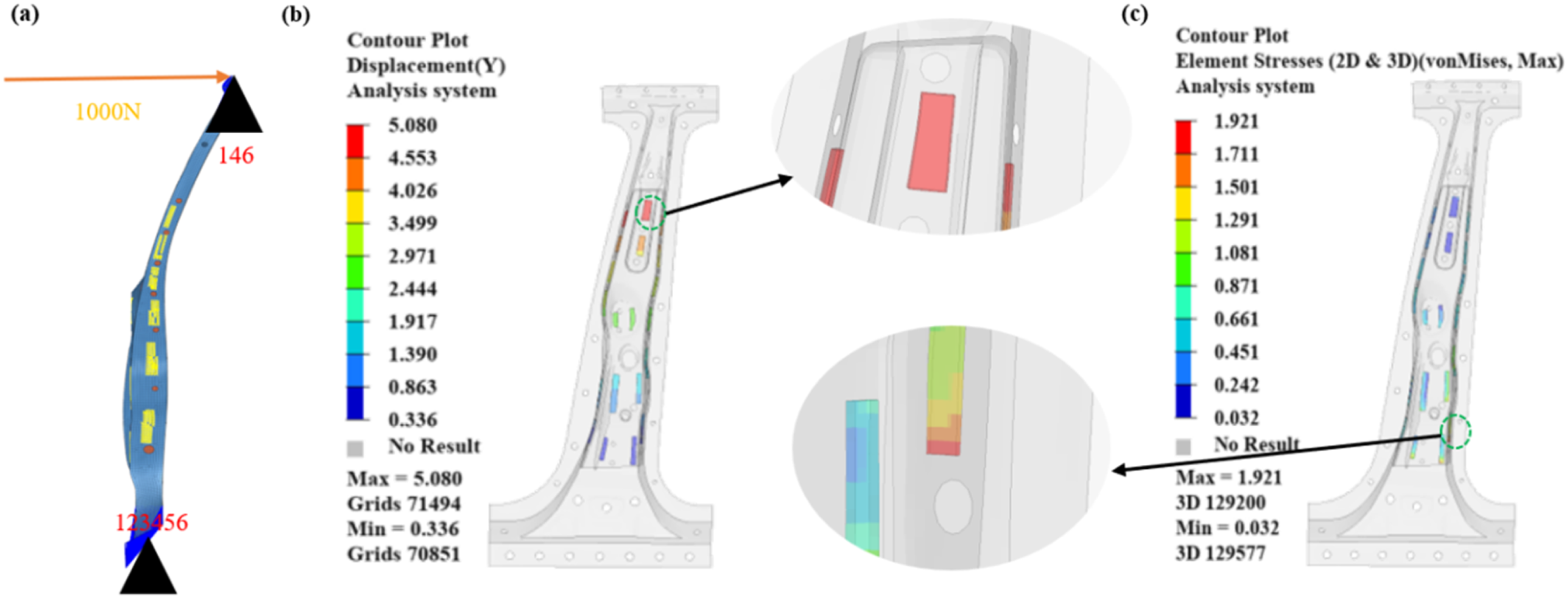
As shown in Figure 18(b) and 18(c), the displacement and stress contour plots for the adhesive bonding element in the hybrid material B-pillar assembly are presented. The maximum displacement in the Y-direction for the adhesive-bonded joint in the hybrid material B-pillar assembly is 5.08 mm, and the maximum stress is 1.921 MPa.
Rearward bending
To evaluate the ability of the adhesive bonding in the hybrid material B-pillar to withstand rearward bending forces during rear impact or rollover accidents, and to ensure that the adhesive bonding in the B-pillar maintain structural integrity, reduce deformation, and protect occupant safety in these situations, a finite element simulation model for rearward bending of the B-pillar assembly is established. The boundary conditions and loading setup for the hybrid material B-pillar assembly are shown in Figure 19(a). Table 11 presents the mechanical performance of the adhesive joints under four different working conditions. (1) Constraints: The translational degree of freedom along the Y-axis and the rotational degrees of freedom around the XZ-axes are constrained at the top of the hybrid material B-pillar assembly. The translational and rotational degrees of freedom along the XYZ-axes are constrained at the bottom of the hybrid material B-pillar assembly. (2) Loading: An RBE2 element is used to connect all upper nodes to a single point at the top of the hybrid material B-pillar assembly. A force of 10,000 N in the positive X-axis direction is applied at this point. Rearward bending working condition: (a) Constraints and load; (b) Displacement contour plot; (c) Stress contour plot. Mechanical performance of adhesive-bonded joint under four different working conditions.


As shown in Figure 19(b) and 19(c), the displacement and stress contour plots for the adhesive bonding element in the hybrid material B-pillar assembly are presented. The maximum displacement in the X-direction for the adhesive-bonded joint in the hybrid material B-pillar assembly is 3.69 mm, and the maximum stress is 7.776 MPa.
Based on the above simulation analysis, the adhesive bonding of dissimilar materials exhibit relatively small deformation and stress values under all four working conditions. To further validate the accuracy and reliability of the adhesive bonding simulation model, subsequent test verification of the hybrid material B-pillar adhesive bonding assembly is required.
Formation and test verification of hybrid material adhesive B-Pillar assembly
To further validate the mechanical performance and correctness of the finite element model of the adhesive bonding method proposed in this paper, a hybrid material adhesive bonding B-pillar assembly is fabricated, and a finite element model of the hybrid material adhesive bonding B-pillar assembly is constructed based on the stacking sequence.
Fabrication and simulation of hybrid material B-Pillar assembly
According to the [45/−45/45/−45/0/90/45/−45/0/90/45/−45/0/90/45/−45/0/90/45/−45/0/90/45/−45/0/45/−45/0/45/−45/0] stacking sequence, the carbon fiber composite B-pillar inner panel is layered and fabricated. It is then adhesively bonded to the steel outer panel to form the hybrid material B-pillar assembly, as shown in Figure 20. The same stacking sequence is applied to the simulation model of the carbon fiber composite B-pillar inner panel to establish the finite element model of the hybrid material adhesive bonding B-pillar assembly, as shown in Figure 21. Formation of hybrid material adhesive bonding B-pillar assembly. Finite element simulation of hybrid material adhesive bonding B-pillar assembly.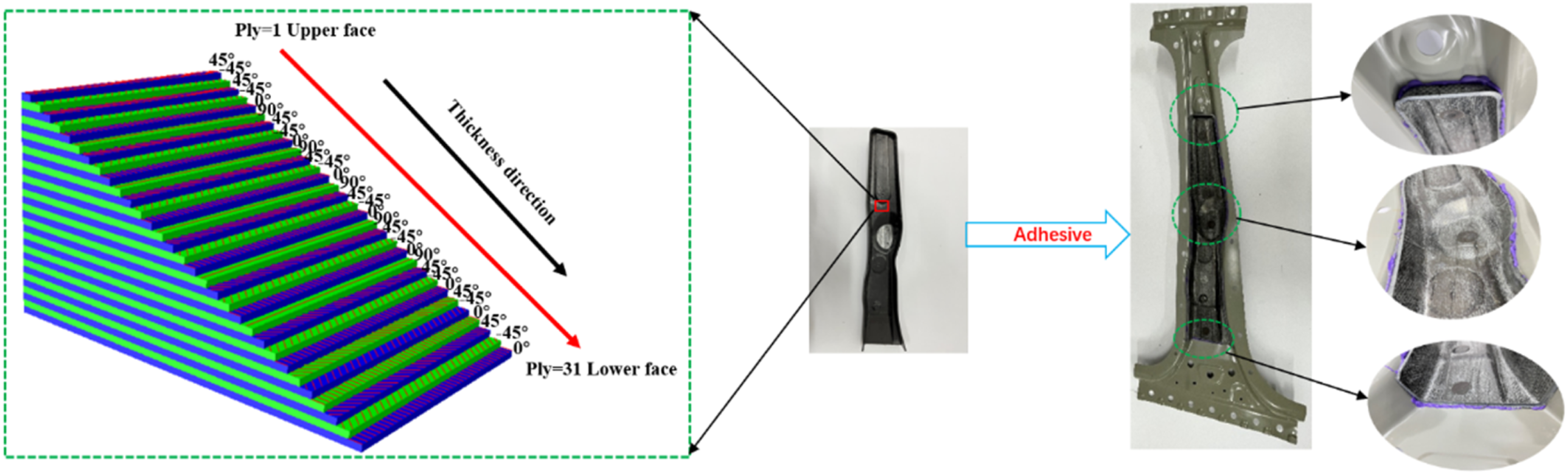

Three-point bending working condition simulation and test validation
Simulation and test are conducted on the B-pillar assembly with identical boundary conditions for both: the translational degrees of freedom along the XY-axes and the rotational degrees of freedom along the YZ-axes at the upper and lower ends of the B-pillar assembly are constrained, and a uniform load of 10,000 N is applied to the middle region of the B-pillar assembly. As shown in Figure 22, five measurement points (35,725, 47,590, 57,583, 58,571, 22,733) are selected on the B-pillar assembly, corresponding sequentially to positions “1,” “2,” “3,” “4,” and “5” in Table 12. The maximum error between the simulation and test occurs at position “4,” where the maximum simulated stress is 183.569 MPa and the maximum test stress is 189.256 MPa, resulting in an error of 3%. The second largest error occurred at position “2,” where the maximum simulated displacement is 24.704 mm and the maximum test displacement is 23.998 mm, with an error of 2.94%. The errors are within the acceptable accuracy of the model. Comparison of three-point bending test and simulation. Comparison of maximum displacement and stress results at measurement points under three-point bending working conditions.

Through the three-point bending test, the reliability and accuracy of the finite element model for the adhesive bonding of the hybrid material B-pillar assembly are validated. Furthermore, the feasibility and reliability of the adhesive bonding simulation method and strength analysis for the steel and CFRP dissimilar materials proposed in this study are demonstrated.
Conclusion
This study investigates the mechanical properties of metal steel and CFRP substrates, and obtains the corresponding material parameters. The adhesive performance of dissimilar materials was tested, and the mechanical properties of the adhesive layer are determined. Based on this, a finite element model for the adhesive bonding of dissimilar materials is developed. Simulations are conducted for both lap and butt adhesive-bonded joints, with the results validated against test data. The results demonstrate that the finite element models for both types of adhesive-bonded joints exhibit high accuracy. To further validate the bonding strength and the reliability of the simulation model, a finite element analysis of the mechanical performance of a hybrid material adhesive-bonded B-pillar assembly is conducted under real-world conditions, followed by a three-point bending test. The simulation results are generally consistent with the test data, confirming the feasibility and reliability of the proposed simulation method and strength analysis for the adhesive bonding of steel and CFRP. (1) The strength of the steel-CFRP adhesive bonding and its simulation analysis method are investigated and validated on an automotive hybrid material B-pillar. The results show that the deformation and stress values of the adhesive bonding are relatively small, providing a theoretical basis for the reliable bonding of dissimilar materials. (2) The q-stress damage initiation criterion of steel-carbon fiber reinforced composites is established by fitting the experimental data, and embedded in CZM using VUMAT subroutine. The feasibility of the performance prediction method is demonstrated by comparing the simulation analysis of the bonded structure of the modified constitutive model with the experimental results. (3) The strength of the adhesive finite element model is analyzed. Adhesive bonding simulations for the automotive steel-CFRP hybrid B-pillar are conducted. Based on the performance requirements of the B-pillar, simulations are performed under four different working conditions: axial tension, axial compression, lateral bending, and rearward bending. The simulation results show that under these four conditions, the maximum displacements of the adhesive elements are 0.401 mm, 0.401 mm, 5.08 mm, and 3.69 mm, and the maximum stresses are 5.332 MPa, 5.332 MPa, 1.921 MPa, and 7.776 MPa, respectively. These results indicate that the adhesive elements exhibit good strength under all working conditions. (4) Three-point bending simulations and tests verification are conducted for the hybrid material adhesive B-pillar assembly. Based on the [45/−45/45/−45/0/90/45/−45/0/90/45/−45/0/90/45/−45/0/90/45/−45/0/90/45/−45/0/45/−45/0/45/−45/0] stacking sequence, the inner panel of the automotive B-pillar is fabricated and simulated, and adhesive bonding is applied to bond it with the outer panel. In the three-point bending tests and simulations, the maximum stress and displacement error at five measurement points is 3%, validating the reliability and accuracy of the adhesive finite element model for the hybrid material adhesive B-pillar assembly. The results demonstrate the feasibility and reliability of the proposed simulation method for adhesive bonding between steel and CFRP dissimilar materials, as well as the strength analysis approach.
Footnotes
Author Contributions
Funding
The authors disclosed receipt of the following financial support for the research, authorship, and/or publication of this article: This work was supported by the Open Project of National Key Laboratory of Land and Air Based Information Perception and Control, China (No.B324009); Key Research and Development Project of Henan Province (241111241800); Open Fund Project of State Key Laboratory of Structural Analysis, Optimization and CAE Software for Industrial Equipment (GZ2024A03-ZZU); National Natural Science Foundation of China (52202437and52302408).
Declaration of conflicting interests
The authors declared no potential conflicts of interest with respect to the research, authorship, and/or publication of this article.
Data Availability Statement
The data that support the findings of this study are available from the corresponding author upon reasonable request.