
Abstract
Numerous studies have investigated polymeric composites fabricated using fused deposition modelling. However, the mechanical performance of these composites, which is influenced by various factors, including materials and printing parameters, remains unknown. Further understanding these factors helps improve the accuracy of mechanical performance predictions. Therefore, this study fabricates in-house polyamide reinforced with carbon fibre at a composition of 20 wt.% and controls its printing parameters, including layer height and printing orientations. Results indicated that controlling the orientation at a 0° angle are the most crucial factor compared to layer height, which leads to a maximum flexural strength of ∼21 MPa due to improvements in load-bearing capacity and adhesion bonding between the fibre and matrix.
Introduction
Fused deposition modelling (FDM) is one of the most widely used processes in additive manufacturing. Previous studies have mostly focused on polymer materials that are commercialised in the form of filaments. 1 However, innovation requires the use of polymer composites,2,3 and the current conventional polymer composites are fabricated with a low amount of filler composition of less than 15 wt.%, 4 thus compromising the mechanical performance of polymetric composites. To address this issue, previous studies have increased the amount of filler compositions to 20 wt.% or 40 wt.%. However, several problems persist, including unsettled printing parameters and poor interfacial bonding within printed polymeric composites.5,6
The differences in the printing parameters of materials can affect their mechanical performance. 7 Prior studies have highlighted that printing height significantly influences mechanical performance by triggering load-bearing effects when the materials solidify.8,9 As the layer height increases beyond 0.3 mm, the materials start to show voids and delamination 10 because the adjacent layer requires a long time to solidify as the amount of material increases during extrusion. This phenomenon offsets and warps the geometrical shape of the printed samples. However, different issues arise when the layer height is too low at around 0.1 mm. With less materials extruded from the nozzles, poor interfacial bonding is observed between the filler and matrix.10,11 The amount of filler should be limited given that only a small amount of such filler passes through the nozzle, thus contributing to the low load-bearing capacity as the printed layers are stacked together. Those samples experiencing low load-bearing capacity will subsequently lead to poor adhesion amongst layup sequences, thus diminishing the mechanical performance.9,12
Although layer height has a significant impact on mechanical properties, enabling the printed samples to operate at high temperatures is often considered a major drawback of composite materials. Some studies show that the mechanical performance drops by approximately 60% as the operating temperature exceeds room temperature.13,14 Therefore, maintaining mechanical performance at par with room temperature is crucial. By contrast, studies that use polyamide-reinforced carbon fibres (PACF) in high-temperature conditions reveal that the flexural strength reaches approximately 59 MPa, 5 thereby suggesting that adjusting the printing parameters with the optimum filler compositions allows the mechanical strength to rise up to ∼20% of the pure polymer strength (50 MPa). 15 Another study also highlights the importance of a post-printing drying process in enhancing the adhesion between printed layers.16,17
By reviewing the approaches for strengthening printed polymeric composites, a previous study shows that printing orientation can increase impact strength by up to 313% when using polymeric composite materials. 18 In a similar approach, a 0° orientation improves the tensile properties of PACF materials by 50%, but this improvement deteriorates as the build plate temperature increases to 105°C. 19 In other words, even when adjusting the printing orientation, the mechanical performance remains subject to the effects of materials and other factors, especially when these materials are intended for use in high-temperature conditions. Notably, numerous factors affect the final mechanical performance of printed parts, but adjusting fibre orientation significantly influences their mechanical strength, especially under high-temperature conditions. While printed parts are often used at room temperature, certain applications, such as robotics and biomedical fields, can be extended to 4D printing. This is what makes high-temperature studies crucial.
Notably, short carbon fibres are often used to produce valuable composites due to their impact on improving filament flow dynamics and consolidation, which enhances print uniformity and mechanical properties. 20 Whereas optimised the printing parameters, such as nozzle temperature and flow rates, improved bed adhesion and print quality by obtaining excellent bonding within adhesive layers. Meanwhile, challenges like fibre agglomeration limiting mechanical performance at higher fibre content 21 With a growing emphasis on sustainability, the research explored recycling technologies using thermoplastic matrix resins, which are easier to recycle compared to thermosets.21,22 By producing polymeric composites filaments compatible with standard 3D printing systems, the mechanical properties were assessed across varying fibre volume fractions.20,23 This approach provides a viable solution for recycling composite waste while retaining the mechanical advantages of fibre-reinforced polymers, contributing to more sustainable practices in industries like wind turbine and drone manufacturing. 20
In response to prior studies that highlight the importance of printing parameters and orientation in enabling the operation of materials at high temperatures, this study explores the effects of these parameters on mechanical performance. Notably, the fabrication of in-house filaments that allow materials to align in a specific orientation is crucial. This mechanism leverages the advantages of nozzle design, enabling fibres to align during the extrusion process. These compositions can vary up to a maximum of 20 wt.% while maintaining performance for high-temperature applications. This study aims to provide a better understanding and further insights into using in-house fabricated filaments for such applications. Therefore, the filaments are fabricated in-house, adjusted to a composition of 20 wt.%, and used to predict mechanical performance as the composition increases. The study is expected to show improvements in mechanical performance as the fibres align at a 0° angle, enhancing the load-bearing capacity of the printed samples and the adhesion bonding between the fibres and the matrix.
Methodology
Material
The filament compound was fabricated using grade CFP-7-50 carbon fibre (CF) prepared in powder form as filler. This filler was manufactured by Shenzhen Yataida High-Tech. Co. Ltd. (Shenzhen, China) and supplied by Sigma Aldrich Sdn Bhd. The short carbon fibre (CF) has an average diameter of 9 µm, length of 100 µm to 300 µm, density of 1.75 g/cm3 and aspect ratio of 43. As for the polymer resin, polyamide (PA) grade PA2200 was supplied by Sigma Aldrich Sdn. Bhd. The PA with a density of 0.45 g/cm3 was incorporated with CF as a binder in the filament-making process. Prior studies using a similar grade have reported the tensile modulus and tensile strength of this CF at 1620 MPa and 48 MPa, respectively. 24
Printability of polymeric composites
The composite materials (polyamide-reinforced CF, PA/CF) were pre-mixed into two sets with 20 wt.% of CF using a mechanical mixer (IKA RW20 WERK digital) at a rotational speed of 300 r/min for 3 to 4 min until the compound materials became homogeneous.25,26 Afterwards, the prepared PACF compound was fabricated into filament form using a 3Devo filament maker. The temperature was 190°C, the extruder speed was 5 r/min and the filament diameter was 1.75 mm (nozzle diameter) as reported in a prior study.
24
The Funmat HT printer with an FDM technique was used to print the samples.
5
The printing temperature was set at 230°C, the bed temperature was maintained from 90°C to 110°C, the printing speed was adjusted to 50 mm/s and the layer height was set at 0.2 mm. Notably, there are challenges involved during the printing process, particularly in fabricating the filament. During filament fabrication, the compounded materials need to be dried for a minimum of 5 h before they can be extruded using a filament maker. This ensures a smooth surface and prevents the formation of bubbles due to high moisture content. Once the filament is successfully fabricated using this drying technique, the printability of the materials reaches its optimal level. The detailed process is shown in Figure 1. The filament making and 3D printing process.
Measurement of thermal properties
The thermal behaviour, dynamic mechanical properties and viscoelasticity were determined through thermogravimetric analysis and differential scanning calorimetry. Both analyses were performed using a Mettler Toledo machine. All the information should be available before fabricating the filament and printing the samples to provide detailed parameters for these processes. The temperature range was set between 30°C and 900°C, with a temperature rate increase of 20°C/min in a nitrogen environment following ASTM E1131-98. The analyses were performed on printed samples at different orientation angles (0° and 90°) and on PACF composites at different layer heights (denoted by A1: 0.1 mm, A2: 0.2 mm and B1: 0.3 mm).
Morphology and structure analysis
The interfacial bonding of PACF composites, especially on the fracture cross sections, was examined via physical analysis by using a scanning electron microscope (SEM, model Quanta FEI, Quanta 400F). Given that the PACF samples are unconductive, they were coated with gold using a sputter coater (model Polaron Quorum Q150R) to capture excellent micrograph images. The imaging conditions were optimised with an accelerating voltage of 20 kV to ensure detailed surface observations given that low accelerating voltages would increase sensitivity to surface details, including the topography and morphological characteristics of the samples.
Mechanical testing of structure materials
To assess the mechanical performance of the structural materials, the Izod pendulum impact test (ASTM D256-19) was conducted with an energy value of 50 J. The samples were tested under different temperature conditions (30°C, 40°C and 50°C), and 10 tests were carried out for each sample set. To assess the shear properties of the PACF composites at 0°, 45° and 90° orientation angles, the deformation resistance of the material when subjected to a force parallel to its surface was analysed via a lap shear strength test (ASTM D3163-01). The samples were printed with an overlapping length of 25.4 mm. The universal testing machine (UTM, model Instron 5567) was initially employed with a crosshead displacement rate of 1.3 mm/min in room temperature. The test conditions involved single-piece samples with a load capacity of 30 kN as proposed in a previous study. 24 The mechanical characteristics of the PACF composites were then assessed by performing tensile testing (ASTM D638-03) with a crosshead speed of 5 mm/min on UTM (UTM, model Instron 5567). These tests were conducted under diverse printing conditions (0°, 45° and 90°) and temperatures (30°C, 35°C, 40°C, 50°C, 75°C, 110°C, 190°C and 200°C), along with an additional set of samples with different layer heights (0.1, 0.2 and 0.3 mm). Using a similar approach, a flexural test was conducted following ASTM D790, with a speed rate of 1 mm·min⁻1 and support span of 72 mm. These tests were carried out under various printing conditions (0° and 90°) along with an extra set of samples with different layer heights (0.1, 0.2 and 0.3 mm). The compression test was carried out in accordance with ASTM D3410 by using the Instron 5567 UTM. This test was conducted at printing orientations 0° and 90°. The densification of the PACF composites was assessed following the guidelines outlined in ASTM D792. A standard level balance, specifically the Mettler Toledo ME-T analytical balance, was employed, with distilled water having a density of 0.998 g/cm³. The primary objective of these tests was to evaluate the potential changes in the composite properties under different testing conditions, specifically at temperatures of 30°C, 75°C and 110°C.
Result and discussions
Effects of thermal degradations at various printing conditions
The materials fabricated in this study were limited to 20 wt.% due to the fact that materials above this threshold typically experience delamination, caused by high surface roughness. Prior studies have reported that the high surface roughness is due to the increased amount of fibre, which tends to experience pull-out during filament fabrication, resulting in poor adhesion during printing.
27
On the other hand, compositions below 20 wt.% are often associated with minimal improvements in mechanical performance. Conventional filaments typically use 15 wt.%, allowing researchers to optimise the composition up to a maximum of 20 wt.%. The results demonstrate the importance of investigating thermogravimetric properties, particularly for identifying temperature variations before and after the materials are printed and assessing their ability to withstand external temperatures. Figure 2 shows no huge differences between the orientation angles of 0° and 90° but reveals significant differences amongst printed samples with varying layer heights. Specifically, at ∼410°C, a substantial 40% difference was recorded between orientation angles and layer height, which suggests that at a layer height of 0.3 mm, the materials easily deteriorate as the gap amongst the layer heights increases.10,28 Study on different layer height using PLA indicated that it has significant affected towards temperature difference compared to ABS materials.
28
Thermogravimetric analysis of PACF at different printing orientations (0° and 90°) and layer heights (denoted by A1: 0.1 mm, A2: 0.2 mm and B1: 0.3 mm).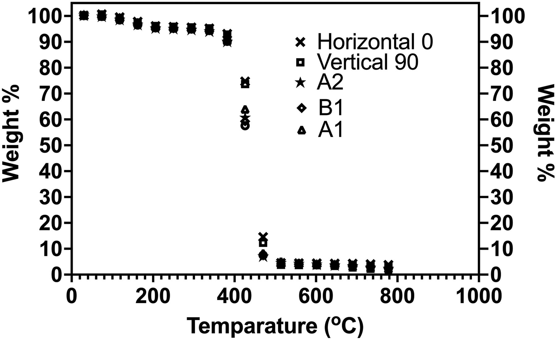
Effects on mechanical performance at various printing conditions
A study on additive manufacturing and characterisation of PLA reveals that PLA exhibits the highest strength with no discernible dependence on layer height [7]. However, this study does not directly address temperature differences amongst materials. Figure 4(a) illustrates the effects of temperature on various printing conditions. At a 0° orientation, tensile strength increased almost fourfold compared with the other sample conditions, reaching 3.3 MPa. At this orientation, the applied load was distributed along the fibre longitudinal directions, thereby maximising the strength before the samples collapsed. By contrast, at a 90° orientation, the samples printed in vertical or lateral directions caused the minimum load to be carried by the fibres, thus easily introducing gaps when the load was applied. Consequently, the results were on par with those obtained in the other sample conditions at high temperatures. A prior study has attributed such result to the consideration of the load-bearing process during printing, which has a significant impact on mechanical performance. 9 Specifically, this study suggests that printing in the vertical direction will improve the adhesion bonding between the resin and filler, thus increasing tensile strength. 8 The tensile strength doubled from 0.3 MPa to 1.02 MPa as the temperature increased to 110°C in the data recorded at various temperatures. Below the water removal region (Figure 2), the heat allowed the printed layer materials to soften, thereby filling the voids between the laps and increasing interfacial bonding. The results in Figure 4(a) are similar to those of a prior study showing that the tensile strength of polymeric composite materials tends to deteriorate as the temperature rises. 29
Results of the tensile test suggest that the mechanical performance significantly declines as the temperature rises. Therefore, a flexural test was conducted at different orientation angles (0°, 45° and 90°) and layer thicknesses (0.1, 0.2 and 0.3 mm). The layer thickness directly reflects the gaps amongst the printed layup materials.
30
Figure 4(b) shows that the flexural strength at the 0° orientation angle peaks at 21.8 MPa and only reaches 20 MPa at a 45° orientation angle. These data indicate that the results for the 0° and 45° orientation angles are comparable, with a layer thickness of 0.2 mm and an average flexural strength of 20 MPa. Nevertheless, the maximum recorded flexural strength for individual samples reached 27.4 MPa at a 0.2 mm layer thickness, thereby suggesting that controlling the layer thickness will have similar load-bearing effects on the samples, which was previously observed when the samples were aligned at a 0° orientation angle as shown in Figure 3. Whilst layer thickness exerts a significant influence on the strength of the PACF, varying the layer thickness attributes leads to different performance strengths.
31
Theoretically, the weakest point lies in the Z-axis primarily due to the inadequate bonding amongst the layer sequences (Figure 3).
32
Consequently, an increase in layer thickness beyond 0.2 mm reduces the heat transfer to the layer below, thus leading to suboptimal interfacial bonding. A similar phenomenon is depicted in Figure 4(b) where, when the layer thickness increased to 0.3 mm, the strength dropped by nearly 20%. Conversely, when the thickness was reduced to 0.1 mm, the PACF became prone to high shear stress induced by the principal plane as the compressive stress diminished (thus minimising the contact area within the extruded materials).
33
A previous study shows that when the temperature exceeds 75% of the nozzle size, the filament tends to collapse, thus resulting in printing failure.
34
This observation suggests that the optimal layer height should not exceed 0.25 mm.
33
Micrograph images of fracture samples (cross section view) for the tensile, shear and compression tests at various temperature conditions and printing orientations. Mechanical performance of PACF, including (a) tensile strength, (b) flexural strength, (c) shear strength, (d) shear modulus and (e) compression strength, under various factors, such as orientation, operating temperature and layer height.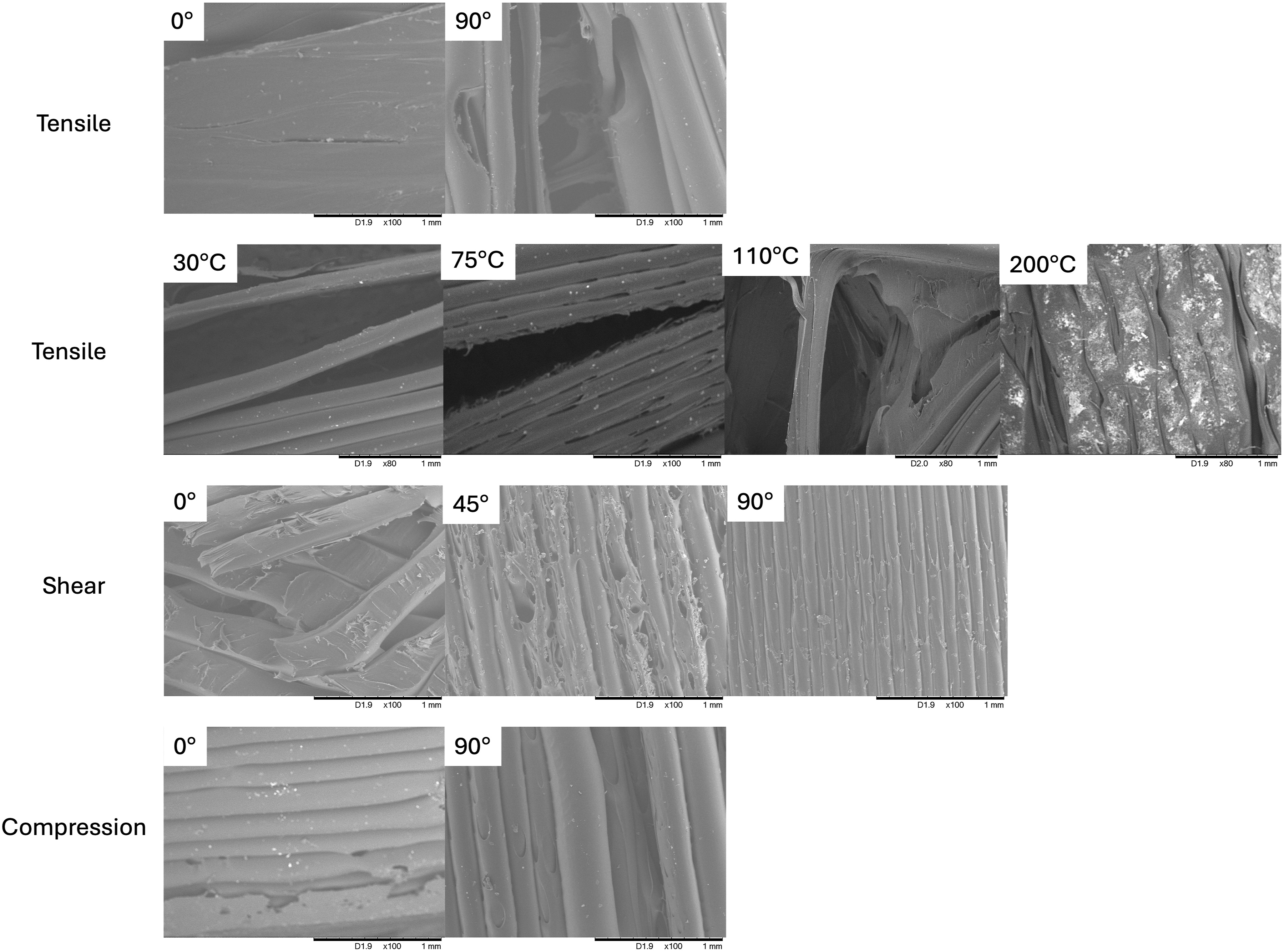

The impact of orientation on shear stress was then examined at angles of 0°, 90° and 45°. The results in Figure 4(c) contradict those of the tensile and flexural tests. The highest shear stress (0.4 MPa) was recorded for the 90° orientation angle, whilst the lowest (0.18 MPa) was recorded for the 0° orientation angle. This contrasting finding could be primarily attributed to the impact of the orientations of the printed PACF on shear strength. When load was applied in the horizontal direction (90°), more strength is required to separate the bonding between the fibre and matrix owing to the effective adhesion bonding when load is applied in parallel. However, at a 0° orientation angle, the applied load was perpendicular, thus requiring less force to break the bonding between the fibre and matrix. Similar findings were recorded using polypropylene-glass fibres, where the enhanced fibre and matrix orientation improved the tensile performance along the flow direction. 35 Although previous studies show that orientation affects the shear performance of printed samples, another study reports that apart from orientation, an increase in temperature (introduced using the laser heating technique) also affects the interlayer strength of printed samples, thus yielding significant results in shear strength.33,36 A similar trend was recorded for the shear modulus in Figure 4(d), with the highest value of 245 MPa being observed for the 90° orientation angle. The samples with a 90° orientation angle showed high resistance to transverse deformations, consequently increasing rigidity. This observation aligns with the results for the tensile and flexural strengths of PACF composites. Meanwhile, a study on carbon fibre-thermoplastic materials printed at a 90° orientation angle (referred to as on-edge orientation) reveals a superior shear modulus compared with materials printed at a flat orientation (45° orientation angle) 37 due to the presence of contour layers in flat printed samples, which prevent premature failure at the notch or edge region and result in a high shear strength for the flat printed samples.37,38
The results for compression strength exhibit a similar behaviour, with strength increasing (∼130%) as the printing path aligns parallel to the loading direction. 39 This result is attributed to the fact that the 0° orientation angle demonstrated approximately 51% higher compression strength at 33 MPa compared with that at the 90° orientation angle, which only registered 16 MPa as shown in Figure 4(e). Compression strength tends to be lower than tensile strength. However, Figures 4(a) and (e) reveal a significant difference of approximately 91% in this regard because the application of compression load minimises warping buckling and delamination occurrences given that the samples were prepared at 100% density as the bulk samples. A previous study shows that increasing the infill density also improves the compression strength of the materials.40,41 Additionally, the interlayer within the fibre-matrix surface improves when the orientation is controlled at 0°, leading to excellent adhesion bonding within the printed layer. 42 These factors explain why the compression strength is higher than the tensile strength.
According to the mechanical strength performance of the printed PACF, a dedicated orientation at a 0° angle yields better results compared with various orientations and adjusting the layer height. Therefore, focussing on the 0° orientation angle, impact tests were performed on 12 sets of samples as illustrated in Figures 5(a) and (b). The impact test results indicate an average absorbed impact energy of 1.45 J or approximately 0.2 J/mm2. These results are slightly lower compared with that for polymer materials, such as acrylonitrile butadiene styrene (ABS), which typically record around 0.5 J/mm2 when printed using the FDM technique.
43
This phenomenon can be mainly attributed to the low filler content at 20 wt.% compared with the resin polyamide. Theoretically, the filler is expected to bear the load applied during the impact test, thereby significantly enhancing impact strength. Although various factors can influence the impact strength of printed polymeric composites, previous studies have revealed that increasing the layer height to 0.3 mm increases strength 3 times greater than setting the layer height at 0.1 mm.
18
The choice of polymer materials and printing direction can also result in variations in impact strength.
44
Printed PACF samples analysed under (a) absorbed impact energy and (b) average median of absorbed impact energy.
Conclusion
The PACF composite developed using FDM was analysed with respect to various factors, including orientation, high operating temperature and printing parameters (e.g., layer height). The analysis results confirm that printing orientation significantly affects mechanical performance and the adhesion and interfacial bonding amongst printed layers which detailed as follows: a) At 0° orientation angle, the flexural strength can peak at 21 MPa at a composition of 20 wt.% carbon fibre. These evidence that carbon fibre that orientated in 0° angle allowing better improvements in load-bearing capacity and adhesion bonding between the fibre and matrix. b) At high operating temperatures (110°C), the printed samples experienced a spike in their tensile strength, thereby suggesting that at a specific temperature, the re-melting of resin improves the adhesion and bonding between the fibre and matrix, thereby increasing its value.
Further investigations should be conducted at various compositions and materials to maximise mechanical performance.
Footnotes
Acknowledgements
The author would like to thank Kwek Kian Sheng, Nuraina Balqis Binti Zainal and Aniq Aiman bin Rosafandi for their efforts in conducting the analysis.
Declaration of conflicting interests
The author(s) declared no potential conflicts of interest with respect to the research, authorship, and/or publication of this article.
Funding
The author(s) disclosed receipt of the following financial support for the research, authorship, and/or publication of this article: The authors acknowledge the Fundamental Research Grant Scheme (FRGS), grant number FRGS/1/2024/TK10/UKM/02/3, funded by the Ministry of Higher Education (MOHE), Malaysia, and the part of this research is supported by the Faculty of Engineering and Build Environment & Centre for Research and Instrumentation Management (CRIM), Universiti Kebangsaan Malaysia, grant number Dana Pecutan Penerbitan FKAB.