
Abstract
With the rise in carbon fiber-reinforced plastic (CFRP) usage, there is a growing occurrence of waste disposal, prompting the exploration of different recycling methods. The primary methods of recycling include separating carbon fibers and resin from discarded CFRP products or reusing scraps generated during CFRP production, such as dry fabric or prepreg. Recycling leftover dry fabric is essential for waste management in the automotive industry. Current research is centered on utilizing recycled materials to produce anisotropic mats, presenting difficulties in managing variations in properties. Moreover, isotropic mats are the preferred choice for practical automotive component design. Our research aimed to solve this problem by creating recycled carbon fiber (rCF) mats with isotropic characteristics through a wet method to enhance even fiber spreading. Conditions to minimize property changes in the fabric based on direction were identified, and the mats were tailored accordingly. Then, the resin was impregnated into the mats using compression resin transfer molding to form CFRP. The static properties of the CFRP specimens produced were evaluated to identify conditions that maximize isotropy. Furthermore, observations of oil injection into rCF mats showed that resin track formation was reduced when CFRP was fabricated using isotropic mats.
Introduction
The use of carbon fiber-reinforced plastics (CFRP) has generated a great interest in recent years, as they are applied to the design of lightweight products to replace conventional materials (i.e., steel, aluminum, and alloys), despite their high cost.1–4 The increase in the amount of carbon fiber is due to the physicochemical properties of ultra-stiffness, low density, excellent thermal and electrical conductivity, and high thermal and chemical stability while being very lightweight. 5 Carbon fibers are commonly used to reinforce composites due to their high strength-to-weight ratios. They are now widely used in the transportation and high-technology industries as well as building materials.6–8 The global demand for carbon fiber is expected to reach 117 kilotons (kt) and 194 kilotons (kt) for CFRP in 2022, representing compound annual growth rates (CAGRs) of approximately 11.50% and 11.98%, respectively, compared with 2010. 9 In recent years, the automobile industry has demanded a plan to significantly improve fuel efficiency through body weight reduction to meet the increasing demands for electronic, high-end, and consumer safety. Nonferrous metals, such as aluminum alloys, have been mainly used as materials for weight reduction of automobile bodies; however, general polymer materials and polymer composite materials with appropriately reinforced strength are widely used as weight reduction materials. Among these, the role of carbon fiber-reinforced composite materials in the weight reduction and safety of automobiles is expected to increase. 10
However, the increased use of carbon fibers generates considerable waste, which has become a global issue.11,12 Large amounts of CFRP waste are currently being landfilled or incinerated. This raises the urgency of developing economically sustainable waste management and recycling technologies for CFRP.13,14 The main waste produced in the process of making CFRP is disposed of products made of carbon fiber and resin. These products are typically discarded because of flaws or reaching the end of their lifespan. Moreover, scrap materials are generated when making CFRP with prepreg or dry fabric, and is later shaped by cutting.
The advantages of carbon fiber recycling include the following: First, recycling not only reduces the amount of CFRP or carbon fiber thrown away after use, but it can also be a fiber supply solution that meets future demand. 15 Second, it can reduce the energy intensity required for carbon fiber manufacturing and can have a positive impact on the environment and human health because of the various pollutants emitted by oxidation and carbonization furnaces by bypassing several production steps.16–18
It is estimated that 30% of the total material used to manufacture carbon fiber parts is wasted, mostly in the form of scrap prepreg or scrap dry fabric.19,20 However, if discarded carbon fiber is recycled, it can be used at approximately 33% of the cost of virgin fiber, typically owing to a 10-fold reduction in manufacturing energy. 21 Accordingly, the utilization of recycled carbon fiber (rCF) composite materials is expected to increase in the automobile industry because rCF can provide excellent surface properties and is lightweight. 22 The CFRP recycling process is divided into two steps: reclaiming carbon fibers from CFRP waste (i.e., extracting rCF from CFRP waste) and producing an rCF-reinforced polymer (rCFRP) (i.e., using rCF to manufacture CFRP). 23
Short regenerated carbon fibers are produced through the shredding process and can be reused in the production of non-woven materials and mats through the molding process. However, the processing time and cost of rCF are obstacles to its recycling.24,25 Therefore, it is important to recognize the method of reusing dry fabric pieces without having to separate the carbon fiber and resin. In most cases, fibers are cut into uniform sizes during the mat manufacturing process without undergoing any extra heat treatment. Nonetheless, the recycling of dry fabric scraps involves a straightforward heat treatment method to eliminate any impurities from the scrap collection process. Later, the scrap that has already been cut is processed again to create fibers of equal length, which are then used as raw material for mat manufacturing. There is a need to pay attention to methods that reuse dry fabric scrap, eliminating the necessity for separating carbon fibers and resin. Usually, when manufacturing mats, fibers are utilized as chopped fibers in a consistent size without any extra heat treatment. Nevertheless, a simple heat treatment procedure is needed to recycle dried fabric scraps to eliminate any impurities that may have been introduced during the collection of the scraps. Afterward, the already cut scraps are further processed into chopped fibers of uniform length and used as raw material for mat production. In addition, as a recent manufacturing trend, there is a method of making an anisotropic carbon mat by imparting directionality to the recycled mat; however, it is difficult to control the deviation of physical properties, making it challenging to design the required physical properties of parts used in automobiles. In the field of actual automotive parts design, isotropically manufactured mat is preferred; however, when using discontinuous fibers, it is mainly used for the production of auto parts that do not require large physical properties. 26 This is because there is less expectation for tensile strength or rigidity, and there is an ease of design that does not require the consideration of fiber anisotropy. However, deviations occur in the longitudinal (X-axis) and width (Y-axis) directions during mat production, even in isotropically produced mats. 27 As a result, not only are the physical properties different from those of the actual product when designing the product, but also the difference in impregnation speed during molding also causes a race track, which causes problems such as non-impregnation.
Two techniques for creating mats from regenerated non-woven fabrics are dry methods and wet methods. 28 The dry method forms a web by carding or air-laid method. The carding method orients the fibers in the machine direction by combing, and the air-laid method laminates the fibers by passing them through the air, so a directional mat is produced, while the wet method uses the wet-laid method to disperse the fibers in water to form a web. The wet process is superior to the dry process for creating carbon fiber mats with isotropic properties. 29 In addition, there is an advantage in improving the strength of non-woven fabrics and improving interfacial adhesion.
In general, existing rCFRP products are made by impregnating and curing resin, grinding and heat-treating to separate fibers and resin, and collecting regenerated fibers to make a mat. 30 This study aimed to achieve consistent physical characteristics of mat by addressing impurity and low dispersion issues found when recycling carbon fiber fabrics discarded during the HP-RTM process. In general, rCFRP parts using discontinuous fiber mats have the disadvantage of being difficult to form because anisotropy occurs in the carbon fiber and a race track occurs during part manufacturing. To the best of our knowledge, this is the first study of isotropic mat technology for automobiles to propose a method for preventing race tracks by minimizing the deviation of physical properties using regenerated carbon fibers. In this process, carbon fiber scrap remaining after production is reused before being impregnated with resin, so fiber damage can be minimized by simply thermal and mechanical treatment. A wet method was utilized in place of a dry method to enhance the bonding strength at the interface between resin and fiber after heat treatment, as well as to enhance the fiber’s dispersion capability. Simultaneously, the wet method also aimed to enhance the manufacturing of isotropic rCFRP with uniform strength by minimizing variation in fiber orientation during the production of recycled carbon fiber mats using anisotropic waste carbon fiber fabric via the wet method. This attempt was to secure economic feasibility by reusing carbon fiber fabrics discarded after production. In the future, preforms must be incorporated into the high-pressure resin transfer molding (HP-RTM) process to utilize the scrap generated during production effectively.
Materials and methods
Preparation of carbon fiber fabrics
To produce mats, woven fabrics (C-weave 245T) made of continuous fibers (Toray T700, 3K plain) were gathered and processed into chop fibers of consistent lengths (6 mm and 12 mm) through a cut crusher (Jisico Co., Ltd, Seoul, Korea). Scraps of carbon fiber fabrics were collected on-site as scraps remaining after being used in the CFRP plant. The limitation of the fiber length was determined based on the fact that when the fiber length exceeded 12 mm, the desired physical and surface properties deteriorated. When the fiber length was less than 6 mm, the physical properties deteriorated, and the work became difficult. A CNC machine (CNC-STEP GmbH & Co., Germany) was used to reduce the variation in the physical properties and to cut the fiber length precisely and regularly. The heating process was carried out in a heat treatment oven at a temperature of 500°C for 2 h to eliminate impurities from the chopped carbon fiber fabrics, followed by the application of a binder for preform manufacturing. Proper heat treatment is necessary due to the potential ingress of dust during scrap storage. While this may decrease interfacial adhesion between resin and fibers, it is essential for impurity removal and enhancing dispersion. The control sample is mat manufactured by cutting fibers in the form of a strand.
Pretreatment of rCF mat
To improve the dispersibility of the prepared carbon fiber fabrics in water, pretreatment was performed to minimize the hydrophobic groups on the surfaces of the carbon fiber fabrics. Carbon fiber fabrics and water were mixed in a ratio of 1:1 and then immersed for 10 min by adding 30% ethanol to the weight ratio (wt%) of the fiber fabrics. A surfactant was applied to disperse the fiber fabrics in deionized (DI) water. The dispersion solution was prepared by mixing 95% carbon fiber and 5% polyvinyl alcohol (Kuraray Euro GmbH Inc., Deutschland, Germany), followed by mixing with 99.7% of DI water. Five dispersion solutions were prepared to obtain fiber area weights (FAW) of 30 g/m2, 70 g/m2, 130 g/m2, 200 g/m2, and 300 g/m2. The most important factor for realizing isotropy in the wet method is the speed of the conveyor. Reducing the speed of the conveyor can enhance isotropic characteristics, but it also results in a reduction in productivity. Therefore, considering these factors, the choice was made to adjust the fiber areal weight (FAW) and fiber length rather than altering the conveyor speed to achieve isotropy.
After adding a 3% non-ionic surfactant (Sigma–Aldrich, Saint Louis, USA) based on the weight ratio (wt %) of the carbon fiber to the dispersion solution (Figure 1(a)), dissociation was performed at 1150 r/min for 5 min using a high-speed dissociator (Miltenyi Biotec Korea Co., Ltd, Seoul, South Korea). The conditions used in the experiment were selected based on a preliminary experiment, as shown in Figure 1. Subsequently, 0.8% carboxymethylcellulose (Korea CMC Ltd, Daejeon, South Korea) was added (Figure 1(b)) and stirred at 700 r/min for 10 min to prepare an aqueous solution (Figure 1(c)). Here, carbon fibers using nonionic surfactants tend to agglomerate again over time. To avoid this occurrence, carboxymethylcellulose was utilized. Following dispersion, dehydration took place as a carbon fiber web was created on the wire mesh. The wire meshes used in this study were 60–80 mesh, suitable for the carbon fiber diameter. Here, the mesh is a unit expressing the thinness of the wire and represents the number of holes in a square area of 1 inch × 1 inch. Generally, the higher the number, the finer the mesh. An infrared dryer and a floating dryer were used to dry the rCF mats. The appropriate temperatures at which the added binder material could be melted were set, but the temperature was sequentially increased to prevent aggregation of the binder. In this experiment, 30 min were maintained at 70°C, 20 min at 110°C, and 20 min at 130°C. In addition, moisture inside the chamber was discharged to facilitate drying. Preliminary tests for parameter selection. (a) Dispersibility according to the amount of dispersant added, (b) dispersibility according to carboxymethylcellulose, and (c) dispersibility according to mixing conditions. Fabrication of CFRP using rCF mat.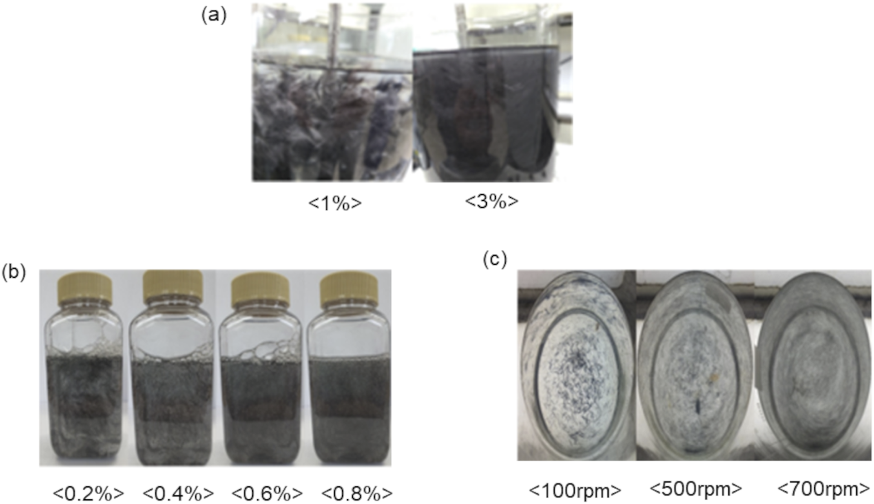
An epoxy resin (KFR-36002/KFH-36308, Kukdo Chemical) was injected into the flat mold using a dosing unit (Estrim-HP RTM, Cannon Plas Tec, Inc., Milan, Italy). While maintaining the pressing force, a molding operation was performed using a composite press (Schuler Smg GmbH & Co., Waghausel, Germany). The compression resin transfer molding (C-RTM) method was used to fabricate the CFRP. The physical properties of FAW 300 CFRP and FAW 30 CFRP were observed under different lamination conditions. After stacking three sheets of FAW 300 CFRP and 30 sheets of FAW 30 CFRP (for a meaningful comparison of properties, the materials must be manufactured with the same volume fraction [Vf]), the gap between the top and bottom was maintained at 1.5 m. The inside of the mold was maintained at 20 kPa using a vacuum pump. At this time, the mold was not completely closed and low pressure was maintained within the mold by sealing. The vacuum valve was closed, and epoxy resin was injected into the mold at a rate of 40 g/m2 through the resin inlet at the center of the mold using a resin injector. After the epoxy resin injection was finished, the mold was pressed at a speed of 0.1 mm/sec to impregnate and harden the resin. During molding, the pressure was maintained at 6000 kPa for 7 min, at which the mold temperature was 120°C. The target CFRP was 1.8 mm.
Measurement of physical properties and uncertainty
The physical properties and thicknesses of the fabricated rCF mats were measured. The CFRP specimens’ tensile, compressive, and flexural strengths were evaluated using a tensile strength tester (MTS System Co., Eden Prairie, USA) following the ASTM standards D3039, D6641, and D790. The thickness of the prepared rCF mat was measured according to the ASTM D1777 standard using a thickness meter (Mitutoyo, Kawasaki, Japan). The thickness of the CFRP made after injecting the epoxy resin was measured by TAPPI T411, the tensile strength by ASTM D-828, and the elongation by ASTM D-828.
Analyzing the absolute error, equivalent to experimental error, was conducted to assess the measurement uncertainty of the material constants obtained from the tensile test. Measurement uncertainty is a result of the measurement tool’s particular scale, leading to inaccuracies in measurement.31,32 When measuring a single quantity, interpreting the absolute error is straightforward. However, when measuring the size W, which is the sum of other approximate quantities Wn, problems may arise in the interpretation of the absolute error.

The total absolute error is the addition of the absolute errors from its separate parts.

While determining the absolute error, it is important to consider the compensation of partial errors with different signs, as shown in equation (3).

The absolute error value should be determined by taking into account the compensation for individual errors as explained in the previously provided relationship.31,32

Observation of resin flow with permeability coefficient
The coefficient of permeability was measured based on the flow of the resin into the oil on a flat plate. According to Darcy’s equation, the resin flow through the textile can be expressed by equation (1).
33

Sample preparation of checking resin direction deviation.

Comparison of molding analysis
To predict the resin flow during actual CFRP molding, the finite element method (FEM) was applied using resin transfer molding (RTM) simulation software (ESI Group, Paris, France). The results obtained by measuring the flow of the resin following the injection of oil on the flat plate were used as input values for the simulation. The resin viscosity data provided by the resin manufacturer were used as the physical property values for molding analysis. The molds used for the FEM and the actual mold design are shown in Figure 2. The dimensions of the mold used in the experiment were 400 mm × 400 mm × 2 mm, and the mold was molded for 7 min at 6000 KPa. The molding conditions were the same as those used for flat-plate manufacturing, as shown in Table 1. The difference in the impregnation pattern between the flat plate and the shape of the actual molded product was confirmed. Information on mold design for CFRP
Results and discussion
Manufacturing of rCF mats
Analysis of standard deviation using FAW and thickness on rCF mat.


Effect of FAW on rCF mat fabrication using 6 mm carbon fiber fabrics.
Physical properties of rCF mats
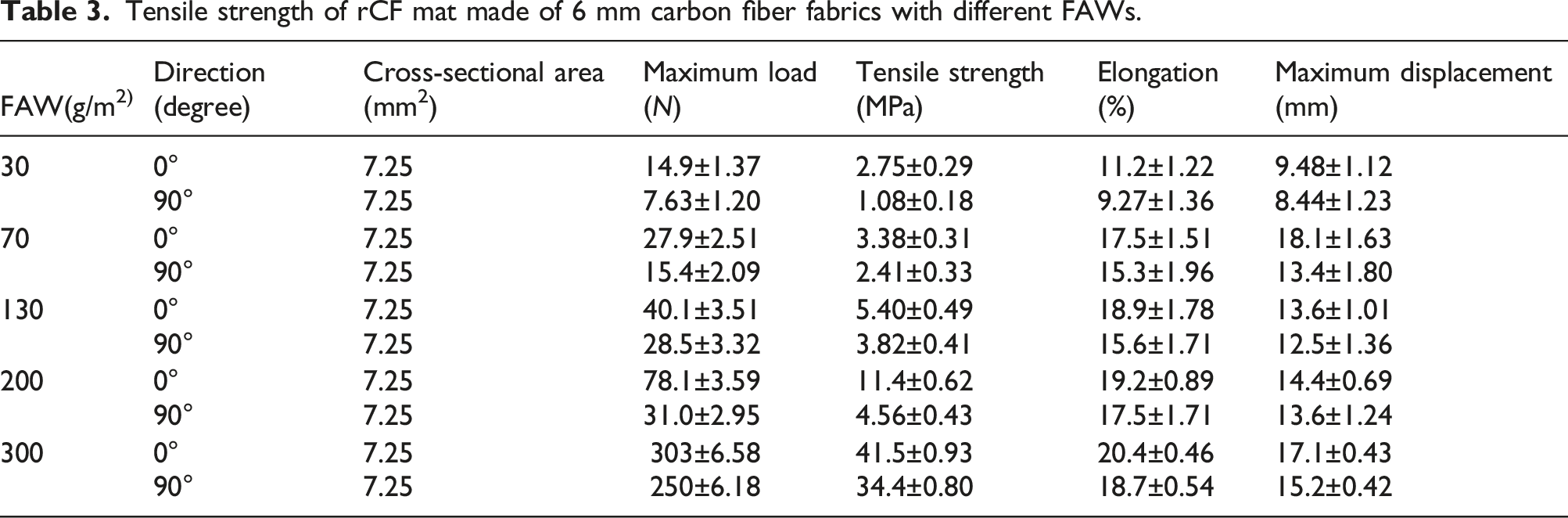
Tensile strength of rCF mat made of 6 mm carbon fiber fabrics with different FAWs.
Tensile strength analysis with rCF mat using 12 mm carbon fiber fabrics.

CFRP optimization considering physical properties
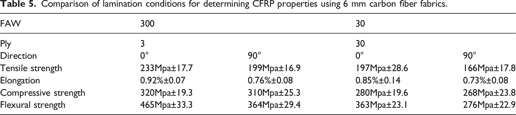
Comparison of lamination conditions for determining CFRP properties using 6 mm carbon fiber fabrics.
Resin flow and permeability coefficient
The results of measuring the flow of the silicone oil before injecting the resin are shown in Figure 4. The condition with the least deviation (i.e., rCF mat using 6 mm carbon fiber fabrics, 0° direction, and FAW 300 × 3ply) was applied. Because the resin impregnation spreads evenly along the X- and Y-axes in concentric circles, it can be inferred that there is no significant difference in the permeability coefficient in each direction. The moving speed of the resin over time was 0.7748 m/s. The permeability coefficient in the X-direction (K1) is slightly greater than that in the Y-direction (K2), but the discrepancy is not noteworthy based on the experimental data. The value of K1 obtained using Darcy’s law was 1.18e−09(standard deviation: 1.09e−10), and the value of K2 was 9.07e−10(standard deviation: 3.63e−11). Analysis of flow using silicon oil.
Analysis of RTM simulation and actual flow
As a result of comparing the results obtained using the casting simulation software by employing the permeability coefficient obtained using Darcy’s law, it was confirmed that there was almost no deviation in the X- and Y-axes. The simulation results are shown in Figure 5. It is expected that the experiments using these silicone oils are expected to yield similar results when manufacturing CFRP in its actual shapes. Prediction of resin flow pattern using simulation.
The potential for a race track on the resin flow was verified by monitoring its injection into the rCF mat. When fabricating the CFRP, 33%, 50%, and 66% of the epoxy resins required for the entire fabrication process were injected to observe the resin flow. In Figure 6, a concentric circle was drawn, and when the filling rate exceeded 50%, there was a minimal deviation between the X- and Y-axes, validating its similarity to the RTM simulation. The experiment showed that there was a noticeable difference in movement speed between the X-axis and Y-axis epoxy resin when the filling ratio was 33%. However, as the amount of resin increases, the deviation on the X-axis decreases, reducing the risk of a race track. Measurement of resin flow pattern during actual molding processes. (a) 33% filling rate, (b) 50% filling rate, and (c) 66% filling rate.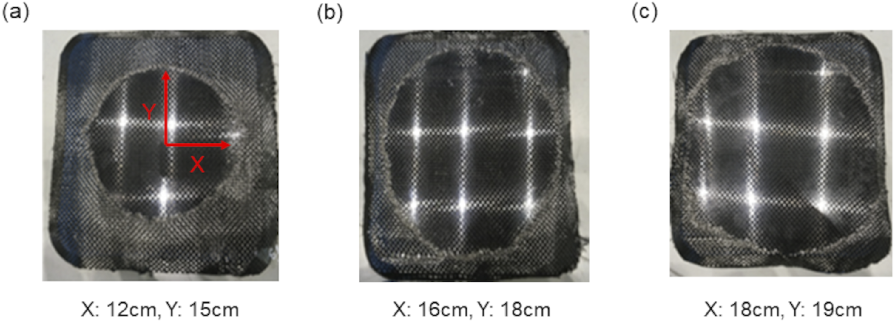
Conclusions
Waste scraps generated when producing carbon fiber fabric products are cut to a certain length and subjected to various treatments to produce CFRP. In anisotropic mats, non-impregnation may occur because of the difficulty in predicting the epoxy resin flow, as well as the control of the physical property deviation during CFRP product molding. Therefore, a method to reduce the deviation in physical properties that occurs during rCF mat manufacturing was identified and used in CFRP production. During the fabrication of the rCF mat, the deviation in the fiber orientation (i.e., 0° and 90°) was confirmed through the adjustment of the fiber length (i.e., 6 mm and 12 mm) and FAW to derive conditions with less deviation; the mat was produced under two conditions (i.e., FAW 300 and FAW 30). After molding the CFRP under these conditions, the physical properties such as tensile, compressive, and flexural strengths were observed. The possibility of a race track was confirmed by observing the flow of the resin while injecting it into the rCF mat. The following conclusions were drawn: 1) If the length of the carbon fiber fabrics was fixed at 6 mm and rCF mats with different FAWs were manufactured, the deviation between the X- and Y-axes decreased as the FAW increased. This is probably because the empty space is reduced as the amount of carbon fiber fabric increases. 2) The overall physical properties were improved by reducing the length of the carbon fiber fabrics from 12 mm to 6 mm. This occurs because when the fiber is longer, it is more probable for it to bend instead of being aligned in a specific direction, causing it to bend in a non-preferred orientation for the material. 3) The physical properties were evaluated by fabricating CFRP specimens with the same Vf as FAW 30 and FAW 300, and it was confirmed that the deviation in the physical properties was smaller in FAW 300. This indicates that it is difficult to compensate for defects occurring in the rCF mat even if the rCF mat is laminated in several layers. 4) It was confirmed that the multilayer lamination of the rCF mat made of FAW 300 with a carbon fiber length of 6 mm had little difference in the permeability coefficient in the X- and Y-directions. 5) Simulations for epoxy resin and molding analysis using rCF mat injection experiments were performed to obtain similar results for actual CFRP production. These results may reduce the probability of non-impregnation in actual CFRP production and minimize the resulting race track. 6) The sample obtained through the procedure exhibited physical properties that were 85%–90% similar to those of the control sample.
Footnotes
Author contributions
M.Y.: Methodology and formal analysis. J.L.: Conceptualization and validation. C.K.: Conceptualization, validation, writing—original draft, and supervision.
Declaration of conflicting interests
The author(s) declared no potential conflicts of interest with respect to the research, authorship, and/or publication of this article.
Funding
The author(s) disclosed receipt of the following financial support for the research, authorship, and/or publication of this article: This study was supported by the National Research Foundation of Korea (NRF) grant funded by the Korean Government (MSIT) (No. 2021R1F1A1059957).