
Abstract
In this study, carbon fiber-graphite flake/copper composites were prepared by powder metallurgy. The impact of the alloying elements Ti and Zr on the composites’ properties was investigated, and the influence of varying Zr contents on the phase structure and thermal conductivity of the composites was also explored. The results indicate that composites containing Zr exhibit better flexural strength and thermal conductivity compared to those containing Ti. When the volume fraction of carbon fiber is 2% and 2 wt% Zr is added to copper matrix, the carbide layer at the composite interface is uniform and has a thickness of 0.36 μm. The thermal conductivity of the composite material is up to 597.5 W/(m∙K). The mechanical properties of the composites are enhanced by the synergistic effect of adding carbon fiber and alloying matrix and the composite shows a remarkable flexural strength of 150.5 MPa, which is 58.3% higher compared to composites without carbon fiber. Furthermore, the strengthening mechanism of carbon fiber on the mechanical properties of the composites was examined. The thermal conductivity of the multiphase composites was effectively predicted using the Acoustic Mismatch Model (AMM) combined with the MF module of Digimat software, and the impact of Ti or Zr elements on the composites’ thermal conductivity was analyzed.
Introduction
As the information society rapidly develops, electronic product chips’ calorific value has significantly increased. However, current electronic packaging materials available on the market increasingly struggle to meet future market demands. Additionally, as the frequency of electronic product use grows in daily life, higher mechanical properties expectations are also placed on electronic packaging materials.1–12 Graphite flakes boast ultra-high thermal conductivity and low density, while copper boasts high thermal conductivity and easy processing. Therefore, electronic packaging materials consisting of copper as the matrix and graphite flakes as the reinforcing phase have become a hot topic of research and development both domestically and internationally. Bai 13 synthesized boron carbide-boron layers on graphite flake surfaces through salt bath plating and prepared graphite flakes/copper matrix composites using the vacuum hot pressing method, with a thermal conductivity of 676 W/(m·K) but a flexural strength of only 74 MPa. Liu 14 researched graphite materials’ morphological characteristics and determined that graphite flakes were the best reinforcing phase. Graphite flakes/copper matrix composites were prepared, and their thermal conductivity was 612 W/(m·K). However, the composites’ mechanical properties were poor. Composites with graphite flakes as the reinforced phase have poor overall mechanical properties due to high brittleness of graphite flakes.15,16
In recent years, adding multiple reinforcements to the matrix has become an important method for improving the performance of composites. Carbon fiber, by virtue of its excellent mechanical properties, is often used as the second reinforcing phase to improve the overall properties of composite materials. Chen 17 coated a layer of copper on the surface of graphite and carbon fibers using chemical plating and produced Cu/C composites through SPS sintering. The results exhibited that carbon fiber’s excellent properties enhance the composites’ wear resistance, and the wear rate of composites is the lowest when the graphite fiber is 1.5 Wt.%. Zhang 18 adding carbon fiber to graphene/copper matrix composites, hardness and tensile yield strength of composites were improved evidently by hybrid graphene/carbon fiber addition. In previous studies, 19 our team improved the mechanical properties of graphite flakes/copper matrix composites by adding carbon fiber to the composites. Carbon fiber is uniformly distributed in the copper matrix without cross agglomerations when the content of carbon fiber is 2 wt %.
Another consideration is that poor interface connection between Cu and graphite, since there is no chemical reactivity between them. The method of matrix alloying was adopted to improve the interfacial bonding between graphite and Cu matrix. The types of alloying elements have an important effect on the thermal conductivity of composites. For example, in copper matrix composites with graphite flake as reinforcement phase, when the alloy element is Ti, the thermal conductivity of graphite flake/Cu-Ti composites is improved by about 10% compared with that of no-Ti composites. 20 When Zr is the alloying element, the thermal conductivity of graphite flake/Cu-Zr composites increases by about 20%. 21 The addition of different alloying elements has obvious effect on the thermal conductivity of graphite flake/copper matrix composites. Nevertheless, in copper matrix composites with graphite fiber as reinforcement phase, the thermal conductivity of the composite was both improved by about 15% by the two alloy elements.22–24 This is because the different alloying elements directly determine the thickness of the carbide layer, the intrinsic thermal conductivity, and the difference of infiltration between the reinforcement phase and the matrix. 25 At present, the influence of alloying elements on the thermophysical properties of multiphase composites is rarely reported, especially the influence of alloying elements type on the interface of multiphase composites.
In this study, the metal-matrix alloying method with Zr or Ti element was adopted to improve the interfacial bonding between C and Cu matrix in the carbon fiber-graphite flakes/copper composites fabricated by powder metallurgy. Under the premise that the optimum content of carbon fiber is 2vol%, the interface is optimized by adjusting the content of alloying element Zr, and the thermal physical properties of the composite are further improved. The effect of Zr content on the interface and the enhancement mechanism of the thermophysical properties of the composites were studied, the thermal conductivity of the composites was simulated and predicted by Digimat software. Specifically, when the alloying element Zr is 2 wt%, the thermal conductivity of carbon fiber-graphite flakes/copper matrix composites is 597.5 W/(m·K), and the bending strength is increased to 150.5 Mpa. The composite material is simple to prepare and has excellent thermophysical properties, which is suitable for large-scale industrial production.
Materials and methods
Raw materials
Copper powder with an average particle size of 10 μm is provided by Nangong Xindun Alloy Welding Material Spray Co., Ltd, and its morphology is shown in Figure 1(a). Graphite flakes with an average size of 420 μm are offered by Qingdao Tianshengda Graphite Co., Ltd and the morphology is shown in Figure 1(b). Carbon fiber with an average length of 1 mm is purchased by Nanjing Weida Composites Co., Ltd and its morphology is shown in Figure 1(c). Provided by Wuxi Feierkang New Material Technology Co., Ltd, the morphology of Zr with an average particle size of 10 μm is shown in Figure 1(d). Ti produced by Wuxi Feierkang New Material Technology Co., Ltd was greater than 99% in purity, with an average particle size of 10 μm and its morphology is shown in Figure 1(e). The morphology of raw materials (a) Cu; (b) Graphite flake; (c) Carbon fiber; (d) Zr; (e) Ti.
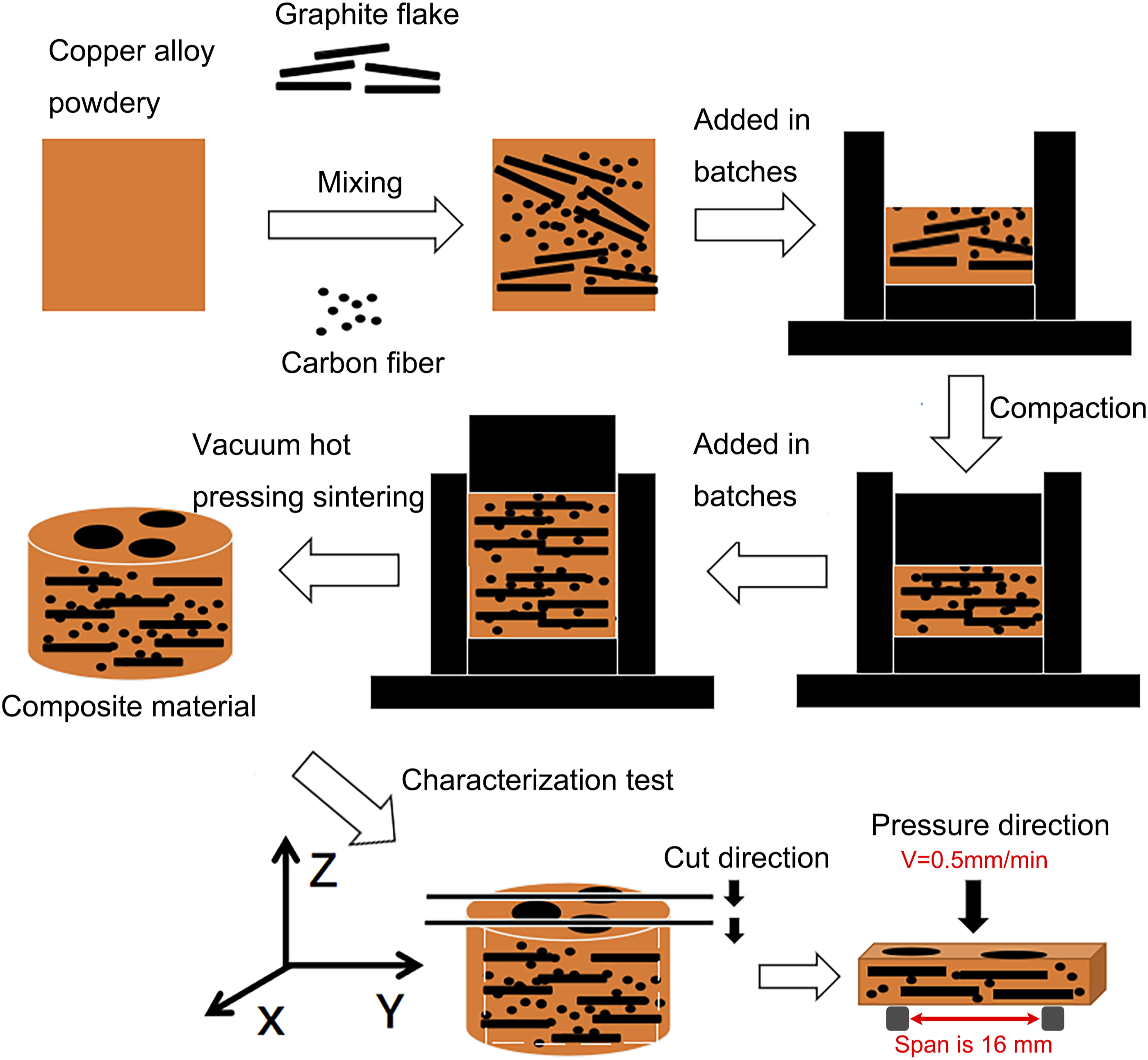
Preparation process
Content of each component of the sample.

Performance testing and microstructure characterization
Field emission scanning electron microscope and EDS energy spectroscopy (SEM and EDS, Phenom Nano field emission scanning electron microscope, Netherlands) were used to study the microscopic morphology, interface structure, and element distribution of composites. X-ray diffractometer (XRD, DVANCEDAVINCI, Germany) was used to study the phase composition of composites. The Archimedes drainage method is used to measure the relative density of composites. The bending strength of the samples is tested by the three-point bending method. The size of the sample to be tested is 5 mm × 4 mm × 20 mm. The test beam speed is 0.5 mm/min and the span is 16 mm, as shown in Figure 2. The thermal diffusivity of the X-Y plane (normal plane of the hot pressing direction) is measured by the in-plane mode (LFA 467, Germany) of NETZSCH thermal conductivity analyzer. The size of the sample to be tested is Φ25.4 mm × 1 mm. The thermal conductivity of the sample is calculated according to the following formula Sample preparation and characterization diagram.
Results
Comparative study of alloying elements Ti and Zr
Comparison of composite morphology
The SEM morphology and XRD diffraction patterns of carbon fiber-flake graphite/copper matrix composites with Ti and Zr alloying elements were observed perpendicular to the pressing direction (Y-Z plane of the sample was observed), as shown in Figure 3. The cross-sectional SEM images of composites with Ti and Zr are shown in Figure 3(a) and (b), where graphite fibers are represented by black dots, graphite flakes by black strips, and copper matrix by grey substances. Most of the graphite flakes are perpendicular to the pressing direction and have an angle of 5°–20° with the X-Y plane due to compression during sample preparation. The even distribution of graphite flakes in the X-Y plane indicates no agglomeration after ultrasonic dispersion. Morphological characteristics of carbon fiber-graphite flakes/copper matrix composites with different alloying elements (a) Cu-Ti2; (b) Cu-Zr2, XRD patterns of carbon fiber/graphite flakes/copper composite with different alloying elements (c) Cu-Ti2; (d) Cu-Zr2.
Comparison of interface phase composition of composites
Figure 3(c) and (d) shows the XRD diffraction pattern of the carbon fiber-graphite flakes/Cu-X2 composites. As shown in the figure, combined with the PDF card, the (002) and (004) crystal planes of graphite flakes and the (111), (200), and (220) crystal planes of copper were detected whether it’s Cu-Ti2 or Cu-Zr2. TiC diffraction peaks at 2θ = 35.95° and 41.72° were detected in Cu-Ti2, and ZrC diffraction peaks at 2θ = 33.01° and 38.29° were detected in Cu-Zr2, which indicated that Ti, Zr, and C reacted in the composites to form TiC and ZrC.
Figure 4 is a SEM image of the surface of the carbon fiber-graphite flakes/Cu-X2 composites. Take graphite flakes as an example. As shown in the figure, a transition layer is formed at the interface between the graphite flakes and the copper matrix. The transition layer contains both carbon and Ti or Zr. Combining XRD (Figure 3), transition layer is a corresponding carbide layer, namely: TiC or ZrC. The carbide layer is well bonded at the interface between the graphite flakes and the copper matrix, without pores, and the thickness of the carbide layer is 0.78 μm and 0.36 μm, respectively. It shows that the carbide layer formed by introducing Ti or Zr improves the interface bonding between the graphite flakes and the copper matrix. Surface scanning image of carbon fiber/graphite flakes/copper composite with different alloying elements (a) Cu-Ti2; (b) Cu-Zr2.
Ti or Zr can be detected not only in the carbide layer but also in the copper matrix. This shows that during the vacuum hot pressing sintering process, most of the alloying elements diffuse to the interface at high temperatures and combine with carbon to form corresponding carbides. A small amount of alloying elements remain in the copper matrix, which they play a solid solution strengthening effect on the matrix, but they will have an impact on the intrinsic thermal conductivity of the copper matrix.
Comparison of thermophysical properties of composites
Properties of carbon fiber-graphite flakes/Cu-X2 composites.
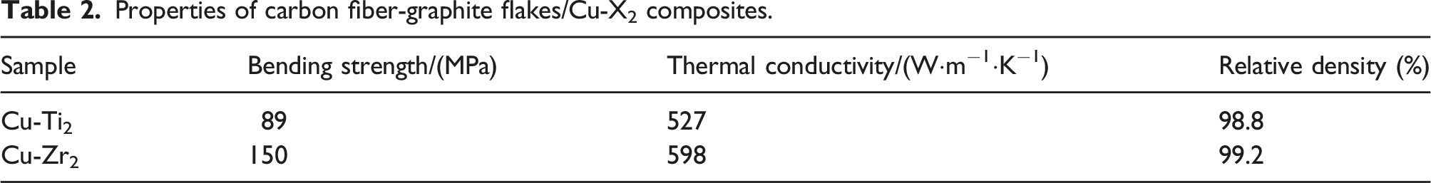
The mechanical properties of alloyed materials are significantly affected by solution strengthening, 32 as lattice distortion after adding alloying elements impedes dislocation slip, thereby improving overall mechanical properties. References33,34 note that the smaller atomic radius and high dispersibility of Ti result in less lattice distortion than Zr when added to the matrix, leading to lower flexural strength in Ti-bearing composites. Zr, on the other hand, forms a replacement solid solution, causing significant lattice distortion and resulting in higher flexural strength in Zr-bearing composites. The aim of this paper is to enhance the strength of the composites without reducing the thermal conductivity as much as possible. Therefore, Zr is more suitable than Ti as an added element in the ternary system of graphite flake-graphite fiber-copper. Therefore, we chose Zr element for further research. In the following study, we will focus on the impact of Zr content on thermophysical properties of composites.
Effect of zirconium content on thermophysical properties of composites
Effect of zirconium content on morphological characteristics of composites
The SEM image of composites prepared with varying zirconium contents is presented in Figure 5, where graphite flake is represented by a long strip, graphite fiber by black spots, and copper matrix by gray parts. Graphite flake and carbon fiber distribution remain uniform across the composites, with no apparent pore formation at any interface. These results indicate that adding Zr elements significantly enhances interface bonding, even at low concentrations, improving the connection between reinforced phases and matrices. Morphology of composites with different Zr content (a) Cu-Zr1; (b) Cu-Zr2; (c) Cu-Zr3.
Effect of zirconium content on interfacial phase composition of composites
Figure 6 is a SEM image of the surface of composites with different Zr content. Taking carbon fiber as an example, as shown in the figure, a carbide layer is formed at the interface between the carbon fiber and the copper matrix. The carbide layer is well bonded and no pores are observed. At 1 wt%Zr, the carbide layer is incomplete; at 2 wt%Zr, Zr was mostly detected near the carbon fibers with a small amount in the matrix, and the carbide layer at the interface tends to be complete; at 3 wt%Zr, a complete carbide layer is formed at the interface and the content of Zr remaining in the matrix increases. In general, as the Zr content increases, the EDS mapping result detects that the Zr content at the interface and the content of Zr remaining in the copper matrix gradually increases and the carbide layer tends to be complete, where the interface thickness increases from 0.21 μm to 1.36 μm. SEM image of composites with different Zr content (a) Cu-Zr1; (b) Cu-Zr2; (c) Cu-Zr3.
Figure 7 is a TEM image of the interface of the Cu-Zr2 composite. Figure 7(a) shows an obvious interface layer whose thickness is basically the same as the thickness of the interface layer in Figure 4(b). The phases on both sides of the interface layer are identified as Cu, Zr, and graphite by selected area electron diffraction analysis. Figure 7(b) is the HRTEM photograph of the interface between the ZrC interface layer and the Cu matrix (area 1). The lattice fringe widths on both sides of the interface are approximately 0.206 nm and 0.271 nm, corresponding to the (111) of Cu and ZrC planes, respectively. There is obvious lattice distortion at the interface, which may be caused by the solid solution between Cu and Zr and the interdiffusion between Cu and ZrC. Figure 7(c) shows the interface structure between ZrC and graphite flakes (area 2). The graphite flakes and ZrC interface layer are well bonded. TEM image of interface of Cu-Zr2 composite (a) Interface morphology; (b) Selective electron diffraction of region 1 in A; (c) Selective electron diffraction of region 2 in A.
Effect of zirconium content on mechanical properties of composite materials
Figure 8(a) compares the flexural strength of carbon fiber-graphite flakes/copper composites with varying Zr contents. As shown in Figure 8(a), the flexural strength initially increases with increasing Zr content, reaching a maximum at 2 wt%, before decreasing. Simple shear hysteresis model (Model 1) can be used to explain the fracture phenomenon of graphite fibers in the composite, as shown in Figure 8(c). In the simple shear hysteresis model, graphite fibers fracture when the applied stress is transferred to the graphite fibers and exceeds a critical point. The basic assumptions of the model are: (1) The thickness of the interface is assumed to be negligibly thin. (2) The interface is perfectly bonded. However, interfaces in composites do not conform to this assumption. The interfacial debonding of the graphite fiber and the matrix should be considered. Interface debonding model (Model 2) takes into account the influence of the interface, as shown in Figure 8(d). In this model, when external loads are transmitted inside the composite material, it will cause relative interface sliding, which may lead to interface debonding when the sliding exceeds a certain degree. In the case of model 1, the crack passes directly through the reinforcing phase, corresponding to the fracture morphology of Figure 8(e), that is, the fractured carbon fiber. In this of model 2, the fibers are observed to be pulled out at the fracture, as is shown in Figure 8(f). In summary, cracks either pass through the reinforced phase (Model 1) or extend along the interface (Model 2), and which fracture mode is actually depends on which fracture mode requires low energy. (a) The flexural strength of composites with different zirconium content; (b) Thermal conductivity and density of composites with different zirconium content; (c) Fracture Model 1; (d) Fracture Model 2; (e) Graphite fiber fracture picture; (f) Graphite fiber pullout pictures.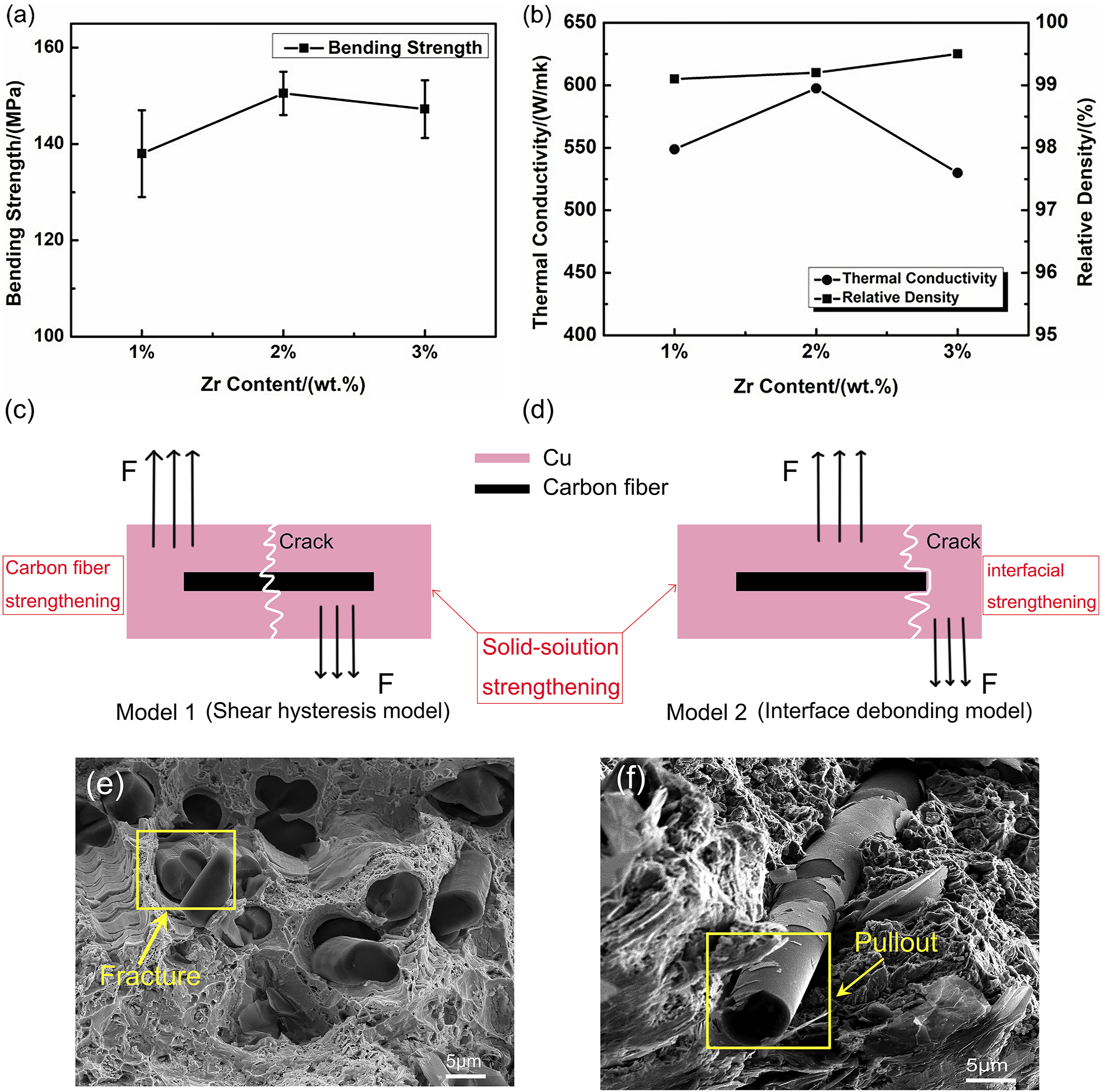
At 1 wt% Zr content, an incomplete carbide layer forms at the interface, resulting in low energy requirements for interface debonding. Zr atoms react preferentially with graphite and therefore produce a weak solid solution strengthening effect in the copper matrix. At this point, model 2 accounts for the majority of the fracture mechanism; the overall flexural strength is 138 Mpa.
At 2 wt% Zr content, a complete and uniform carbide layer forms, increasing interfacial bond strength. At this time, the Zr atom in the Cu-Zr alloy has a low solid solubility in the Cu lattice; the increased Zr atom mostly exists at the boundary between the Cu particles in the form of secondary phase particles which produce a solid solution strengthening effect on the matrix. At this point, model 1 accounted for most of the fracture mechanism, and the overall bending strength of the composite reached a maximum of 150 Mpa.
At 3 wt% Zr content, although the carbide layer at the interface is uniform, model 1 still accounts for most of the fracture mechanism; the mechanical properties of the composite are basically unchanged. However, due to the increase of Zr element, a thick carbide layer is formed at the interface. Excessive thermal resistance will lead to the decrease of thermal conductivity of composites. In addition, excessive brittle carbide phase at the interface would fail first in the composites, and as a result, the bending strength of the composite film decreases. 35 Therefore, when Zr content is 2 wt%, the composite shows good comprehensive performance.
Effect of zirconium content on thermal conductivity of composites
Figure 8(b) is a graph of thermal conductivity and relative density of composites with different Zr content. As shown in the figure, as the Zr content increases, the relative density gradually increases. This is because the carbide formed by the reaction of Zr with graphite flakes and carbon fiber reduces the pores at the interface and improves the interface bonding. The carbide layer at the interface gradually becomes complete with the increase of Zr content, thereby increasing the material compactness.
As the Zr content increases, the thermal conductivity of composites first increases and then decreases. At 2 wt% Zr, the thermal conductivity reaches the maximum value of 598 W·m−1·K−1. As the Zr content continues to increase, the thermal conductivity of the composite begins to decrease. On the one hand, although the carbide layer ZrC improves the interface bonding, its thermal conductivity is lower than that of copper, graphite lakes, and carbon fiber, and it is regarded as a poor thermal conductor. If excessive carbides are formed at the interface, it will adversely affect the heat conduction at the interface of composite. Therefore, although the formation of carbides can improve the interface bonding and reduce the interface thermal resistance caused by the interface pores, it will also introduce new interface thermal resistance due to its own low thermal conductivity. On the other hand, Zr that has not formed carbides at the interface remains in the matrix (see Figure 6), which will reduce the intrinsic thermal conductivity of the matrix.
Thermal simulation of multiphase composites
Digimat software can predict the constitutive behavior of inhomogeneous phases and anisotropic materials. Using the MF module, a fully coupled nonlinear analysis can be realized, and the thermal conductivity of the multiphase composite when the inclusions are uniformly distributed can be calculated by simulation. The MF module is based on the Eshelby inclusion theory and a tool for multiphase nonlinear material constitutive prediction using Mean Field homogenization method. Therefore, this experiment uses Digimat software to simulate the thermal conductivity of composites. The experimental thermal conductivity of composite is measured by Laser flash method.
In this experiment, composites with copper as the matrix and graphite flakes and carbon fibers as the reinforcing phase were constructed, and the thermal conductivity of composites in the in-plane direction was simulated and predicted. Both graphite flakes and carbon fibers are anisotropic reinforcing phases, and their distribution in the matrix affects the thermal conductivity of the material. Therefore, this experiment simplified the model: the graphite flakes are all parallel to the in-plane and the fibers are randomly distributed in two dimensions on the in-plane. The model establishes a randomly distributed three-dimensional structure model by setting the volume fraction of each phase. The graphite flakes and fibers are randomly inserted into the copper matrix when the orientation setting is satisfied, and the thermal conductivity of composite with different alloy elements in all directions can be obtained.
This experiment mainly discusses the thermal conductivity of composites on the in-plane. To make the simulation more in line with the actual situation, the intrinsic thermal conductivity is modified to the effective thermal conductivity. Considering that carbides are formed at the interface in the actual process, the carriers are lost at the interface in the process of transferring energy, that is, there is interface thermal resistance. The thermal resistance R can be regarded as a thermal barrier coating wrapped on the surface of the graphite flakes and fibers, and so it will have a certain impact on the intrinsic thermal conductivity of the graphite flakes and carbon fibers. According to the series method, the relationship among the effective thermal conductivity, intrinsic thermal conductivity, and interface thermal resistance of the reinforcing phase can be obtained, as follows

The interface thermal resistance 
The intrinsic thermal resistance R3 of the carbide layer is calculated according to its formula


Parameters used in theoretical calculation of AMM model.

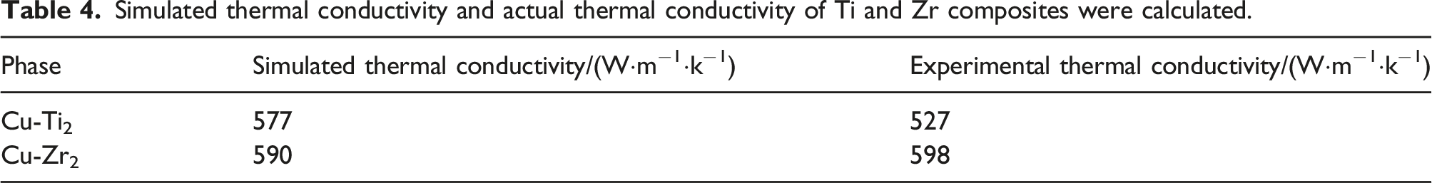
Simulated thermal conductivity and actual thermal conductivity of Ti and Zr composites were calculated.
Conclusion
(1) By adding alloying elements Ti and Zr to the copper matrix, carbon fiber-graphite flakes/copper matrix composites were prepared by vacuum hot pressing sintering technology, and the best alloying element, namely, Zr element, was determined by comparing the phase structure and comprehensive properties of the composites. (2) The content of Zr element plays a decisive role in the formation of interfacial carbides. With the increase of zirconium content, the carbide layer at the interface gradually tends to be complete from incomplete, and the carbide layer is the best when Zr is 2 wt%, that is, the thickness is 0.36 μm. (3) When the carbon fiber is 2 vol% and the Zr content is 2 wt%, the thermophysical properties of the carbon fiber-graphite flake/copper composite reach the best flexural strength of 150.5 MPa and the thermal conductivity of 597.5 W/(m·K), and the composite has better thermophysical properties. (4) The AMM model combined with MF software can effectively predict the thermal conductivity change of multiphase synergistic reinforced copper matrix composites, which can make up for the design shortcomings of multiphase composites.
Footnotes
Acknowledgements
Thanks to Hunan MAG New Material Technology Co. Ltd for providing testing services to this study.
Author Contributions
Conceptualization: Youming Chen and Qian Liu; Methodology: Tongle Liu and Guodong Miao; Formal analysis: Junchen Huang; Resources: Bing Yang; Writing – Original draft preparation: Tongle Liu and Guodong Miao and Junchen Huang; Project administration: Bing Yang; Funding acquisition: Qian Liu and Youming Chen.
Declaration of conflicting interests
The author(s) declared no potential conflicts of interest with respect to the research, authorship, and/or publication of this article.
Funding
The author(s) disclosed receipt of the following financial support for the research, authorship, and/or publication of this article: This work was supported by the Fund of Hunan Provincial Education Department (21B0468).