
Abstract
In order to enhance the fitness of the product and in order to improve productivity in turning operations, greater amount of challenges have been faced. In this paper, we have made a comparative analysis of HSS and carbide coated HSS drills while machining with H13 steel plates. For the drilling operation, process parameters were analysed using the Taguchi design of experiments. The response performance characteristics of surface roughness of H13 die steel plates for the drilling settings, cutting speed (rpm), and feed rate (mm/min) is optimized. The design of the experiment was conducted using the Taguchi technique for the L18 orthogonal array, and an analysis of variance was observed. The effect of drilling settings on the quality of drilled holes is examined; variation in surface roughness for various levels of speed and feed and the different combinations of these levels will form an L18 orthogonal array design of experiment by Taguchi analysis. A total of 36 cutting tests were performed with two different drill bits; here three different cutting speeds of 300, 600, and 900 rpm were taken with a feed rate of 0.02, 0.04, and 0.06 mm/rev combinations. The response of SN ratio for surface roughness of HSS and carbide tool has been found out for different levels of speed and feed. From this Taguchi analysis, it is identified that the optimal parameter. As a result, the factors are analysed, and optimized parameters have been concluded for H13 material using HSS, and carbide tools were examined both statistically and experimentally. The carbide coated drill bit gives 60% better surface roughness value based on experimental data obtained. The surface roughness value based on experimentation for HSS tool was found to be 34.16% and carbide coated drill bit was 23.40%.
Introduction
Shear deformation of the work material is the most common cutting action in machining, and it leads to the generation of numerous types of chips. While removal of chips, a new surface is revealed, which is referred to as the machined surface. The response performance characteristic of the surface roughness of H13 die steel plates is used to improve the drilling parameters, which include two factors such as cutting speed (rpm) and feed rate (mm/rev) An attempt has been made to optimize the drilling parameters using Taguchi's technique, which is based on the robust design. 1 Experiments are carried out on machining the various %volume of Si3N4 in epoxy Si3N4 composite materials, using the HSS tool for various cutting conditions and the diameter of the drill bit.2,36,37 The results revealed that the combination of factors and their levels A2B3C2D1, that is, the machining is done in the presence of cutting fluid at a speed of 500 rpm. With a feed of 0.04 mm/s and hole-depth of 25 mm yielded the optimum, that is, minimum surface roughness. 3 The optimization of the machining process with numerous performance criteria for raising the standard of the drilled holes is made simpler by the combination of Grey Relational Analysis and Taguchi analysis. 4 The combination of a 25-degree helix angle, a feed rate of 12 mm per minute, and a spindle speed of 800 r/min results in cutting settings that are optimal for surface roughness. The combination of a 25-degree helix angle, a feed rate of 10 mm/min, and a spindle speed of 600 r/min results in cutting conditions that accelerate vibration to the greatest extent.5,7,8 The most important component affecting the surface roughness was the cutting tool, which contributed 39.14%, while the most important factor determining the thrust force was the feed rate, which contributed 82.77%. 6 The most important parameters that determine surface roughness are feed rate and spindle speed; however, using abrasive slurry has resulted in an overall improvement of about 11% in surface roughness. 9
The most important parameters that influence surface roughness are feed rate and spindle speed. However, the abrasive slurry has been shown to improve surface roughness overall by about 11%.10,11 Delamination during post-assembly can be decreased by reducing die and mould thickness. The copper thickness has no effect on the energy release rate.12,13 Uncoated drills caused less delaminating than TiN and TiAlN-coated HSS drills, and optimum cutting parameters were determined as the high cutting speed, low feed rate, and drill point angle combination.14,15 In this paper, the effects of the two input process parameters such as spindle speed, feed rate on surface roughness using carbide coated drill and HSS drill bit to determine optimum machining conditions on H13 die steel. The experiments were carried out in CNC Vertical Machining Centre. For this purpose, the experiments were done according to the Taguchi L9 orthogonal array, and comparative analysis of L18 orthogonal array designed and optimal parameters found out. The effect levels on the surface roughness of the control factors with analysis of variance (ANOVA) performed using the experimental results were determined. Experiments were carried out via the L18 orthogonal array. Control factors for optimum surface roughness (Ra) values were determined by using the Taguchi method. Two different grinding wheels, three different cryogenic samples, and three different depths of cuts were selected as control factors. The optimum values for the surface roughness were found to be a point angle of 118°.16,17 The surface roughness parameters were investigated using two drill bits with three different feed and speed, and the results were examined both experimentally and statistically. 18
Cutting force (Fc) and study of the machined surface in turning of AA 6061 alloy with uncoated and PVD-TiB2 coated cutting inserts have been the main topics of research. On a CNC turning with dry cutting, turning experiments have been undertaken. The outcomes showed that an uncoated insert produced the greatest results in terms of Fc and Ra. Moreover, the feed rate has the greatest impact on Ra and Fc. 19 The most important independent factors that affected delamination on GFRPs were feed rate and tool material. Moreover, less delamination thrust force is produced by ultrasonic and vibration-assisted drilling procedures than by conventional drilling. Kavad B V et al. (2014) 20 discovered that cooling techniques had an impact on the temperature of the drill flank and the risk of GFRP damage. They used RSM to explore the various parameters and found that increasing the feed rate while maintaining the speed raises the drill temperature while maintaining the damage factor. However, increasing the feed rate while maintaining a fixed spindle speed raises the damage factor and drill temperature.21,32 The specimen with uncoated twist drills produces the greatest quality products with less delamination and tool wear, according to research using titanium aluminium nitride coated twist drills. 22 Findings indicate that materials thickness, not fibre orientation or feed rate, has the greatest influence on peel-up delamination. Therefore, feed rate has the greatest impact on push-down delamination. Further research revealed that push-down laminates had a more significant impact than peel-up laminates.23,35
Drilling while accounting for cutting forces was used to evaluate the delamination on carbon fibre reinforced composites. According to the authors' analysis of three different drilling techniques – conventional, orbital, and circular drilling – delamination values at higher feed rates during the circular drilling process are relatively very low compared to those at lowest feed rates for orbital and conventional drilling. By maximising the tool geometry parameters, polymer composites with carbon reinforcements were created and a study of drilling operation delamination and cutting forces was conducted. They have determined that reducing the feed rate and nominal feed of cut when drilling, particularly with reamer and brad drill bits, reduces delamination. 24 Less damage occurs during delamination when drilling CFRP with a helical drill bit operating at its maximum cutting speed. Also, authors claimed that the Reamer drill bit is best for drilling CFRP composites with the least amount of delamination based on their experimental findings. Feito et al., 25 Mohan et al., 38 and Sunny et al., 39 worked on drilling in GFRP while experimenting with different machining parameters to determine how they affected torque, push out, peel ups, and other factors. Because the epoxy polymer matrix has a low thermal conductivity, they have found that the pre-increment of wear causes an increase in surface roughness because heat is produced. Artificial neural networks and multivariable regression models are used to assess the bearing capacity of drilled holes. 26 Studying the impact of the silicon nitride content (Si3N4) on epoxy composite drilling characteristics led researchers to identify Si3N4 as the main cause of circularity, surface roughness, and cylindricity. 27 Drilling was done on polypropylene GFRP composites using three different types of tools, and the results showed that increasing feed rate results in an increase in thrust force, but that the value of thrust force is reduced at higher spindle speed and that using solid carbide and tripped carbide tools results in less delamination damage developing. 28 The smoothness of the drilled surface, as seen by SEM photographs, was another imported observation. 29 The drilling of GFRP composites was evaluated by optimising the drill diameter and other factors, and it was shown that variations in feed rate result in good surface finish and reduced thrust force. Moreover, it is concluded that changing the spindle speed had little to no impact on composites.30,31 Several failures have developed while drilling composite materials, including delamination, swelling, fibre pullout, edge chipping, and surface roughness.33,34
The experiments were carried out with a normal HSS tool, and carbide coated tool with various cutting speeds and feed rates over H13 die steel material. The quality of drill bit has been assessed with respect to H13 die steel. For various degrees of speed and feed, the response of the SN ratio for surface roughness of HSS and carbide tools has been discovered. The ideal parameter is determined by this Taguchi analysis. As a consequence, the variables are reviewed, optimal parameters for H13 material utilising HSS have been determined, and carbide tools have been statistically and experimentally investigated. For multi objective optimization process, Grey Relational Analysis was performed using the following parameters such as spindle speed, feed rate, and drill bit were considered to find the optimum result for MRR and surface roughness.
Materials and methods
H13 die steel is generally a hot work steel which is used for both hot and cold work tooling, and it’s basically chromium–molybdenum hot work steel. Repeated heating or repeated cooling cycles in tooling applications while hot work causes thermal fatigue cracking. The hot hardness (hot strength) of H13 is resistant to this. The properties such as excellent heat resistance, wear resistance, high hardness, and ability to withstand thermal fatigue made H13 die steel to find its applications in dies, punches, shaft, axles, and mould components due to its strength to weight ratio. Due to its outstanding combination of extraordinary toughness as well as resistance against thermal fatigue cracking H13 is primarily used for more hot work tooling applications than any other tool steel. They have superior hardenability (due to wide section thickness hardening) and wear resistance than popular alloy steels like 4140.
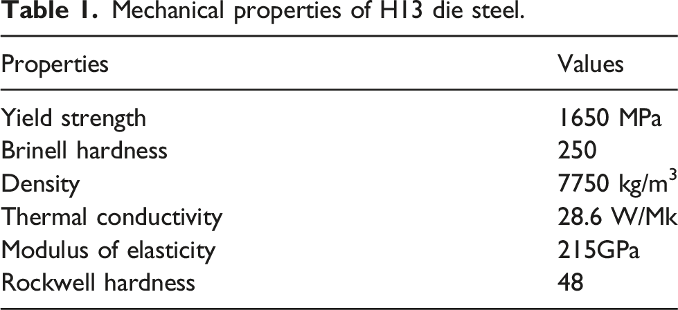
Mechanical properties of H13 die steel.
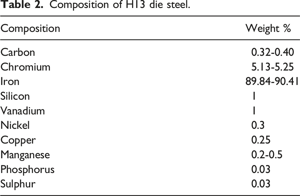
Composition of H13 die steel.
H13 die steel is generally hot work steel which is used for both hot and cold work tooling, and it’s basically chromium–molybdenum hot work steel. The enhanced thermal wear and cracking produced by repeated heating or cooling processes in a hot work tool and die applications are resistant to H13's recent hardness (hot strength). The incredible mixture of high toughness and thermal fatigue resistance prevents breaking (also called heat cracking). H13 is a tool steel that exceeds other tool steels when it comes to additional hot work in tooling applications. Because of its high hardness and excellent heat treatment durability, the H13 die steel has also been employed in a wide range of cold work tooling applications. Here, H13 has better hardenability and wear resistance than typical alloy steels like H11 and H12.
Machine details
Figure 1 shows the drilling operations performed on an AMS MCV-450 Vertical Milling Centre. The CNC vertical machining centre used here has a multiple spindle speed range of up to 6000 r/min. Table 3 explains the machine configuration. The process parameters that were chosen for testing includes cutting speed in rpm and feed rate in mm/rev. CNC vertical machining centre. Configurations of VMC.

HSS (high-speed steel) is a tool steel that is more heat resistant and harder than high-carbon steel. They can drill metal, hardwood, and most other materials quicker than carbon steel bits, and they have almost completely replaced carbon steel bits.
The selected straight shank type drill bit is made of HSS with total length of 200 mm, shank diameter 10mm, flute length of 145 mm with tip angle 118o, and with diameter of 10 mm. In high-volume applications, carbide drill bits are extremely effective. Carbide enables extremely fast cutting speeds, long tool life, and the flexibility to work with an extensive range of materials. The cutting edge of the drill bit keeps its efficacy well past that of cobalt and HSS due to carbide's hardness. The selected drill bit is a shank type made of carbide coated of total length 200 mm, shank diameter 10 mm, flute length 145 mm, drill bit diameter 10 mm, and with tip angle of 118o
Design of experiment
L9 orthogonal array.

Results and discussion
According to the experiment design, the experiment was carried out on H13 die steel, shown in Figure 2, with different process parameters. The H13 die steel used for experimentation is 80 mm x 80 mm x 6 mm in size. HSS drills and carbide coated drills are used in the drilling process. The SN ratio is used to examine the results of drilling process parameters. Surface roughness testers are used to find the Surface roughness value, and the results are reported in Table 4. The experimentation has been conducted considering two major contributing parameters as per literature, namely cutting speed and feed rate. The cutting speeds opted for investigation are 300, 600, and 900 r/min. Similarly, the feed rates opted for investigation are 0.02, 0.04, and 0.06 mm/rev. Mitutoyo Surface Roughness Tester SJ-410 was used for measuring surface roughness. H13 steel drilled specimen (HSS Drill bit).
Analysis for HSS drill bit
SN ratio for surface roughness in HSS drills.

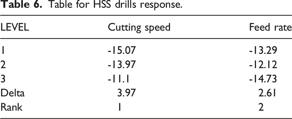
Table for HSS drills response.
Surface roughness in HSS drill ANOVA table.

Figure 3 shows the SN ratio of H13 die steel plates while performing drilling operations. It also shows that the spindle speed at the first level and feed rate at the third level yield lesser surface roughness. So, for producing high-precision, high-toughness dies, the H13 steel plates are ideal. According to this Taguchi study, the best parameter for achieving a smooth surface is 900 r/min at 0.04 mm/rev. Figure 4 shows the change in surface roughness for various speeds and feed rates, as well as the same optimal value for the SN ratio. The validation experiment was conducted, and the results are presented in Table 8. Main effect plot for SN ratios of surface roughness in HSS drill. Contour plot of surface roughness versus speed, feed in HSS drill. Validation experiment and its results.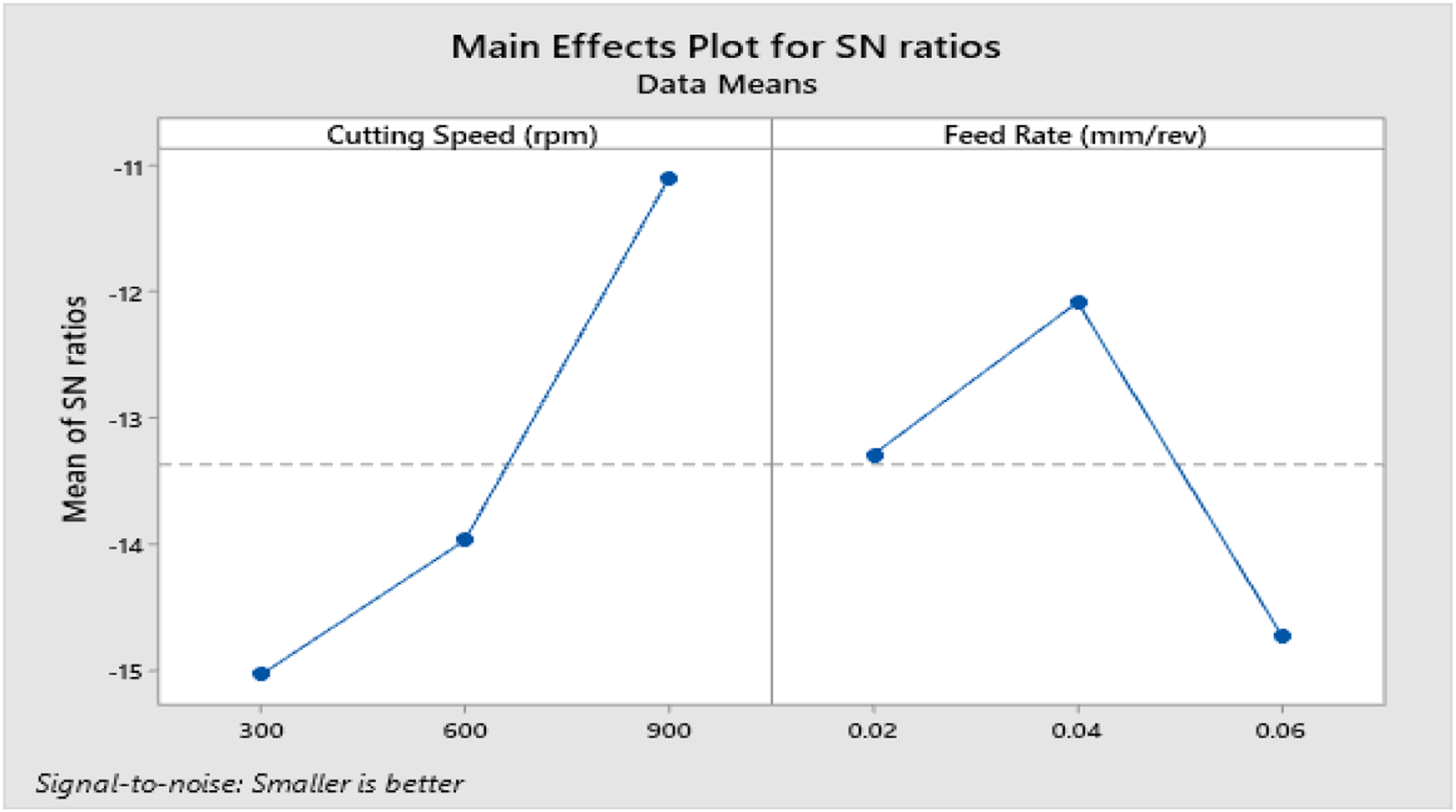


Analysis for carbide coated drill
SN ratio for surface roughness in carbide coated Drill.


H13 steel drilled specimen (carbide coated drill bit).
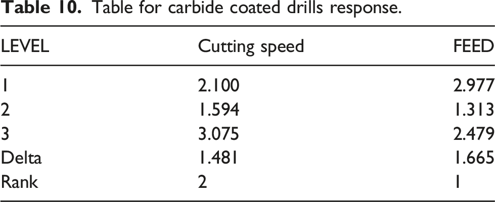
Table for carbide coated drills response.
Surface roughness in carbide coated drill ANOVA table.

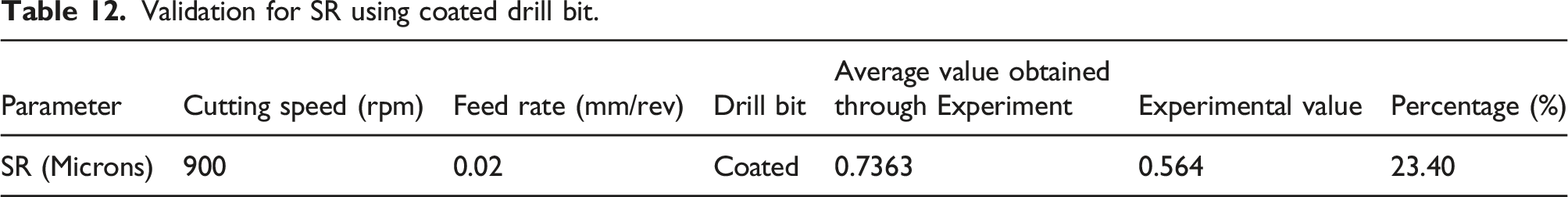
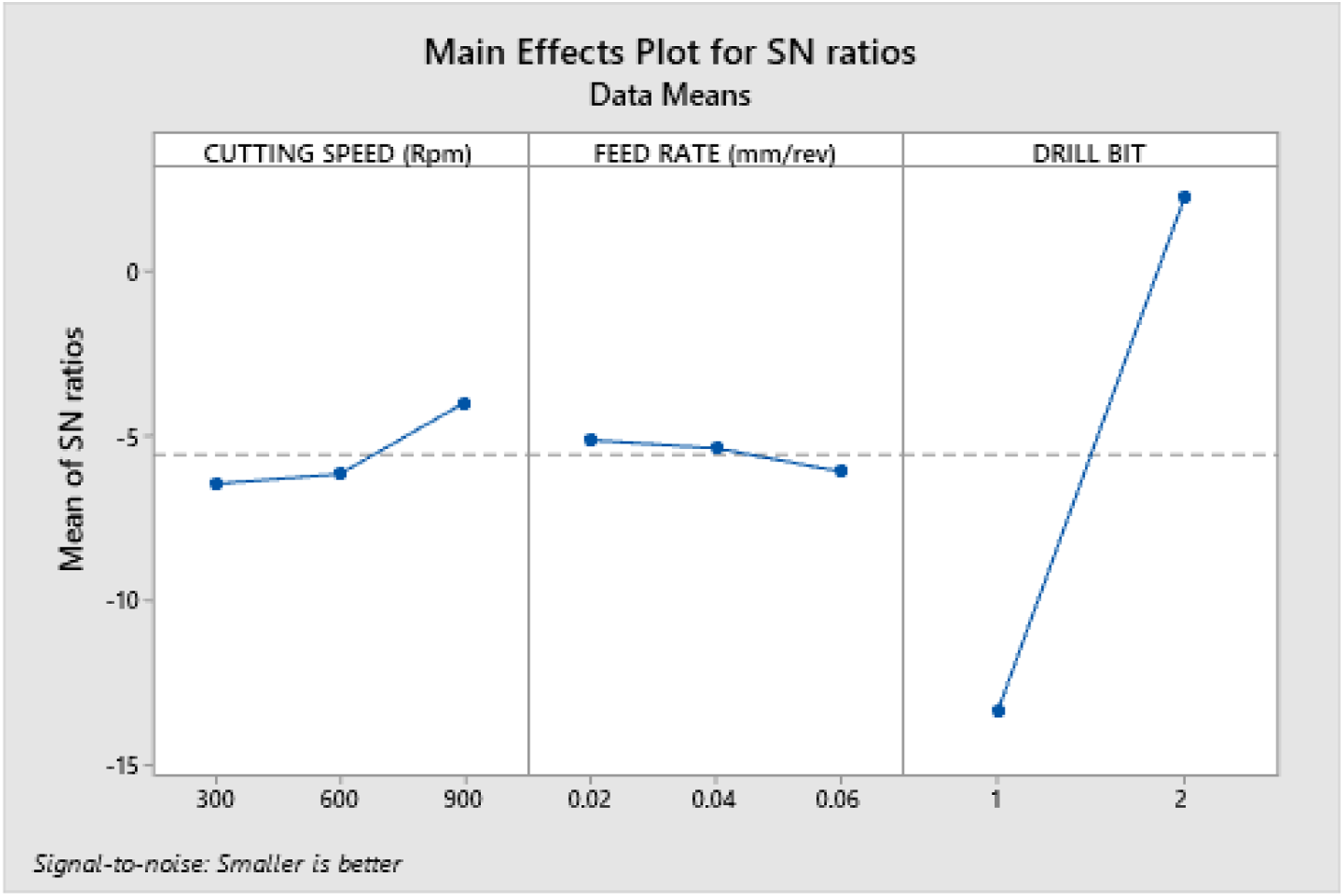
Figure 6 shows the SN Ratio of H13 die steel plates while performing the drilling operation. It also shows that the second level of spindle speed and the second level of feed rate produce lesser surface roughness. The H13 steel plates are ideal for producing high-precision, high-toughness dies. According to this Taguchi study, the best parameter for achieving a smooth surface is 900 r/min at 0.02 mm/rev. Figure 7 shows the variance in surface roughness for various speeds and feed rates, as well as the same optimal value for the SN ratio.45–47 The validation experiment was conducted, and the results are presented in Table 12. We can see from the plot for SN ratio in Figure 8 that the analysis is based on the assumption that a larger value equals higher surface roughness. SN ratio Main Effect Plot of surface roughness in carbide coated drill. Surface roughness Vs speed, feed in L18 analysis for contour plot. Validation for SR using coated drill bit. Contour plot of surface roughness versus speed, feed in carbide coated drill.

Comparative Analysis of L18 orthogonal array
Experimental reading of comparative analysis.

Surface roughness S/N Ratio of comparative analysis.

The average SR decreases to 2.915 microns from 3.275 microns (12.35%) with an increase in cutting speed from 300 r/min to 600 r/min. With a further increase in cutting speed from 900 r/min form 600 r/min, the SR has again decreased from 3.275 microns to 2.205 microns which is 32.20%. Similarly, with an increase in feed rate to 0.04 mm/rev from 0.02 mm/rev, the SR reduces from 2.756 microns to 2.5 microns. But, with a further increase in feed rate from 0.04 mm/rev to 0.06 mm/rev, the SR increases by 20.34% from 2.5 microns to 3.138 microns. The SR decreases by 514.49% when the coated drill bit is used when compared to the HSS drill bit. We can see from the plot for the SN ratio in Figure 9 that the analysis is based on the assumption that a larger value equals higher surface roughness. According to the Taguchi study, the best parameter for achieving a smooth surface is 900 r/min at 0.02 mm/rev when using carbide coated drill bit. SN ratios main effect plot of surface roughness in L18 Analysis.
Figure 9 shows the variance in surface roughness for various speeds and feed rates, as well as the same optimal value for the SN ratio.
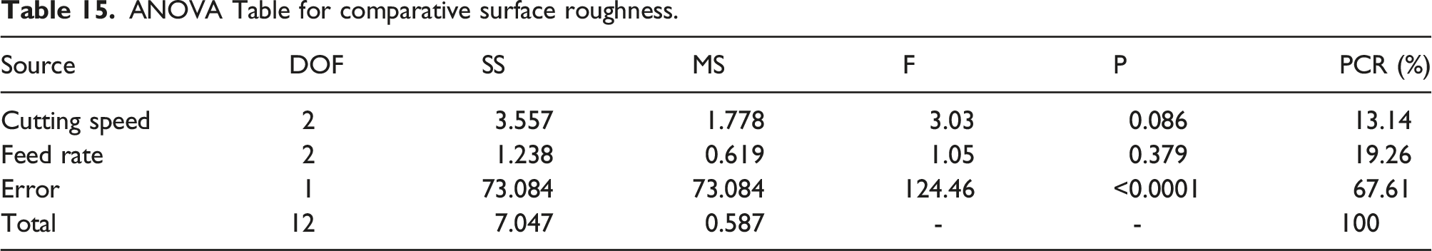
ANOVA Table for comparative surface roughness.
The MRR increases by 46.34% from 0.058 to 0.109 g/sec when the cutting speed increase from 300 r/min to 600 r/min. With a further increase in cutting speed to 900 r/min, the MRR has increased by 25.37% from 0.109 to 0.146 g/sec. On the other hand, the increase in feed rate has also increased the MRR. An increase of 47.08% is seen with the increase of MRR from 0.058 to 0.111 g/sec when the feed rate increases from 0.02 mm/rev to 0.04 mm/rev. When the feed rate is further increased from 0.04 mm/rev to 0.06 mm/rev, the MRR again increases from 0.111 to 0.1445 g/sec, which is 23.07% higher than the MRR for 0.02 mm/rev.
The analysis is based on the assumption that a bigger value will result in a higher MRR, as shown in the Figure 10 plot for the SN ratio. According to this Taguchi study, the best parameter for providing a smooth surface with a higher MRR for a carbide coated drill bit is 900 r/min at 0.02 mm/rev. The contour plot in Figure 11 demonstrates the fluctuation in MRR for various levels of speed and feed, with the same optimal value as the SN ratio. Plot for SN ratio of MRR. MRR vs. speed and feed for contour plot.

ANOVA table for MRR.

Validation experiment and its results.

GREY relational analysis in drilling
MRR Reading in HSS Drill.

GRA able MRR analysis.

From Figure 12, it is identified that the different levels of speed and feed are analysed and plotted in the graph. The most significant factor is the drill bit with 66.21% of the contribution, and p value is <0.0001. Similarly, the second most significant factor is cutting speed with 20.09%, and the p value is <0.0001. The least significant factor is feed rate which has a p value of 0.002 with an 8.91% contribution. Table 20 shows the ANOVA analysis for GRG. Plot for optimal parameters in GRG analysis. ANOVA for GRG.

Conclusions
The speed and feed are variable numerical parameters in the machine, and the drill bit is an arbitrary parameter, according to the analysis of drilling operations in H13 material. The MINITAB Statistical Program was used to conduct the statistical analysis, and the findings were obtained using the Taguchi and ANOVA procedures. • With a 10mm diameter HSS drill bit in L9 orthogonal, the ideal setting for achieving a flat surface is 900 rpm and 0.02 mm/rev. The validation experiment was conducted, and the SR obtained was 51.90% lesser than the mean value of the SR during experimentation. Cutting speed was found have more significance over SR with 56. 23%, and the second parameter of significance is feed rate, with a 24.46% contribution. Spindle speed was found have more significance over SR with 56. 23%, and the second parameter of significance is feed rate, with a 24.46% contribution. • Similarly, the optimal settings for achieving a smooth surface when using a 10 mm diameter of carbide coated drill in L9 are 900 rpm and 0.02 mm/rev. The validation experiment was conducted, and the SR obtained was 38% lesser than the mean value of the SR during experimentation. The feed rate contributes 19.26% in achieving the desired SR, followed by cutting speed with 13.14%. The feed rate contributes 19.26% in achieving the desired SR, followed by cutting speed with 13.14%. • In L18 orthogonal analysis, the ideal parameters for generating a smooth surface with a carbide coated drill bit of 10mm diameter are 900 rpm and 0.02 mm/rev. The feed rate is identified to have more contribution towards obtaining the SR, followed by cutting speed. The feed rate contributes 19.26%, and the cutting speed contributes 13.14%. The P value for cutting speed and feed rate is 0.086 and 0.379, respectively. • According to this Taguchi study, the best parameter for providing a smooth surface with a higher MRR for a carbide coated drill bit is 900 rpm at 0.02 mm/rev. The cutting speed is identified to have more contribution towards obtaining the MRR, followed by the feed rate. The cutting speed contributes 49%, and the feed rate contributes 46.34%. The P value for both cutting speeds. • In the case of multi-objective optimization carried out using GRA, the optimal settings optimized parameter for higher MRR and reduced SR is 900 rpm of cutting speed, 0.06 mm/rev of feed rate, and coated drill bit. The most significant factor is the drill bit, with 66.21% of the contribution. Similarly, the second most significant factor is cutting speed, with 20.09%. The least significant factor is feed rate, with an 8.91% contribution.
The spindle speed contributes 49%, and the feed rate contributes 46.34%. The p value for both spindle speeds.
• In the case of multi-objective optimization carried out using GRA, the optimal settings optimized parameter for higher MRR and reduced SR is 900 rpm of spindle speed, 0.06 mm/rev of feed rate, and coated drill bit. The most significant factor is the drill bit, with 66.21% of the contribution. Similarly, the second most significant factor is spindle speed, with 20.09%. The least significant factor is feed rate, with an 8.91% contribution.
Footnotes
Acknowledgments
The researchers would like to acknowledge Deanship of Scientific Research, Taif University for funding this work.
Declaration of conflicting interests
The author(s) declared no potential conflicts of interest with respect to the research, authorship, and/or publication of this article.
Funding
The author(s) disclosed receipt of the following financial support for the research, authorship, and/or publication of this article: The researchers would like to acknowledge Deanship of Scientific Research, Taif University for funding this work.