
Abstract
In this work, mechanical performance on sandwich composites consisting of syntactic foam filled with hollow glass microsphere in an epoxy resin matrix as the core material and hybrid kenaf/glass fibers face-sheet based composites panel is studied. The main purpose of this work is to design a suitable lightweight composite panel material for structural application. Four different sequences of face-sheet reinforcement (e.g., kenaf-kenaf; glass-glass; glass-kenaf, and kenaf-glass) were adopted. In this study, the mechanical properties and failure modes are carefully investigated. The sandwich composites were characterized by compressive, tensile, and flexural properties. The results showed that compressive strength was highest at the “kenaf-glass” face-sheets, tensile strength was highest at “glass-glass” face-sheets, and flexural at “glass-glass” face-sheets with 52.1%, 67.6%, and 74.4% increase to “kenaf-kenaf” face-sheets, respectively. The tensile strength and modulus values with the specific strengths and modulus values showed that the mechanical properties of the sandwich composites can be influenced by hybridizing the face-sheet laminates of the composite. This shows that kenaf fiber has limited strength when used as reinforcement alone but gave an excellent performance when combined with glass fiber.
Introduction
The application of lightweight structures made of hybrid sandwich composite panels is widely accepted in aerospace, marine, and automobile industries due to good mechanical performance and thermal stability properties. Sandwich panels are known for their reliability and applicability in different sectors and industries such as automobile, marine, wind turbine, aerospace, railway system, and structural application. The concepts of the sandwich structure have been in use for over two decades with several processing methods. Many core materials have been used in the past by researchers for the sandwich panel. Still, syntactic foam core is mainly preferred because of its high bending rigidity, good thermal insulation, better acoustic damping characteristics, and lighter weight.1,2 Using syntactic foam as core material enhances weight-saving in marine applications and improves the sandwich structure’s performance.1,3–8 The bending stiffness of the composite material can also be improved by using syntactic foam as a core in the sandwich composite.
The face-sheets of the sandwich composites are known to be the carrier of different loads, viz, compressive flexural and strength. At the same time, the thicker core provides the reinforcement and ensures adequate shear stiffness with low specific weight to absorb applied shear forces. When the combined weight of the face-sheet is almost that of the core, an efficient sandwich composite structure is produced. The relationship between the face-sheets/core/face-sheets bonding defines the characteristics of the sandwich composites. In designing the laminated composite structure, many design variables are involved. Several face-sheets have been used as skin ranging from natural to glass fibers such as sisal, jute, banana, kenaf, flax, glass, paper, and carbon fabrics.5,9–14
In literature, the most commonly used core materials in sandwich panels are aluminum honeycomb, 11 polyvinyl chloride (PVC), 15 polystyrene, polyurethane, wood, polyethylene terephthalate (PET), 9 and syntactic foam, which in recent time has become the most used of all the cores.14,16 Studies on syntactic foam sandwich composites are available in the literature, wherein most research focuses on the mechanical characterization of foams and their sandwiches. Islam and Kim 14 investigated the tensile and flexural response of sandwich composites prepared with paper skin and syntactic foam core. They observed that the skin paper contributed to a 40% increase in the estimated flexural strength over syntactic foams depending on the starch content in the adhesive between the syntactic foams core and paper skin. Moreover, Waddar et al. 17 studied the buckling and free vibration response of sisal fabric/epoxy skin and syntactic foam core via experimentally and numerical observation. The weight-saving potential of untreated and treated cenosphere/epoxy syntactic foams was 15.81% and 14.61%, respectively, compared to neat samples. The sandwich beams were also discovered to show global buckling mode shapes without skin delamination or wrinkling. Also, syntactic foam emphasized the current categories of various polymer materials, filler materials, micro-scale, and nanoscale reinforcement, their processing method, and their effects on the properties of syntactic foams with deformation and fracture mechanics. Amol Patil et al. 18 observed an increase of 111% in impact strength and 58% in flexural modulus of hybrid syntactic foam compared to plane hollow glass microballoons syntactic foam. The effect of microstructure and wall thickness of HGM on syntactic foam core has been previously studied by the author, where the wall thickness of HGM improved the flexural strength and specific flexural strength by 71% and 68%, respectively. 19 Moreover, the syntactic foam has affected the mechanical behavior of composite materials in several ways, such as increasing the damping capacity of 6061Al/fly ash foam than the matrix alloy, 20 increasing the compressive strength of solid glass microsphere by 8.6% more than the cured epoxy, 21 facilitated an overall decrease in glass fiber reinforced plastic sandwich density. 22 It enhanced the sandwich composite’s structural performance, energy absorption ability, peak load, and stiffness. 23
Composite sandwich materials are suitable carriers of bending stress and impact response when subjected to the ballistic test. This was investigated by Ahmadi and Liaghat, 2 who studied the analytical and experimental impact of high-velocity loading on the foam core sandwich panel using woven fiberglass as the skin. The foam core failure was discovered to be due to crushing and delamination of the skin, accounting for about 58–80% of the total energy absorbed. Garay et al. 9 also studied the effect of different cores on the mechanical properties of sandwich panels. Two cores (polyvinyl chloride “PVC” and polyethylene terephthalate “PET”) were used with glass fiber (mats or cloths) as the skin. It was discovered that the strength of the PVC core in all the tests was flatwise tensile, flatwise compression, and shear more than the PET core, but the PET core was a better replacement for the PVC core, depending on the type of loading. Ashraf et al. 11 studied the face-sheet’s effect on the sandwich composites’ compression properties. He concluded that the face-sheet has no significant effect on the compression properties. Still, the thickness of the face-sheet has a noticeable effect on the compression properties of the sandwich composite. Also, in the report by Karthikeyan et al. 5 variations of the volume fraction of fiberglass were used to improve the flexural modulus of the syntactic foam core. These core material properties are set based on the cell size and wall thickness. 11
Moreover, the chopped strand fiberglass improved the reinforced syntactic foam’s bending modulus, making it a better choice for a core material in sandwich composites for structural applications. 24 Carbon fabrics as face-sheets also had a better reinforcing effect on the sandwich composites with syntactic foam as the metal matrix core.10,25 Glass and kenaf fiber are not so commonly used as hybrid face-sheet in sandwich composite but were adopted recently for the preparation of a sandwich panel with honeycomb as the core. The thickening effect of the hybrid fibers improved the compressive properties of the sandwich composites. 11 Also, Karthikeyan et al. 5 emphasize the importance of fiber reinforcement for better performance of syntactic foam used as the core in sandwich composites. In the study made by Sharba et al. 26 the investigation was carried out on the hybridization of varying different kenaf fiber as core and fixed six layers of glass fiber as face-sheet. The result showed that the tensile strength reduces as the kenaf core changes, while there was no significant difference in the compressive strength. Also, the bending stiffness of the sandwich composite can be improved by using a honeycomb as the core. Kumar et al. 4 studied various core materials such as nomax honeycomb, kraft honeycomb, and syntactic foam and the combination of nomax and kraft with syntactic foam as core with E-glass face-sheet. The finding showed that combining the core materials gives better compressive properties than individual core and that syntactic foam exhibit shear crack and debris formation. Hybridizing core materials on face-sheet has been studied but the effect of hybridizing different face-sheet by interchanging their sequences on syntactic foam core composite is not yet studied.
Therefore, this study presents a novel sandwich composite material fabricated by hybridizing face-sheets in a different layering pattern to improve its mechanical properties for structural applications. Syntactic foam composite (SFC) was used as a core, kenaf, and glass fibers as face-sheets. Syntactic foam core is utilized based on its advantage of low density and weight-saving compared to foams like PVC. The validity of their mechanical results in terms of compressive, tensile, flexural, and density calculation can be applied to structural and aerospace applications. The notations for the four different hybrid compositions are kenaf-SFC-kenaf (KK); glass-SFC-glass (GG); glass/kenaf-SFC-kenaf/glass (GK); and kenaf/glass-SFC-glass/kenaf (KG). Scanning electron microscopy (SEM) analyses were performed on the fractured surfaces of the sandwich composites.
Materials and method (processing)
Constituent materials used
Densities of constituent materials for the fabrication of sandwich composites.
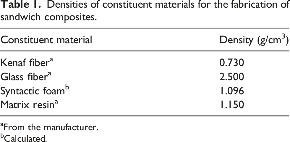
From the manufacturer.
Calculated.
Fabrication of hybrid composite
Suspension of epoxy/HGM
The syntactic foam core with a density of 1.096 g/cm3 was fabricated by mixing HGM and epoxy resin using the degassing method. Detailed processing techniques can be obtained from our earlier work. 27 The thickness of the syntactic foam core used was 20 mm.
Hybrid sandwich fabrication
Figure 1 shows the schematic demonstration of composite sandwich fabrication. It was processed by placing the syntactic foam core in between the upper and lower face-sheets as required at each hybrid composition of the sandwich composites. Hand lay-up was used to bond the face-sheets to the core material before vacuum bagging. 12 plies of woven glass fiber “6 mm” (6 uppers (3 mm) and 6 lower (3 mm) layers) were used for GG, and 4 plies (two upper (3 mm) and two lower (3 mm)) of kenaf fiber mat were used for KK, 6 plies of glass fiber (3 mm) + 2 plies of kenaf fibers (3 mm) were used interchangeably for both GK and KG (3 plies glass/1 ply kenaf as upper and lower face-sheet) respectively, (see Figure 1). The dimension of the slab made for each sample was 320 × 195 × 26 mm3. The angle for layering the face-sheet was 0°/90° for all the sandwich composites. A slight variation of ± 0.1 mm was observed in face-sheets thickness which can be attributed to the undulation of the woven fabric.
17
Schematic diagram of the four sequences of sandwich composites: (KK)-kenaf-SF-kenaf; (GG)-glass-SF-glass; (GK)-glass/kenaf-SF-kenaf/glass; and (KG)-kenaf/glass-SF-glass/kenaf.
The densities of all the constituent materials (Table 1) were considered when calculating the sandwich composite density. The sandwich foam composites were then formed by vacuum bagging. In this method, the sandwich composite was kept under a hot hydraulic press for 24 h to remove excess resin, proper bonding and force out any entrapped air (void) during the hand lay-up process. It was then post-cured in an oven at 70°C for 4 h. Compression, tensile, and flexure test samples were cut from the cured slabs with specifications according to respective ASTM standards using computerized numeric control (CNC) machine and tested accordingly. Three samples were tested for each sandwich composite’s sequences.
Scanning electron microscopy
Fractured surfaces of the sandwich composite were examined under scanning electron microscopy (SEM). The gold coating of each sample was examined under the Zeiss EVO 1 HD 15, Oxford instrument machine operating 20 kV under controlled atmospheric conditions.
Mechanical testing
The compression, tensile, and flexural tests were conducted following ASTM C364-94 (edgewise), 28 ASTM C297, 29 and ASTM C393-94 30 respectively using an MTS machine with a load speed of 0.5 mm/s. An extensometer (strain gauge) was used to measure the initial elongation of the specimen length. The compressive, tensile, and flexural stresses and strains were calculated based on the crosshead standard and the load-displacement data obtained from the test results. All the tests were performed at a constant crosshead displacement for uniformity of readings.
The specimen’s edgewise modulus of elasticity and compression, tensile, and flexure strengths were obtained from the stress-strain curves. From the curve, the linear portion of the graph shows the slope through which the modulus of elasticity was obtained. The maximum values of the stress level on the graph give each sandwich composite’s compressive, tensile, and flexure strengths. The strain values were measured as the elongation at break.
Density measurement
ASTM standard C271-94
31
was employed to calculate the experimental densities of the sandwich composites. The rule of mixtures (equation (1)) was adopted to calculate theoretical densities and was relatively higher than the measured density.
32
The densities of the constituent materials were given in Table 1.

Density measurement of hybrid sandwich composites.

Microstructure of hybrid sandwich composite
Figure 2(a)–(d) shows the SEM images of the hybrid sandwich composites, which described the microstructural pattern of the fractured impact on each sequence during testing. Figure 2(a) represents the KK fractured micrographs showing clustered kenaf fibers, leading to early breakage (brittle) and low strength values. This could be because they bear the load individually before the core fracture.26,33 The authors have discussed the TEM microstructure of the syntactic foam core for the sandwich application.
27
The GG in Figure 2(b) also showed a clustered fracture with a rough surface of glass fiber around the syntactic core. Also, voids were observed on the fractured surfaces of the sandwich composites. Still, they were more evident around the surface of the GG, which could be responsible for its higher porosity value (4.42%) compared to the other sandwich composite. The micrograph shown in Figure 2 (c) and (d) exhibits the fractured features of GK and KG. SEM images for the hybrid sandwich composites showing (a) KK, (b) GG, (c) GK, and (d) KG fractured surfaces, respectively.
From Figure 2(c) and (d), the micrograph through the arrows revealed the fractured HGM, while the dashed circles indicated the kenaf and glass fiber strands after the fracture. The arrow mark regions show the fractured fibers and core indicated better load bearing and less agglomeration due to the strong bond between the hybrid face-sheet and the core. This resulted in the improved strength and modulus of the sandwich composites. Fiber clustering was also noticed between the hybrid face-sheet but not as evident in the single face-sheet. Karthikeyan et al. 5 reported a similar situation, where clustered fibers resulted in less composite load bearing during testing.
Compression properties of SSFC
Figure 3 shows the stress-strain relationship of the sandwich composites for the four sequences. The strain value was taken as the strain at the intersection of tangents drawn in the plateau and densification regions of the stress-strain curve.
10
All the specimens showed a linear elastic phase leading to the yield stress.
34
Early breakage was detected in the KK, originating from the core (Figure 4(a)). It showed an initial rupture before the final breakage leading to the lowest maximum compressive strength of 30.6 MPa and the longest strain rate of 0.32 mm/mm. The GG and KG showed breakage originating from the face-sheet, then to the core leading to shear breakage (Figure 4(b) and (d)), while the GK shows limit detection at the maximum load Compressive stress–strain curve of SSFC for KK, GG, GK, and KG. Sandwich composites fractured surfaces after testing with (a) KK, (b) GG, (c) GK, and (d) KG, under compression loading.

Compression properties of hybrid sandwich syntactic foam composites.

The skin bears much more load for the compressive strength and stiffness than the core in edgewise compression because the skin is perfectly bonded to the core. When the load is applied during testing, the composite is strained until break before attaining peak stress, 4 as shown in Figure 4. The crack initiation takes place on the skin of the hybrid sandwich composites of KK, GG, and KG, as shown in Figure 4(a), (b) and (d), which led to the peak stress and then the sudden drop in the curve (Figure 3) which indicated a complete failure of the composite. 2 This technique is like the experimental work on coupons and syntactic foam by Kumar et al. 4 The only test conducted on syntactic foams was noticed to have exhibited plateau failure because the RIPH core cannot sustain the edgewise compression load. Karthikeyan et al. 37 also observed a similar trend for the reinforced foam in their work. The reinforced foam has a peak followed by a drop in the curve and a plateau region, which leads to a gradual decrease up to a point before a steady increase on the stress-strain curve.
Figure 5(a) compares the compressive strength and specific compressive strength of the SSFC. The compressive strength and specific compressive strength of GG, GK, and KG are 43.3%, 50.2%, and 52.1%, respectively, higher than the compressive strength and specific compressive strength of KK, which showed that the combination of both kenaf and glass fibers reflect a better reinforcement than using either kenaf or glass alone as reinforcement. The higher porosity value observed at GG could be a possible reason for its reduced compressive properties compared to (GK and KG). The increasing order of compressive and specific compressive strength value in Figure 5(a) is KG> GK> GG> KK, which means that the highly dense hybrid sandwich composite (Table 2) exhibits better compressive performances.
38
Figure 5(b) shows the hybrid sandwich composites’ compressive modulus and specific compressive modulus, respectively. The bar chart indicated that GG has the highest and most specific compressive modulus, 39.34% higher than KK. GK and KG were also higher than KK, with 20.5% and 22.4%, respectively, which means that KK cannot withstand compressive strength like all other sandwich composites. This correlates with earlier results by Sharba et al.
26
where kenaf hybrid composites’ compressive strength and modulus were smaller compared to other types of hybrid sandwich composites. The compressive strength result shows that the combination of glass/kenaf can better reinforce syntactic foam core and improve its significant performance as core materials for sandwich construction in aerospace and structural applications.
5
Compressive properties of SSFC (a) compressive strength and specific compressive strength, and (b) compressive modulus and specific compressive modulus for the hybrid sandwich composite.
Tensile properties of SSFC
The relationship between the stress-strain is represented by the graph as shown in Figure 6. The tensile stress–strain of the sandwich syntactic foam composite shows linear curves for the entire hybrid composite. Also, a trend of stiffness change behavior of the entire sandwich composites up to rupture with a transition zone at a strain ranging from 0.04 to 0.05 mm/mm was observed. Figure 7(a) and (b) show that the GG composites have the highest tensile strength and modulus of 51.06 MPa and 2.48 GPa, respectively. A similar observation was observed by Sharba et al.
26
where the glass sandwich composite exhibited the highest strength and modulus. Figure 8(b) shows that GG experienced a failure condition at the face-sheet in the form of a shear fracture which is responsible for its ability to withstand the maximum tensile strength. KK showed the lowest tensile strength and modulus of 16.42 MPa and 1.4 GPa, respectively, because it experienced a facing tensile failure (i.e., brittle behavior) and total fracture, which is responsible for its poor tensile strength (Figure 8(a)).
33
The strain rate of all the SSFCs for tensile testing is close, between 0.04 and 0.05 (mm/mm). However, KK shows the lowest strain rate compared to other sandwich composites. Tensile stress–strain curve of SSFC for KK, GG, GK, and KG. Tensile properties of SSFC (a) tensile strength and specific tensile strength, (b) tensile modulus and specific tensile modulus for the hybrid sandwich composite. Fractured specimens for tensile testing of SSFC for (a) KK, (b) GG, (c) GK, and (d) KG composites.


Figure 7(a) and (b) compares the tensile strength, specific tensile strength, tensile modulus, and specific tensile modulus of the hybrid sandwich composite. The density values of the SSFC were used to normalize the tensile strength and modulus, resulting in the specific tensile strength and specific tensile modulus. This does not have much effect on the material because of the volume fraction of HGM used for the fabrication of the syntactic foam core. Figure 7(a) and (b) reveal that the tensile strength, specific tensile strength, tensile modulus, and specific tensile modulus were highest at GG and lowest at KK, respectively, which is in line with the compressive modulus result. This corresponds to earlier reports by Ashraf et al., Sadeghian et al. and Sharba et al.11,13,26 where the sandwich composite with natural skins (i.e., kenaf and flax, respectively) laminates showed lesser tensile and modulus results compared to the laminates with glass fiber. The GK and KG at all levels of the tensile test show little significant difference in their results but exhibited the same form of facing tensile failure because of the delamination between the core and the face-sheet before fracture in Figure 6. But the layering pattern of GK and KG could be responsible for the variation in their tensile properties. Moreover, glass fibers can withstand tension more than kenaf fibers. 4 There was, however, a significant improvement in the overall mechanical properties of the hybrid composites compared to the single kenaf fiber composite.
The fractured tensile test samples are presented in Figure 8(a)–(d), showing the fractured point by the dotted circles.
Tensile properties of hybrid sandwich syntactic foam composites.

Flexural test
The stress-strain curves for each of the SSFC orientations “KK,” “GG,” “GK,” and “KG” for the three-point bending test are shown in Figure 9. Flexural stress–strain curve of SSFC for KK, GG, GK, and KG.
The following can be deduced from the stress–strain graphs in Figure 9 (i) They all exhibited linear behavior to a certain point before failure. (ii) The load decreased sharply after the end of the elastic region due to failure initiation on the core of the SSFC. (iii) KK ultimately failed during testing, while KG only ruptured after a load decrease. (iv) The difference in the displacement value at which the peak load is observed for each SSFC orientation is considered. (v) The failure was initiated from the tensile point of the test in the form of crack initiation as the displacement increased (Figure 9(b)), and tensile cracks of the core were observed at the bottom of the specimen (Figure 9(c) and (d)). (vi) The crack tends to grow from the tensile to the compression side of the specimens.
Flexural properties of hybrid sandwich syntactic foam composites.


(a and b): Flexural properties of SSFC (a) flexural strength and specific flexural strength, (b) flexural modulus, and specific flexural modulus for the hybrid sandwich composite.
Figure 10(a) shows the comparison between the flexural strength and specific flexural strength, and Figure 10(b) compares the flexural modulus and specific flexural modulus. The density of the SSFC was used to normalize the flexural strength and modulus, resulting in the specific flexural strength and specific modulus. The effect of the specific properties increased flexural strength and modulus at 29.9%, 12.8%, 9.0%, and 11.7% for “KK, GG, GK, and KG,” respectively. The uniformity in the percentage increase for both flexural strength and modulus indicates the reliability and validity of the results. The highest percentage increase is at KK, 29.9%, with the lowest flexural strength and modulus values. This indicated that the density of the composites influences the overall performance of the SSFC. Moreover, it can be validated that the bonding strength of SSFCs showed appreciative changes with foam density and that the flexural strength and bending modulus increased with foam density. 40
Figure 11 shows flexural testing processes from the beginning of testing (Figure 11(a)) to the final fracture (Figure 11(d)). The crack was initiated at the tension side of the top face-sheets (Figure 11(b)), and then propagated through the core to the bottom face-sheets in Figure 9(c) before its final rupture with brittle nature in Figure 9(d). The stress mode changes from compression at the point marked “L” of loading when the anvil touches the specimen to tension at point “T” on the other side of the specimen. Also, the shear stresses can be seen through the length of the specimens during bending. Moreover, the interface shear stresses can be responsible for the fracture at the interface between the core and the skins (face-sheets). Therefore, the location of the crack origination can assist in finding the types of stresses that cause the specimen failure. Flexural test of SSFC showing (a) sample at the beginning of testing on three-point bending gigs, (b) crack initiation on the specimen, (c) crack propagation as the load increased, and (d) brittle fractured surface.
Figure 12 (a) and (b) shows the fractured surfaces of the specimens both in the flatwise direction with skins fracture (Figure 12(a)) and edgewise direction showing the propagation of cracks and failure modes from the skin to the core. The different failure modes as observed from the experiment are (a) debonding between the core and the face-sheets, (b) local cracking of the top face-sheets, which was attributed to the in-plane forces caused by the rounded surface of the anvil-making contact with the top face-sheets, (c) unsymmetrical shear failure in the core, (d) symmetrical shear failure in the core, and (e) local debonding between the top face-sheet and the core. Daniel et al.
7
reported a similar situation where three failure modes occurred in the sandwich structure. The first mode is the core failure (cracking), and the second is the fiber breakage, followed by the skin-core debonding, which may result from the lower strength of the core compared to the skin. A tensile crack was also observed at the bottom of the SSFC panel, as observed in Figure 12(a). Meanwhile, the occurrence of the unsymmetrical face-sheets in the edgewise position of the SSFC caused premature failure of the sandwich panel leading to ductile failure mode, as observed in Figure 12(b). (a and b): Flexural fractured samples of SSFC showing (a) fractured points in the flatwise position and (b) fractured surfaces in the edgewise position.
Conclusion
This study presents the advantages of using micro-filler on syntactic foam core and hybridizing face-sheet in the sandwich composite. The sequence of interchanging kenaf and glass fiber as upper and lower face-sheet on the syntactic foam core in the sandwich composite as a lightweight material in aerospace and structural application was successfully studied. The experimental results from the compression and tensile test confirmed the significant advantages of the innovative hybrid sandwich structure. The structure is well-suited for structural and aerospace applications. The results show variation in the strength and modulus for each sandwich composite based on the tests performed, and the following conclusions were drawn: • The highest compressive strength was at KG (65.5 MPa), with a 42.7% increase than KK, which shows that hybridizing kenaf/glass fibers as face-sheets can perform better as reinforcement in sandwich composites than using single kenaf fiber or glass fiber. The compressive modulus and strain are not affected when combining two different fibers as a face-sheet. • The tensile strength and modulus were highest at GG (51 MPa and 2.48 GPa), respectively, and GK shows a better property than KG, with KK having the lowest strength and modulus. • The increase sequence for the flexural strength and modulus is GK> GG> KG> KK, with a percentage increase of 74.4% and 61.7% in flexural strength and flexural modulus, respectively. • KK orientation of the sandwich composites exhibited the lowest mechanical performance from all the tests carried out because of the brittle nature of the kenaf fiber as reinforcement. • Generally, reinforcement of syntactic foam with hybrid kenaf and glass fibers improved its mechanical properties significantly and made them practically useful for better performance in aerospace components and structural applications. SEM micro-images at fracture depicted good interaction and bonding between the face-sheet and the core material, indicating an excellent hybrid reinforcement.
Footnotes
Acknowledgements
The authors would like to appreciate the support from the research office of the Durban University of Technology, Durban, 4000. South Africa.
Declaration of conflicting interest
The authors declare that there are no competing interests regarding the publication of this paper.
Funding
The author(s) disclosed receipt of the following financial support for the research, authorship, and/or publication of this article: This work was supported by DST-CSIR under the U-295 grant.
Data availability
The raw data required to reproduce these findings cannot be shared as the data forms part of an ongoing study but are available on reasonable request to the corresponding author.