
Abstract
Basalt Fiber Reinforced Polymer (BFRP) is an environment friendly strengthening material that can be used in several engineering applications. In this research, an experimental program was directed to investigate the BFRP strengthening adequacy of reinforced concrete beams. Eight simple-span beams were tested under the four-point bending test and were all made from the same concrete mixture. One layer of BFRP was applied on the soffit of B1, while this layer was wrapped partially along the sides of beams B2, B3, and B4 with vertical side extensions of 25, 75, and 105 mm, respectively, to evaluate the effect of vertical extension of the bottom BFRP layer on the flexural behavior of the strengthened beams. The beams B5 and B6 were strengthened with three BFRP U-strips along the flexural span without and with a bottom layer of BFRP sheet, respectively. On the other hand, the bottom and side surfaces of B7 were fully wrapped with a layer of BFRP, while B0 was kept without strengthening as a reference beam. The test results showed that strengthening with BFRP can noticeably improve the beam load capacity at cracking, yield, and ultimate stages. The ductility of strengthened beams was less than B0 by up to 33% for partial side strengthening and 45% for full side strengthening, while the toughness of all strengthened beams was higher than that of reference beam by 8–78%. The results also showed that increasing the vertical side extension of the bottom BFRP layer leads to significant load capacity increase.
Introduction
The growing interest in fiber-reinforced polymer (FRP) composite in strengthening and retrofitting is becoming apparent in recent years because of the many advantages of FRP over traditional steel plates, such as its light weight, low cost, ease in fixing, superior thermomechanical properties, and high resistance to corrosion. 1 Various fiber composites have been used to repair or strengthen structural components. The most commonly used FRP in the industry is made of mainly carbon fiber (CFRP), glass fiber (GFRP), aramid fiber (AFRP), and basalt fiber (BFRP). 2 Many research works are available in literature on strengthening of Reinforced Concrete (RC) beams using externally bonded FRP laminates/sheets. Also, several researchers carried out experimental investigations on RC beams/girders strengthened with carbon, glass and aramid fiber reinforced polymers composites in order to study their performance.3–17
Basalt fiber is a modern alternative reinforcement in the industry. Basalt fibers contain natural materials without any additives, also slightly stronger and stiffer than glass, non-toxic, noncorrosive, nonmagnetic, and environmentally safe; and their tensile strength and elastic modulus are 30% higher than E-glass and S-glass fibers. Basalt fibers have higher temperature resistance as compared to carbon and glass fibers. 18 Furthermore, basalt fibers are made of volcanic rock, and hence basalt fiber is a greener option. 19 Basalt fibers are available in many different forms, including fabric which can be used as externally bonded composites for strengthening and rehabilitation, in addition to other various forms such as bars and tubes.
Many researchers had been published and concentrated on the performance of concrete after rehabilitation or strengthening with FRP fabric. Strengthening the structural members with externally bonded FRP maintain conducive to restore or increase strength to the structures to auxiliary the members to resist external loads. Although extensive literature is available on beams strengthened using GFRP and CFRP, only few published information is available on the strengthening of RC beams by BFRP, except for some studies utilizing a different method to rehabilitate or strengthen the RC beams. Sim et al. 20 and Lihua et al. 21 worked on using BFRP as a material to flexural strengthening. In the two studies, they concluded the importance of BFRP in strengthening the RC beams. In the two studies, strengthening of beams for RC beams could enhance yield and ultimate loading capacity of beams. They both agreed that interfacial debonding failure can happen. Lihua et al. 21 also studied GFRB and CFRP and the records were compared with the results of BFRP and concluded that the behavior of BFRB is between CFRP and GFR. From the experiments, the specimens strengthened with BFRP and GFRP failed in FRP-rupture while the one strengthened with CFRP failed in FRP-debonding. The major difference of BFRP and GFRP from CFRP was the modulus of elasticity. The modulus of BFRP and GFRP are basically the same, and they also have the same failure mode. The modulus of CFRP is about three times that of BFRP and GFRP. Therefore, it is likely that the relatively large modulus of CFRP leads to the occurrence of FRP-debonding. There were different failure modes when different FRPs were used. Again, this was mainly due to the differences in the modulus of elasticity of different materials. For FRP with high modulus of elasticity, it is more probable to have debonding failure. For FRP with low modulus of elasticity, it is difficult to effectively utilize its strength to achieve good strengthening effect. Therefore, it is important to choose appropriate FRP material. 22
Sim et al. 20 conducted a study about the effects of BFRP as a strengthening material for concrete structural members. They conducted testing and calculating properties for basalt fibers, such as mechanical characteristics and toughness of basalt fiber, and worked to assess the usability of basalt fibers as strengthening material for RC beams. They put basalt fiber sheets to the surface of the beam. These bending specimens were tested under bending load. Based on the results the strength of the samples increases with the increase in the number of sheets because the strengthening system using basalt fiber gives higher strength with economy of cost. Sveinsdóttir 23 studied the bonded BFRP sheet as external reinforcement to concrete beams and the tested under four-point loading. Bending experimental data exhibited a strength improvement between 20% and 60%.
Parnas et al. 24 examined whether basalt fiber reinforced polymer compounds were practical and feasible. It could be used as a substitute in the transportation sector. As there are no differences in terms of hardness and strength between the basalt reinforced polymer compounds and the glass composites reinforced with other fabric. The test was also performed on glass reinforced compounds using the same polymer as basalt samples to allow a direct comparison between them. The aim of the research was to focus on the durability of the compound. The reasons taken into consideration for ecological exposure were moisture, time, salinity, and temperature.
Shen et al. 25 conducted an experimental work on an RC box beam repaired by BFRP and showed that BFRP sheets worked well to confine the developed cracks. Besides, the stiffness and the natural frequency of the repaired beam increased by approximately 16.6 and 8.0%, respectively, compared to the reference-unrepaired beam. Qin et al. 26 showed that the bending capacity of the heavily pre-cracked RC beams strengthened with BFRP sheets could be restored to the same level as that of the reference beam. Asaad et al. 27 reported that the flexural capacity of RC beams strengthened with BFRP sheets can be significantly improved and the BFRP sheets can limit the crack propagation of concrete structures and improve their ductility. Salama et al. 28 conducted a study explores the feasibility of strengthening RC beams in flexure by side-bonded CFRP composite sheets. Accordingly, a total of nine RC beams have been cast, eight of which were strengthened in flexure with different configurations of bottom-bonded and side-bonded CFRP sheets, and tested under four-point bending till failure. It is observed that specimens strengthened with similar amount of reinforcement are comparable with percent increase in the flexural strength over the control beam ranged from 62 to 92% for bottom-bonded and 39.7–93.4% for side-bonded strengthened beams. In addition, an analytical model based on ACI 440.2R-08 guidelines is developed and the predicted flexural strength was in good agreement with experimental results with differences ranging between 2.4% and 6.8%. It is concluded that the proposed side-bonded strengthening scheme is a valid alternative to the bottom-bonded scheme of strengthening of RC beams in flexure. Wei Hou et al. 29 investigated a new strengthening system made of basalt fiber-reinforced polymer (BFRP) bars-reinforced engineered cementitious composite (ECC) matrix (hereinafter referred to as “BFREM” for brevity) for repairing of RC beams. Six specimens including a control beam and five beams strengthened with the BFREM layers were prepared and tested. The test variables included the reinforcement ratio of BFRP bars (0.94% or 1.41%) and the installation method (prefabricated or cast-in-place) used for the BFREM layer as well as the presence of the end anchorage system (with steel bolts). The test results showed that two failure modes of the strengthened beams were the tensile rupture of BFRP bars and the concrete cover separation with the strengthening layer attached. The proposed strengthening system was efficient in enhancing the ultimate loads of the strengthened beams, which were 34%–48% higher than that of the control beam.
Fathuldeen et al. 30 investigate the effectiveness of NSM-CFRP strips in reinforced concrete beams under repeated loads. Different parameters such as the number of strips, groove size, and two types of bonding materials (epoxy resin and cement-based adhesive) were considered. Fifteen NSM-CFRP strengthened beams were tested under concentrated monotonic and repeated loadings. Three beams were non-strengthened as reference specimens while the remaining were strengthened with NSM-CFRP strips and divided into three groups. Each group comprises two beams tested under monotonic loads and used as control for those tested under repeated loads in the same group. The test results proved that strengthening with NSM-CFRP strips increased both the flexural strength and stiffness of the tested beams. An increase in load carrying capacity was obtained in a range of (1.47–4.49) times that for the non-strengthened specimens. Also, the increase in total area of CFRPs showed a slight increase in flexural capacity of (1.02) times the value of the control strengthened one tested under repeated loading. Increasing the total area of CFRP strips resulted in a reduction in ductility factor reached to (0.71) while the cumulative energy absorption increased by (1.22) times the values of the strengthened reference specimens tested under repeated loading.
The introduced literature showed that only few research works are available on the external flexural strengthening of RC beams using BFRP sheets. Thus, more researches are required for better understanding of the flexural performance of BFRP strengthened beams. It is also noticed that the vast of the available literature considered strengthening using several layers of BFRP sheets, while the effect of different strengthening configurations of a single-layer of BFRP still not well explored. The present investigation aims to experimentally study the behavior of RC beams strengthened with externally bonded BFRP sheets. Seven strengthened beams in addition to a reference one was subjected to four-point bending test up to failure. The study investigates the effects of various wrapping schemes of single layer of BFRP sheets in terms of ultimate strength, load-deflection behavior, failure mode, ductility, stiffness, and toughness to observe the effectiveness of the proposed schemes.
Experimental work
The experimental program of this study includes casting, preparing, and testing of eight reinforced concrete beams to evaluate the effectiveness of BFRP external wrapping. All beams have the same cross-sectional geometry and were all tested under four-point bending. One beam was kept as a reference without wraps, while different wrap configurations were adopted for the rest seven beams. The material details, beam specimen configuration details, and test setup are explained in this section.
Mix proportions in kg/m3.

Properties of cement and fly ash.


Grading of coarse and fine aggregates.

Casting of the reinforced concrete beams: (a) reinforcement preparation; (b) cast beams.
BFRP fabrics and resin and its application procedure
In this study, unidirectional BFRP fabrics were used as an externally bonded repair and strengthening material. This type is known for its fire resistance, accessibility, smooth texture, durability, low price, and high tensile strength as compared to others types of BFRP fabrics.
34
The used BFRP fabric (Figure 3a) has a thickness of 0.3 mm and a weight-to-area ratio of 0.3 kg/m2, while its tensile strength, modulus of elasticity, and elongation are 2100 MPa, 105 GPa, and 2.6%, respectively. MasterBrace SAT 4500 two-component epoxy adhesive (Figure 3b) was used to bond the BFRP fabric to the outer surface of the concrete. This epoxy resin has a compressive strength greater than 60 MPa, bending strength greater than 50 MPa and bond strength greater than 3 MPa. The application of the epoxy-based adhesive to the beam test samples was realized according to the user guide of the producer. (a) The used BFRP fabric; (b) the two-component bonding epoxy.
The method of installing BFRP was carried out in three steps. Primarily, the concrete surfaces where the fabric was applied were well prepared. These surfaces were smoothed using a rotating grinding disc. The bottom surface corners of the beams were rounded with a radius of approximately 12.5 mm. 35 This treatment is recommended by ACI 440.2 R 36 to avoid the stress concentration in the applied fabric, which may lead to the rupture of these fabrics due to concentrated stresses at corners. This stage is followed by the preparing and cutting of the BFRP sheets to the designed dimensions (Figure 3a). Then after, the third stage of BFRP application to beam surfaces is initiated by re-cleaning the concrete surfaces by compressed air to eliminate any surface tiny particles. The surface locations of BFRP application are determined using pencil lines. The epoxy bonding material is then prepared by mixing the two components per the recommendation of the producer. The two components of the epoxy were mixed using an electric drill mixer for 3 minutes. The installation of BFRP laminate was done by the wet lay-up technique (ACI 440.2 R), 36 which requires starting with fertilization of BFRP sheets with epoxy to make sure that the process of fabric impregnation with epoxy is adequate. The sheets become prepared to be installed onto the face of the beam and the binding material was brushed on the prepared concrete surface. Thereafter, the BFRP sheets were applied and pressed to the concrete surface with a roller to eliminate air voids.
Details of the reinforced concrete beams
All the tested beams in this study have the same cross-section dimensions, reinforcement details, and test span. The width and depth of the cross-section were 100 and 150 mm and the concrete cover was 25 mm, while the total length of the beam was 1000 mm. The beams were reinforced with two Ø10 mm bars as the main flexural bars, while two Ø8 mm bars were placed at the top to hold the stirrups. The beams were designed to fail in flexure, therefore sufficient shear reinforcement of Ø8 mm bars that are spaced equally at 75 mm was used. The yield strength and ultimate strength of the Ø10 mm bars reinforcement bars were 485 and 595 MPa, respectively, while those of the Ø8 mm bars were 550 and 640, respectively. Figure 4 shows the cross-sectional and longitudinal dimensions, and reinforcement details of the tested beams. Dimensions and reinforcement details of the reinforced concrete beams.
The experimental program
As preceded, eight reinforced concrete beams were tested in this research at the aim of evaluating the efficiency of BFRP fabrics as an externally applied strengthening material. Seven RC beams were covered with BFRP sheets at various patterns and locations, while one was tested without BFRP for comparison purposes. Before coating with BFRP fabric in wet lay-up scheme, a sequence process was considered to assure a well-prepared concrete surface to ensure a good bonding between concrete and BFRP sheets, as described in the previous sections. The details of the distributions of BFRP on the seven beams are explained in this section.
Sectional and longitudinal strengthening details of the tested beams.


The final view of the eight beams before testing.
Test setup and instrumentation
All beams were tested under four-point bending using a 250 kN capacity INSTRON closed loop servo hydraulic testing machine as shown in Figure 6a . The load was applied at a moderately slow rate of 0.4 mm/min to determine the development of cracks and to accurately follow the deflections. Along with the gradual load application, an optical micrometer was used to measure the crack width of concrete. The crack sequence was remarked and sketched on the side surface of the beams to observe the evolution of cracks throughout and after the test. The crack type was considered and supplemental photos were taken. The mid-span deflection was measured using a high accuracy Linear Variable Displacement Transducer (LVDT) that was located on the lowest part near the mid-span of the beam. Figure 6b shows the setup used to test the beams in this study. All tests were conducted in the laboratory of mechanic of structures in Gaziantep university/Turkey. The beams tested over a span of 850 mm, with a shear arm of 300 mm, where the distance between the two-point loads was 250 mm. Cracking Patterns and Failure Modes The four-pint bending test: (a) beam testing; (b) test setup.
The damage in the control beam B0 started with bending cracks in the central region of the beam as shown in Figure 7 with the first crack observed at a load of approximately 19 kN. As load reached 52 kN, more cracks were observed, which were almost vertical, but with some shear-flexural cracks in the shear spans closer to the point loads. At this load, some other secondary cracks were generated as load increased connecting to the primary cracks. The first visual crack was generated between the left point load and the beam center, while the second was recorded just inside the right point load. On the other hand, the third and fourth cracks were initiated between the center point of the beam and the right point load, the fifth crack was just outside the right point load and the sixth crack was between the third and fourth cracks. Major flexural cracking which was associated with the crushing of the top concrete (at mid span region) was observed at 53.1 kN where the beam showed continuous decrease of the absorbed load after this point. Crack patterns of the tested beams.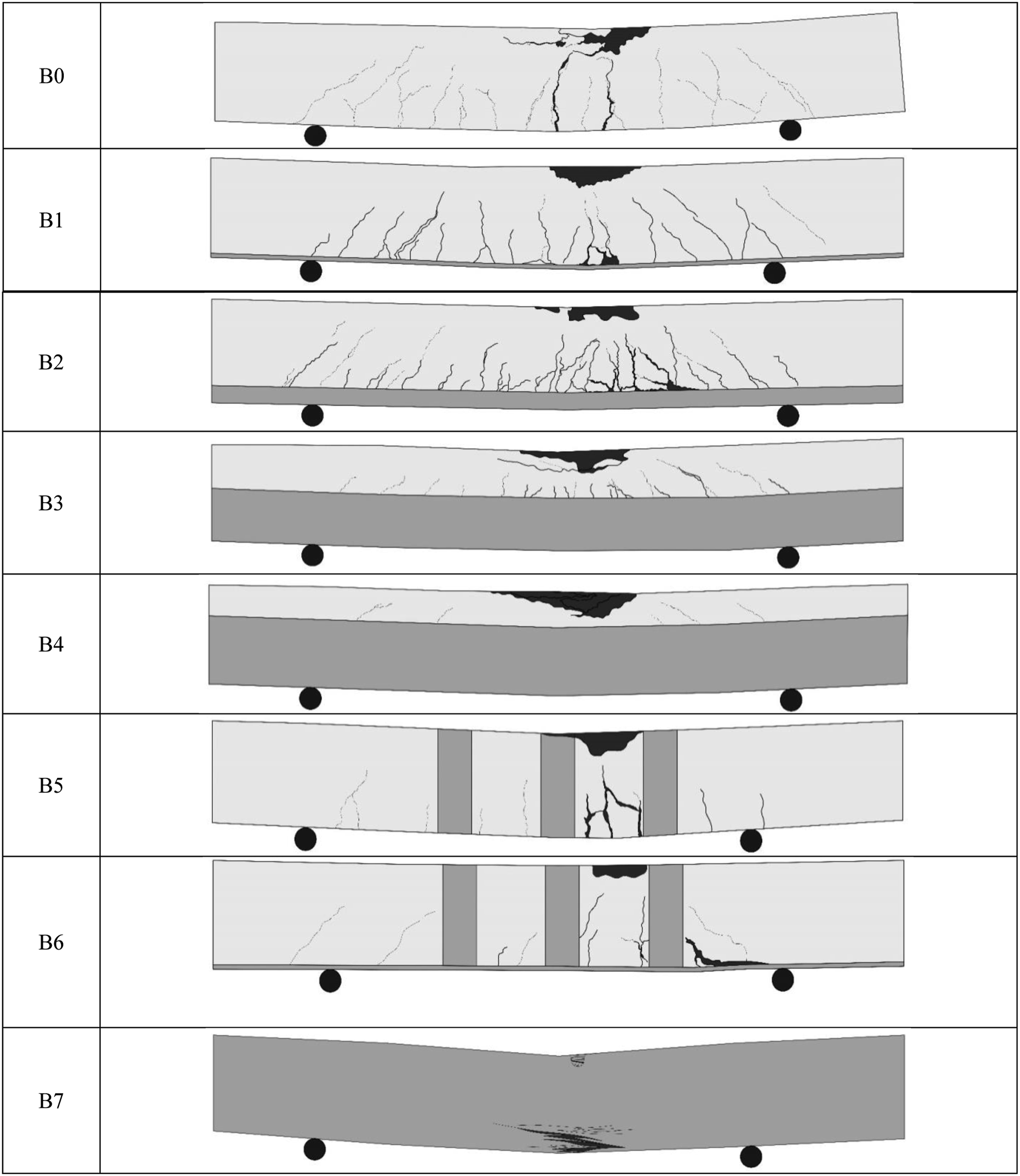
For the beam B1 with bottom layer of BFRP, the cracking behavior was similar to that of the reference beam B0. However, the first crack was observed at a higher load of 31 kN. The number of cracks was increased significantly at a load of 58 kN. Most of the cracks were flexural cracks, but higher number of shear-flexural cracks were observed along the shear span compared to the reference beam B0. Major cracking was observed at 69 kN, close to which a diagonal shear crack was observed at the outermost of one of the shear spans, however, the control cracking was flexural. The beam stopped absorbing any load higher than 72.56 kN, where partial debonding failure was observed in the tension zone accompanied by crushing of the top compressive zone and excessive flexural and shear-flexural cracking.
More cracks were observed in beam B2 compared to B0 and B1 where several flexural cracks were initiated, propagated upward and connected with the newly initiated cracks after the load was continued beyond the first cracking. The first crack was flexural and was observed at 29 kN. The spalling of the compression concrete was started at 52 kN load, while cracking sound of the BFRP laminates were heard at 29 and 57 kN, which was followed by more concrete spalling at 67 kN as shown in Figure 7. The BFRP laminate failed at 72.82 kN by interfacial debonding and loading was stopped after laminate failure.
For the beam B3 with BFRP sheet extended to half the depth of the beam sides, the crack visualization was postponed to a higher cracking load of 44 kN. The cracks were of course initiated at lower load, but no vision was allowed at the bottom surface and the bottom half of the beam. The partial debonding and tearing of the BFRP textile was started at a load of 69 kN, while subsequent tearing sounds were heard at 69, 71, and 72 kN. The concrete spalling started at 75 kN, at which significant tearing of the BFRP textile was recorded until reaching its ultimate at 76.55 kN with a very loud rupture sound. Partial peeling off and partial debonding failure were also occurred along the side vertical extensions of the BFRP as shown in Figure 7. Due to the same reason discussed for B3, which is the continuity of the BFRP fabric along the beams’ sides, the first cracking of beam B4 was noticeably postponed. The load at which the first crack was visually recorded was 63 kN, which is the ever higher among all beams. The Sound of BFRP cracking were also heard at loads of 69, 71, and 76 kN. This sound led to the failure of the beam at an ultimate load of 80.55 due to the partial debonding of the BFRP sheets along a smaller area extended along the beam’s mid-span (between the point loads), which was accompanied by concrete crushing in the compression zone as shown in Figure 7.
The beam B5 with vertical BFRP U-wraps along the flexural span showed similar behavior as the reference beam B0, where the failure followed the yielding of the tension steel reinforcement. Another notice is that this beam exhibited lower number of flexural cracks compared to all previously discussed beams as shown in Figure 7. The first visual crack was observed at a load of 35 kN, while more cracks were observed when the load reached 55 kN. Almost all cracks were vertical along the flexural zone with smaller few cracks within the shear span, which were also nearly vertical.
The beam B6, which is strengthened with a bottom layer of BFRP sheet as B1 in addition to vertical U-wraps of BFRP strips as in beam B5, showed an in-between behavior of those of B1 and B5 beams; where few flexural cracks were observed between the vertical U strips as in B5, but with some flexural shear cracks along the shear spans as in B1. The first crack was visually observed at a load of 43 kN. As load reached 54 kN, more cracks were recorded and the major cracking took place at 63 kN. The beam reached an ultimate load of 73.56 kN and failed by the debonding of the lower BFRP layer and concrete crushing in the compression zone. For the beam B7, the cracking could not be observed because the beam sides and bottom surface were fully covered with BFRP fabric. The cracking sound were heard when loading was applied. However, the sound of cracking and tearing of BFRP textile were heard along the test time until the beam was finally failed after reaching an ultimate load of 88.54 kN with blast-like sound. The beam failed by flexural failure, rupture of BFRP, and crushing of concrete between the loaded points as shown in Figure 7.
The above discussion shows that the crack propagation in strengthened beams differs from that of the reference one. This is an expected result as strengthened beams can withstand higher load capacities than their unstrengthened counterparts, which significantly affects their behavior under loading. The use of the BFRP sheets helped to better distribute the tensile stresses at the soffit of the strengthened beams, which resulted in reductions in the width and length of flexural cracks compared to the reference unstrengthened beam.
Load capacity and load-deflection behavior
Cracking, yield, ultimate, failure loads and failure mode.

aMode 1: Flexural failure, concrete crushing after the steel bars yielded. Mode 2: The beam flexural failure, concrete crushing with BFRP debonding and concrete crushing in the compression zone; Mode 3: The beam failed by flexural failure, crushing of concrete, rupture of BFRP and concrete crushing in the compression zone.
bThe beam B8 U shape wrapped therefor no cracks were observed.
Effect of bottom layer of BFRP
Figure 8 shows the load-deflection curves of the reference beam B0 and the beam B1, which is reinforced with a bottom layer of BFRP. It can be observed from the figure that as load increased deflection also increased in control beam. The comparison of the two figures shows that the load of B1 beam was higher than that of the reference beams B0 at the four stationary points, where at first crack, yield, ultimate, and failure loads, the capacity of B1 increased by approximately 63, 32, 36, and 37%, respectively, when compared to the control beam B0. The higher capacity of load is an expected result, which is attributed to the additional tension reinforcement area provided by the BFRP sheet at the extreme tension fiber. The post yielding drops in the load deflection curve of B1 shown in Figure 8 refers to the partial debonding or tearing of the BFRP sheet. As load increased beyond steel yielding, the previously initiated cracks tended to get wider, while more new cracks were initiated. A significant amount of tensile stresses across these cracks was transferred by the BFRP sheet as it worked as cracks arrester. The localization of high tensile stresses led to the rupture of BFRP or its debonding from the concrete surface. Such behavior is typical for FRP strengthening in flexure.
19
Load-deflection behavior of reference beam B0 and beam B1.
Effect of vertical extension of bottom layer of BFRP
The second group of beams investigates the influence of the vertical extension of the bottom layer of BFRP. Figure 9 shows the load-deflection curves of B0, B1, B2, B3, and B4 beams. It can be seen that the first crack, yield, ultimate and failure loads of the reinforced concrete specimens strengthening with BFRP sheets were enhanced in varying degrees. As a result, the first crack loads of the specimens B2, B3, and B4 beams were increased by approximately 53, 132, and 231%, respectively, as compared with that of the reference beam B0. Once the first cracks of the RC beam appeared, the BFRP sheets played a very important role in arresting the cracks carrying the high concentrated stresses transferred across the two faces of these cracks. Comparing B2, B3, and B4 beams with B0, the yield load capacity increased by approximately 28, 31, and 44%, respectively, while the ultimate load capacity increased by approximately 37, 44, and 52%, respectively, compared with B0. Finally, the failure loads of the beams B2, B3, and B4 were increased by 46, 53, and 61%, respectively, as compared to B0. Load-deflection behavior of beams B0, B1, B2, B3, and B4.
It is also worth mentioning that the beams with vertical extensions (B2, B3, and B4) retained higher ultimate and failure load capacities compared to B1 with bottom layer of BFRP, which leads to the conclusion that increasing the vertical extension of the BFRP results in higher load capacity of the strengthened beams. However, by simple comparisons, it is also obvious that using 25 mm vertical extension had no significant effect on the load capacity at cracking, yielding and ultimate stages compared to beam B1 (no vertical extension), while further extensions by 75 and 105 mm led to significant improvements in load capacity at all stages. This can be attributed to the extra reinforcement area in the tension zone provided by the higher extensions and the confinement of the BFRP wraps across the most depth of the section below the neutral axis. It is also noticed from the observation of Figure 9 that all beams with vertical extension of BFRP (B2, B3, and B4) exhibited strain hardening along almost the full post yield region, which reflects the superior crack arresting of BFRP wraps in these beams compared to the beam B1 without vertical extension. The continuous strain hardening behavior after steel reinforcement yielding and before the debonding or rupture of the FRP was recorded by previous investigations for beams strengthened externally with CFRP, GFRP, 37 and BFRP sheets. 38
The beams B3 and B4 exhibited more interesting behavior where larger deformations compared to reference beam B0 and beams B1 and B2 were recorded at ultimate load and at failure. The better performance of these beams is due to their load-deflection curve shapes. After the partial rupture of the BFRP (or partial debonding), represented by the partial post-yield drop and recovery of the load, the beams could withstand higher displacements up to failure than the reference beam B0. Many previous studies showed that FRP wraps reduces the ductility of the beams resulting in lower final displacements.21,25,37 However, multilayer FRP sheets were used in these studies, which resulted in apparently higher initial stiffness and lower ductility, while only one layer of BFRP was used in this study. Owing to the high ductility (higher percentage elongation) of BFRP, and the used moderate amount of BFRP (one layer of 0.3 mm thickness), a favorable behavior of larger load and deflection capacities was recorded. The obtained results of beams B3 and B4 support the findings of Li-Jun et al. 39 where the authors found that using one layer of BFRP led to higher load capacity and final deflection close to that of non-strengthened beam, while the increase of layers yielded significant load capacity improvement but apparently lower deflections, with this effect increased as the number of layers increased. Lihua et al. 21 reported that beams strengthened with two layers of BFRP exhibited better strength and ductility than those with only one layer, however, the thickness of the BFRP sheets was only 0.107 mm, while the used thickness in this study was 0.3 mm, which in result agrees well the findings of the current research.
This behavior can also be attributed to the ability of the longer vertical extensions of BFRP wraps to arrest the differential flexural cracking along the flexural zone and increase the shear strength along the shear zones. Thus, reducing the effect of shear stresses and allowing for more uniform flexural cracking. It is worth mentioning that the confinement of the vertical extensions of the wraps was moderate due to the use of single layer of FRP. Hence, the confinement is not as high to alter the failure from ductile tension failure to brittle compression failure as was recorded for beams strengthened with multilayers of wraps covering the full tension zone. 37
Effect of vertical U-wrap strips of BFRP
The third group was directed to evaluate the effect of vertical U-wrap strips of BFRP on the flexural behavior of reinforced concrete beams. Figure 10 shows the load-deflection curve of B0, B1, B5, B6, and B7 beams. The first crack, yield, ultimate, and failure loads for each specimen are given in Table 4. As shown by the measured values, the flexural capacity enhanced greatly for the beams strengthened by BFRP. Load-deflection behavior of reference beams B0, B1, B5, B6, and B7.
The first crack loads of beams B5 and B6 increased by 84 and 126%, respectively, compared with the first crack load of B0. Cracks were not visually observed in beam B7 due to the full coverage of bottom and side surfaces of the beam with BFRP wrap. The yield loads of beams B5, B6, and B7 were 10, 33, and 46%, respectively, higher than that of B0. The ultimate loads of the strengthened beams increased significantly compared with the control beam. The ultimate loads of B5, B6, and B7 increased by 9, 39, and 55%, respectively. Similarly, for the beams B5, B6, and B7, the failure loads increased by 8, 39, and 67%, respectively. The BFRP-strips strengthened beams achieved a substantial gain in the strength if compared with B0. This means that the yield load, ultimate load and failure load capacities of the beam B6 with bottom layer of BFRP and U wrap strips was almost equal to those of B1, which was also strengthened with a bottom layer of BFRP, but without U strip wraps, while those of B5 with U wraps were apparently lower than of beam B1. On the contrary, the full wrap of the bottom and side surfaces of the beam B7 led to significant increase in the yield, ultimate and failure load capacities, which agrees with observations of the previous section of side extension of BFRP wraps.
It is worth mentioning that beams with U strip wraps exhibited lower final deflections compared to both B0 and B1. This finding also agrees with the findings of Masoud et al. 34 who reported that using CFRP U wrap strips can increase the load capacity of strengthened beams compared to the unstrengthened one, while the great gain in load capacity was when these wraps were accompanied with tension sheets. This is attributed to the confinement provided by the U strip wraps that increase the bond between steel bars and surrounding concrete, the extra longitudinal stiffness provided by epoxy resin and the flexural enhancement provided by the tension sheets. 34
Ductility, stiffness and toughness
Several methods were used in literature to calculate the ductility of beams tested under flexure. The most widely used method is the deflection-based ductility, while energy-based ductility and curvature-based ductility were also introduced by previous researches. All these methods, however, agree on one definition of ductility, which is the maximum plastic displacement or energy or curvature the material can withstand compared to that at reinforcement yielding.

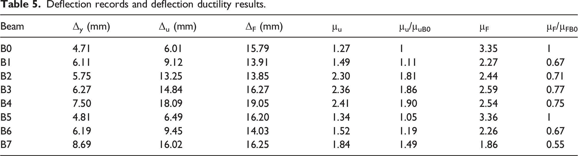
Deflection records and deflection ductility results.
Toughness and stiffness of the tested beams were also calculated in this research. Toughness is simply the calculated area under the load-deflection curve, which represents the displacement energy the beam can absorb at each level of loading until failure. Ty represents the energy absorption at the steel yielding stage that can also be termed as yield toughness, which is estimated by the integration of load-deflection curve up to the stage of yield load. Tu represents the energy absorption up to the ultimate load, or also can be termed as ultimate toughness, which is estimated by the integration of load-deflection curve up to the stage of ultimate load, while the term T represents the total toughness of the beams, which equals the total energy absorbed by the beam until failure.
Stiffness and toughness results.

Effect of bottom layer of BFRP
It is mostly agreed in literature that flexural strengthening of beams with externally bonded FRP sheets results in ductility reduction. Considering the slightly different behaviors obtained in this research and the adopted definitions of ductility, the same finding was obtained but using different definition. Many previous researches19,37,38 showed that beyond steel yielding, the deflection of FRP strengthened beams shows continuous strain hardening till the debonding or rupture of the FRP. Hence, the load continuous increasing with the deflection increase where failure load becomes equal to the ultimate load. This behavior is different than that of reinforced concrete beams where post yield strain hardening till the ultimate (or peak) load is followed by a full or partial phase of strain softening, where the failure load is lower than the peak load. Due to the superior ductility of the used BFRP in this research and the moderately low amount of BFRP used (one layer), some of the tested beams exhibited strain hardening followed by semi flat strain softening or partial strain softening phase. Consequently, the ultimate load was recorded between the yield and failure loads. Such a behavior was also observed for load-deflection curves of BFRP strengthened beams tested by previous researchers. 30 Therefore, considering the deflection corresponding to ultimate load to calculate the ductility, resulted in higher ductility indices compared to the unstrengthened reference beam. On the other hand, the ductility indices of BFRP-strengthened beams calculated based on the failure deflection were all lower than that of B0, which completely agrees with the vast of the available literature.
According to previous researchers,41,42 different definitions were introduced to distinguish the load at which the ultimate deflection is calculated for ductility estimation purposes of reinforced concrete beams. Some of which depended the load within the post ultimate zone that has a value of 80% of the ultimate load (maximum or peak load), while others depended 85–99% of the ultimate load.43–45 Others defined this load as the load at which the load value drops suddenly due to excessive flexural cracking or concrete compression crushing.46,47 For all, the purpose is to calculate the maximum possible plastic deformation the beam can withstand before failure. Therefore, the failure ductility used in this research much agree with this definition than the ultimate ductility. However, all are addressed for comparison purposes.
From Table 5 and Figure 11 it is shown that B1 with bottom layer of BFRP, the ultimate ductility increased compared to that of B0, where the ultimate ductility increased by approximately 11%. On the other hand, and as introduced in this section, the total plastic ductility is measured as the failure ductility, which decreased by approximately 33% compared to that of the control beam B0, which agrees with the findings of previous researchers.
25
On the other hand, Table 6 and Figure 12 show that the initial stiffness (Ky) of beam B1 was almost similar to that of the reference beam B0, where an increase of only 1% was recorded over the beam B0. This is attributed the increase in yield deflection of B1 (6.11 mm) compared to that of B0 (4.71 mm) although of the 32% increase of the B1 yield load over that of B0. For the same reason, the yield energy, which is also termed here as yield toughness (Ty) of B1 was approximately twice that of B0, while the total toughness increase of approximately 8% was recorded with comparison to B0. Ductility and normalized ductility of beams B0, B1, B2, B3, and B4: (a) ultimate ductility; (b) failure ductility. Toughness and normalized toughness of beams B0, B1, B2, B3, and B4.

Effect of vertical extension of bottom layer of BFRP
As shown in Table 5 and Figure 11a, the ultimate ductility of beams B2, B3, and B4 were all higher than those of B0 and B1, where µu increased by 81, 86, and 90%, respectively, compared to B0. These values are expected ones as these beams retained their ultimate (maximum) loads at much higher deflections than those of B0 and B1 as shown in Table 5. However, as discussed above, the failure ductility (µF) reflects the actual plastic ductility used for engineering applications. Table 5 and Figure 11b show that these values were lower than that of B0 and were of comparable values. The failure deflection ductility of beams B2, B3, and B4 decreased by 28, 23, and 25%, respectively, compared to B0.
Table 6 and Figure 12 show that the toughness of beams B2, B3, and B4 exhibited continuous increase with the increase of BFRP vertical extension. This is obviously attributed to the significant increase in the area under the load-deflection curve due to the higher retained yield, ultimate, and failure load capacities. The toughness of B2, B3, and B4 was increased by 15, 42, and 78%, respectively, as compared to B0. Interestingly, the highest toughness percentage value was observed in the specimen B4 which was strengthened with BFRP having the deepest vertical extension of BFRP of 105 mm. This beam retained the highest load capacities and the highest final deflection. Hence, it can be concluded that toughness increases as the vertical extension of the full U wraps increases within the tension zone of the beam below the neutral axis, or slightly above it.
As for B1, the yield loads of beams B2 to B4 were higher than that of B0, but they were comparable to that of B1. Considering the moderately higher deflection at this stage for beam B2 (5.75 mm) and the noticeably higher ones of beams B3 and B4 (Table 5), the initial stiffness of the beam B2 was comparable to that of B1 with an increase over beam B0 of 5%, while Ky values of beams B3 and B4 showed 2–10% decrease compared to B0.
It can be observed in Figure 13 that the initial stiffness of beams B2 and B3 increased by approximately 7 and 1%, respectively, compared to B0. As their yield load values were higher than that of B0 by approximately 10 and 34%, respectively, their yield deflections were also higher. On the other hand, the stiffness of the beam B4 decreased by approximately 21% due to the significantly higher yield deflection although of the gain in yield load compared to B0. Stiffness and normalized Stiffness of beams B0, B1, B2, B3, and B4.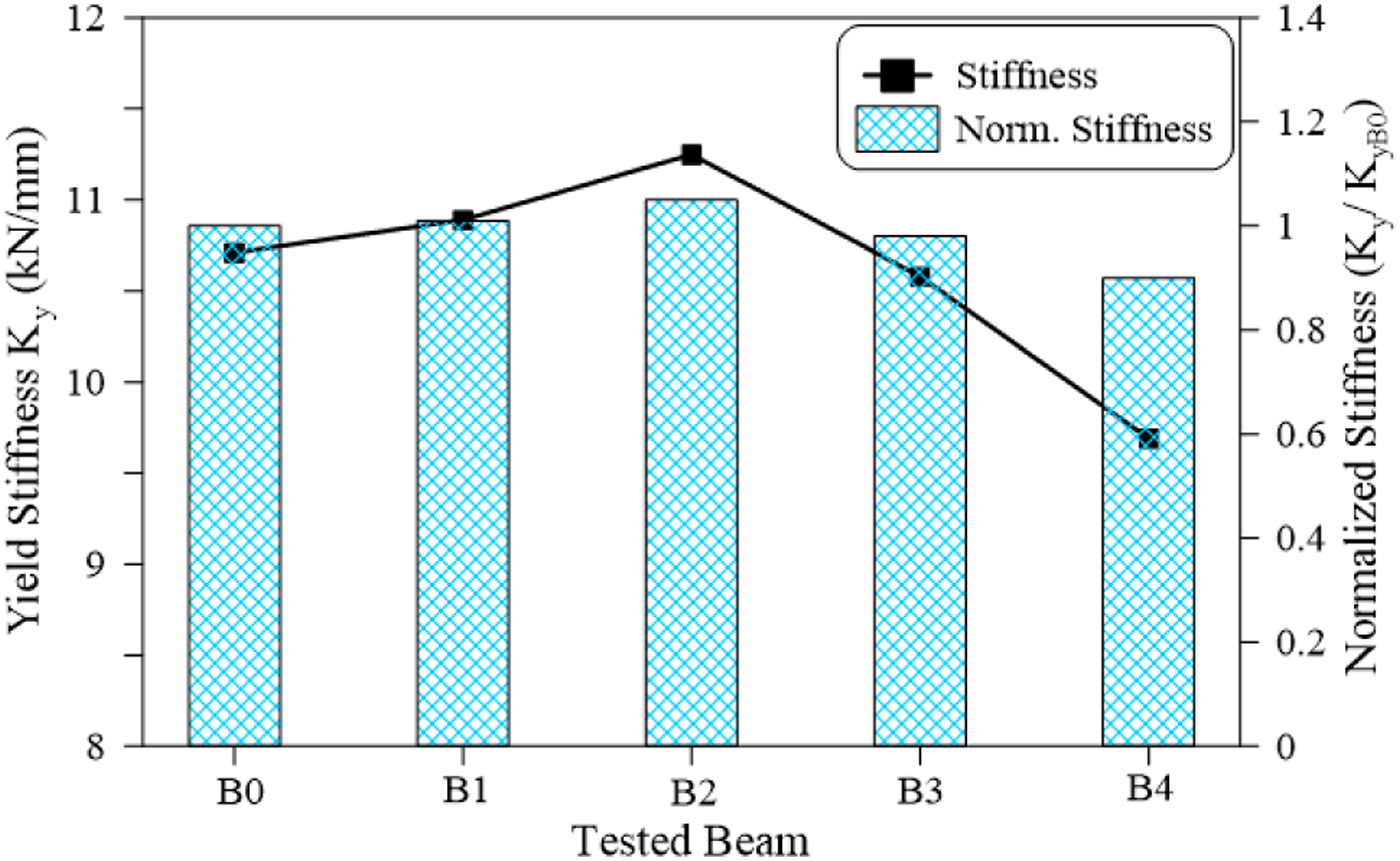
Effect of vertical U-wrap strips of BFRP
Figure 14 presents the effect of vertical BFRP wrap strips on the ductility of the strengthened beams. It is obvious from Figure 14a that the beams B5, B6, and B7 exhibited higher ultimate ductility indices compared to B0, while the failure ductility of beams B6 and B7 were significantly lower than that of B0. The ultimate deflection ductility indices of beams B5, B6, and B7 were 5, 19, and 49% higher than that of B0, respectively, while their failure deflection ductility indices were lower by approximately 1, 33, and 45%, respectively. However, it is obvious in Table 6 and Figure 15 that the toughness values of these beams were higher than the reference beam B0 by 12, 14, and 53%, respectively, as compared to B0. The increase in toughness can be attributed to the larger load capacities of these beams at yield, ultimate and failure stages. Ductility and normalized ductility of beams B0, B1, B5, B6, and B7 B4: (a) ultimate ductility; (b) failure ductility. Toughness and normalized toughness of beams B0, B1, B5, B6, and B7.

It can be observed in Figure 16 that the initial stiffness of beams B5 and B6 increased by approximately 7 and 1%, respectively, compared to B0. As their yield load values were higher than that of B0 by approximately 10 and 34%, respectively, their yield deflections were also higher. On the other hand, the stiffness of the beam B7 decreased by approximately 21% due to the significantly higher yield deflection although of the gain in yield load compared to B0. Stiffness and normalized Stiffness of beams B0, B1, B5, B6, and B7.
Conclusions
This study presents the experimental performance of reinforced concrete beams strengthened with BFRP. Seven beams were strengthened with different BFRP application configurations, while the eighth beam was kept without strengthening as a reference beam. The experimental results showed that the external bonding of BFRP sheets is an effective strengthening method for enhancing the flexural strength of reinforced concrete beams. Based on the obtained experimental results and within the limitations of the investigated parameters in this study, the following conclusions can be drawn. 1. The use of one layer of BFRP with 0.3 mm thickness along the extreme tension fiber of reinforced concrete beams could increase the capacity of beams against cracking by not less than 50%. Similarly, the yield capacity of the beams was increased by at least 28%. The increase in cracking capacity is attributed to the crack arresting potential of the BFRP sheet that can withstand high tensile stresses across these cracks, which delays their propagation. The increase in yield strength is due to the added reinforcement area by the BFRP owing to the perfect bond between the BFRP and concrete. The ultimate strength of the beams strengthened with a soffit layer of BFRP was also significantly improved compared to the reference beam without strengthening. The retained ultimate load capacity of beams strengthened with one layer of BFRP with 0.3 mm thickness along the extreme tension fiber was improved by approximately 37–51%. 2. In spite of the development in yield load capacity of the strengthened beams, their initial stiffness values were comparable to that of the reference beam. The initial stiffness of beams strengthened with a bottom layer of BFRP were 90–105% of that of reference beam B0. This slight increase or decrease in the stiffness of the strengthened beams is attributed to their higher recorded deflections at yield stage, which reduced the calculated stiffness although of its apparent higher values. 3. The cracking, ultimate, and failure loads of beams strengthened with a bottom layer of BFRP increased continuously with the increase of the layer vertical extension length along the side surfaces of the beams. For bottom layers of BFRP with vertical extensions of 25, 75, and 105 mm, the ultimate strength of the beams increased by 37, 44, and 52%, respectively, compared to the reference beam B0. The failure deflections of these beams followed a similar trend of increase with the increase of the vertical extensions, where their recorded deflections at failure were 13.85, 16.27, and 19.05 mm, respectively. 4. The ductility of the beams strengthened with one bottom layer of BFRP (based on the failure deflections) was in general lower than that of the reference beam. However, it was higher for beams with vertical side extensions than that of beam B1 where the BFRP layer was applied on the soffit only. The failure ductility of B1 was 33% lower than that of B0, while those of beams B2, B3, and B4 (with vertical side extensions) were lower than that of B0 by 25–29%. 5. The beams strengthened with BFRP U-wrap strips retained higher load capacities at cracking, yield, ultimate, and failure stages than those of B0. However, much better load capacity gains were obtained when BFRP U-strips were applied with the bottom layer of BFRP. The ultimate load capacity of B6 with bottom layer and U-strips of BFRP was approximately 39% higher than that of B0, while the ultimate capacity of B5 (with U strips) was only approximately 10% higher than that of B0. This is attributed to the added reinforcement area provided by the layer of BFRP along the extreme tension fiber of B6. On the other hand, and for the same reason, the ductility of B5 was higher than that of B6. 6. The toughness of all beams strengthened with BFRP sheets increased compared to the reference beam B0. This increase was higher as the side vertical extension of the bottom layer was increased. The toughness values of beams B1, B2, B3, and B4 were 8, 15, 42, and 78% higher than that of B0, respectively.
Footnotes
Declaration of conflicting interests
The author(s) declared no potential conflicts of interest with respect to the research, authorship, and/or publication of this article.
Funding
The author(s) received no financial support for the research, authorship, and/or publication of this article.