
Abstract
In traditional processing mode, a given lathe and a set of fixed processing system can only produce a predetermined precision part. This article proposes a machining method that can control the surface precision of machining plane parts, and four gaskets with different accuracy requirements are processed on the same slow tool servo single-point diamond lathe for experimental verification. Then, the Peak Village (PV) value and surface topography of the processed parts were measured using the surface profiler Taylor Hobson PGI 1240 and Keyence VR-3200, respectively. Through the processing and analysis of the measured data, the maximum deviation between the PV value and the given PV value is 2.4 µm, the minimum deviation is 0.4 µm. And the PV value obtained by calculating the helical spacing measured by surface topography according to the method in this article is approximately equal to the measured PV value, so the correctness of the machining method is verified. Therefore, the machining method can control the surface accuracy of machining parts accurately according to the required accuracy.
Introduction
The surface accuracy of machining parts is one of the most important points in the field of machining. Because the surface accuracy of machining parts has an important impact on the performance of parts, such as friction coefficient, wear resistance, and service life. Therefore, many scholars have done a lot of research on machining surface accuracy of machining parts. With the progress of machining technology and theory, the surface accuracy of machined parts has been able to reach the nanometer level. 1 But in the actual application of mechanical parts, it is not the higher the surface accuracy is, the better the performance of the part will be. In friction parts, it is not the smoother the part is, the lower the friction coefficient of the friction pair will be. 2 In some experiments, it is necessary to study the control variables of parts with different surface accuracy. Therefore, a method is needed to control the surface machining accuracy of parts and realize the machining of parts with different accuracy requirements.
For a long time, much research on the surface machining accuracy has focused on how to improve the surface machining accuracy of parts, or how to realize the high-accuracy machining of some complex surfaces. Hao Wen et al. proposed an improved mesh offset intersection algorithm to reduce the influence of tessellation error, the error is a major cause of the machining surface defects. They calculated the cutter location points from the vertices firstly, then they smoothed the tool path in two perpendicular directions. Through this improved mesh offset intersection (MOI) algorithm, they have significantly improved the machining accuracy and avoided surface defects. 3 WB Lee et al. presented a compensation method for the correction of the residual form error caused by tool decentering in aspheric surfaces ultraprecision machining. The method modifies the numerical control (NC) machine code generated by a tool path generator software (DIFFSYS v.3.80) by utilizing the form measurement data from a Form Talysurf system (Taylor Hobson Company, Leicester, England) in an ultraprecision single-point diamond turning (SPDT) lathe. The residual form error is obviously reduced with the use of this compensation technique. 4 Ji-Hun Jung et al. analyzed machine tool errors in the workspace by using parametric error models. And they proposed an online measurement and error compensation method to improve the machining accuracy. 5 Yuetian Huang et al. proposed the combination of SPDT and ion beam figuring (IBF) to obtain the high-precision surface. Their experiments proved that IBF can reduce surface roughness by removing the turning marks. 6 M Tauhiduzzaman et al. found that the form error was critical facts in designed optical system. The imbalance of the spindle was a major cause of form error. By theoretical and experimental analysis, it was found cutting material and tool geometry had no influence on the spindle star error, while the spindle star error is affected by the inherent characteristic of air bearing. 7 Shijun Ji et al. analyzed two ultraprecision machining methods for off-axis paraboloid and proved that the paraboloid obtained by machining the cylindrical workpiece around the paraboloid axis has better surface quality. 8 Zhiwei Zhu et al. proposed an adaptive tool servo diamond turning method for improving the surface quality and machining efficiency. By using this method, they accomplished the ultraprecision machining of general surface and took the processing of sinusoidal surface as an example for experimental verification. 9 Shijun Ji et al. proposed a method to generate tool point trajectories according to the requirements of forming precision. They converted the tool path to the x–z plane then used the chord error to control the accuracy of the surface. But they did not consider the effect of residual height between the two tools tracks. 10 As can be seen from the above, many researchers pay attention to how to improve the machining accuracy and the formation of complex surfaces. There is still no research on how to get a surface with the required form accuracy.
This article presents a machining method of processed parts with controllable surface precision based on the reverse thought of single-point diamond cutting. The related SPDT principles and trajectory planning methods used in this method are proposed in the “Basic theory and trajectory generation method” section. Verification experiment and detection are described in the “Experiment and detection” section. Experimental results and error analysis are shown in the “Measurement results and analysis” section. Extending the reverse thought is presented in the “Extend the reverse thought” section. Conclusions and expansion are given in “Conclusions” section.
Basic theory and trajectory generation method
The principle of SPDT
Common diamond turning methods can be divided into slow tool servo machining and fast tool servo machining. This article takes slow tool servo turning as an example. The machining principle of slow tool servo turning is shown in Figure 1.

Schematic diagram of slow tool servo turning.
The cutter sweeps over the surface of the rotating workpiece to form the machined surface. Therefore, the workpiece surface of SPDT may produce some periodic surface microstructures. Figure 2 shows the cross-section outline along the radial direction of the surface of turning parts. For machined parts, the maximum height of these residual microstructures can be used as a measure of the surface accuracy of machined parts.

Theoretical cross-section profile of single-point diamond turning workpiece.
The microstructure’s height of the workpiece surface after SPDT is related to the feed rate and tool nose radius. When the tool rake angle is equal to 0°, the maximum height of the surface residual microstructure (residual height) is calculated as shown in Figure 3.

Calculation model of surface residual height.
where h is the residual height, S is the distance between the two adjacent cutter points, for plane machining, it is the feed rate of X-axis, and R is the radius of turning tool tip. According to the geometric relation, the residual height can be expressed as

Method of machining trajectory generation
By using the reverse thought of the forming principle of SPDT, different parts with required accuracy can be machined on the same lathe through the planning of machining trajectory, so the generation method of the tool path has been studied. At present, the machining trajectory of SPDT is spiral trajectory. There are two main methods to generate spiral trajectory, namely the constant angle method and the constant arc length method. The constant angle method, as the name implied, the central angle between any adjacent two points on the plane on the same circle is equal. The constant arc length method refers to the arc length between any adjacent two points on the same circumference of a spiral line on a plane is equal.
However, both methods have obvious disadvantages. For the constant angle method, the cutting points are densely distributed at the center of the trajectory, but sparsely distributed at the edge, which results in high machining accuracy in the middle part of the processed workpiece and low machining accuracy at the edge. On the contrary, the constant arc length method has a sparse distribution of cutting points in the center of the track and a dense distribution on the edge of the track, which leads to a low machining accuracy in the central part of the processed part and a high machining accuracy in the edge part of the processed part.
Both trajectory generation methods will lead to uneven distribution of machining surface precision, and the disadvantages of the two methods can be complementary. Therefore, this article adopts the method of combining the constant angle method and the equal arc length method to generate the machining trajectory.
The specific path generation method is shown in Figure 4, the central part of the trajectory is generated by the constant angle method, and the edge part of the trajectory is generated by the constant arc length method. The combined position of the two methods is that the arc length generated by the constant angle method is equal to the arc length given by the constant arc length method.
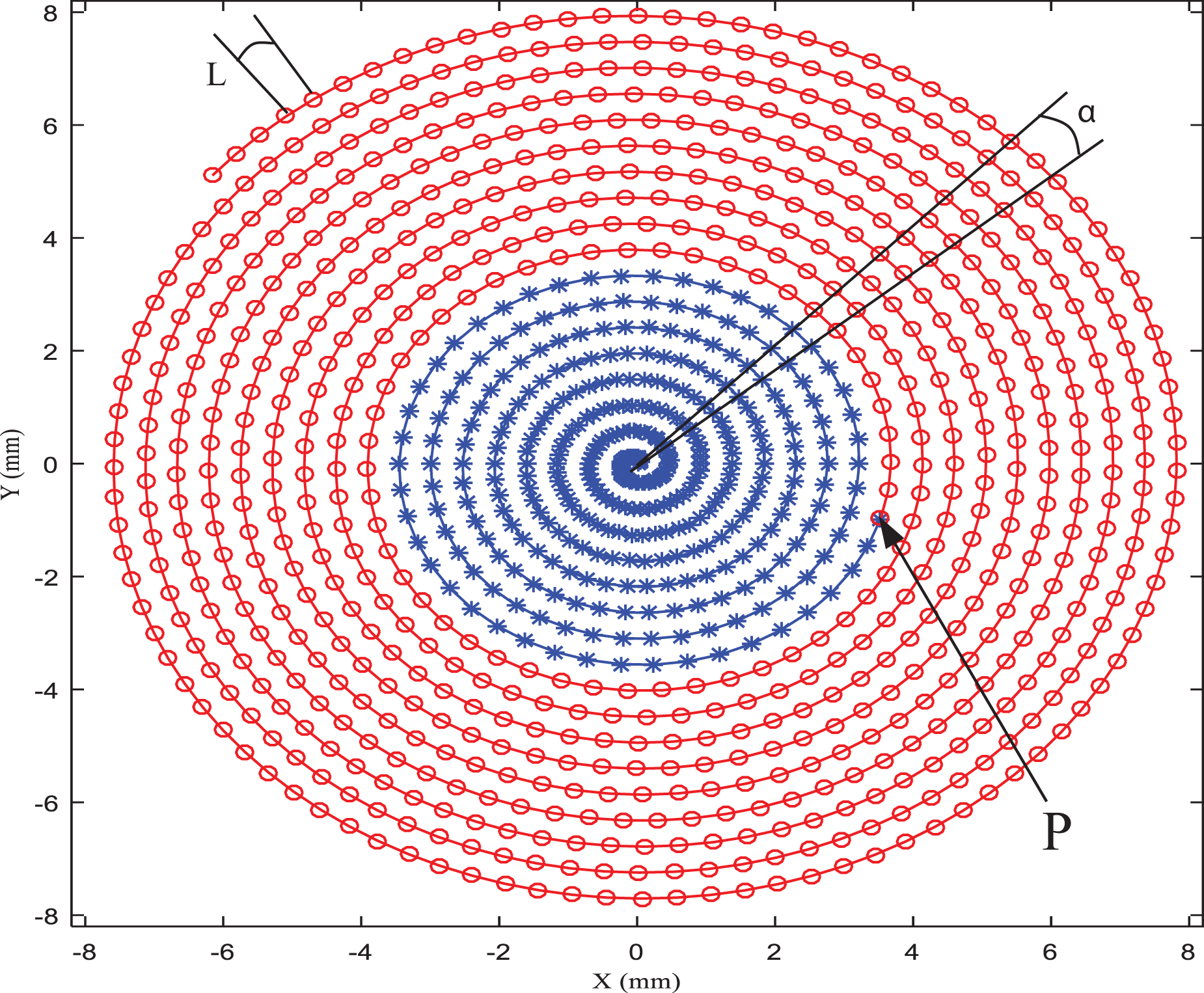
Trajectory generation method combining constant angle and constant arc length.
The spiral curve of plane machining trajectory adopted in this article is a curve based on Archimedes spiral and machining parameters. The equation of spiral machining path can be expressed as
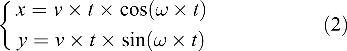
where v is the feeding speed of the X-axis and t is the time parameter. The value of t determines whether the spiral trajectory is generated by the constant angle method or the constant arc length method. When t is constant, the spiral trajectory is generated by the constant angle method, which is the blue area in Figure 4. When arc length L is constant, the spiral trajectory is generated by the constant arc length method, which is the red area in Figure 4, and in this case the equation for solving t is that
While, ω is the angular velocity, which depends on the given feed speed v, the radius R of the maximum external circle of the processed surface of the turning workpiece, and the number m of turns of the spiral path, ω is calculated as

And m is determined by the X-axis feed rate S and the radius R of the maximum external circle of the processed surface of the turning workpiece

According to the principle of SPDT described in “The principle of SPDT” section, the feed rate S in the direction of X-axis is related to the residual height h of the parts after machining. For plane machining, the distribution of spiral machining trajectories is also plane, so the spiral spacing generated by equation (4) is equal. That is to say, in the machining process driven by the trajectory, the feed rate S along the X-axis direction at all places on the plane is also equal, and the value of S is equal to the spacing of spiral trajectories. Therefore, the theoretical residual height can be calculated after plane machining. Starting from the reverse direction, given the machining accuracy requirements of the machining plane and machining plane is taken as the base plane, then the required accuracy of the turning spiral trajectory can be calculated from equations (1) to (4)
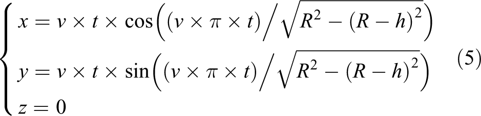
The spiral trajectory calculated by equation (5) is the cutting point trajectory of the contact between the turning tool and the machining plane, that is, the tool contact points trajectory. However, the turning trajectory points controlled by the control system of single-point diamond lathe are the center of turning tool tip, that is, the center of turning tool tip arc, which is called the cutter location points trajectory. Therefore, it is necessary to compensate for the tool nose radius of the turning trajectory points above in the direction of the normal vector of the cutting plane. For plane machining, the normal vector direction of the cutting plane is Z-axis direction, so the cutter location points can be expressed as
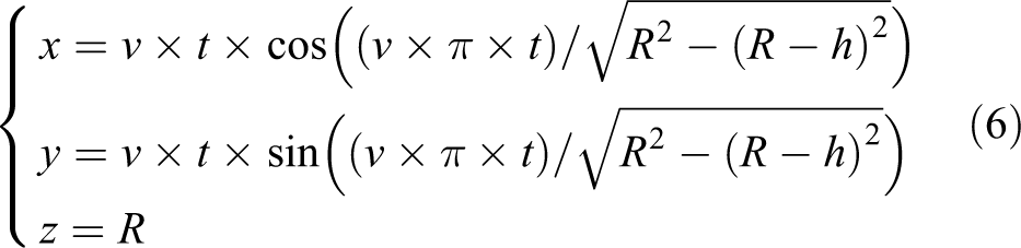
According to the above method, the SPDT trajectory of planar parts with required surface accuracy can be generated. Figure 5 shows the turning trajectory diagram generated according to a certain accuracy.

Diagram of turning trajectory.
In this section, the principle of SPDT and the machining method that can control the machining surface accuracy of the processed parts are described in detail. The verification experiment of the method is completed in the following section.
Experiment and detection
In this article, the machining method proposed above is verified by the machining experiments of four gaskets with different surface accuracy required by the experimental requirements of a research institution. The material of the processed gaskets is Al6061, the processing surfaces are required to be upper and under surfaces, and the roughened workpiece is the annular workpiece after rough machining on an an ordinary computer numerical control (CNC) lathe. The accuracy of the workpiece after rough machining operations is about 30 µm, and then the workpiece is machined on the ultraprecision turning machine. The dimension parameters of gaskets required for processing are shown in Table 1.
Machining gaskets parameters.

PV: Peak Village.
The geometric parameters of the tool used in the processing experiment are listed in Table 2. The cutting tool is selected by the tool rake angle, tool clearance angle, tool wrap angle, and tool nose radius. If the tool rake angle of the tool is too large, it will interfere with the surface to be machined. The interference between the tool surface and the machined surface will occur when the tool clearance angle is small. And the larger the wrap angle, the longer the effective cutting edge length. Besides, the tool nose radius should be less than the curvature radius at each machining point. The selection of the four geometric parameters should satisfy the condition that the tool will not interfere with the workpiece. The ultraprecision turning machine used in the processing experiment is Nanoform 250 (Precitech Company, Keene, New Hampshire of the United States) and the main parameters of each axis are listed in Table 3. The tool coating is not used, the coolant produced by Briggs & Stratton Company (Milwaukee, Wisconsin of the United States) was used in this experiment. The trial was repeated three times. According to the dimensional parameters and accuracy requirements of machining gaskets and the machining method described in the “Basic theory and trajectory generation method” section, the corresponding gasket trajectory generation is completed. The feed rate S along the X-axis corresponding to the processing of gaskets with different accuracy calculated by equation (1) is listed in Table 4. Cutting parameters of experiments are listed in Table 5.
Main parameters of the cutting tool.

Main parameters of each axis of the machine tool.

Corresponding feed rate of gaskets with different accuracy requirements.

PV: Peak Village.
Cutting parameters of experiments.

In order to improve machining accuracy, centering adjustment of diamond cutter and dynamic balance adjustment of spindle are required before turning experiment. The adjustments can be done through Nanoform 250’s own instruments and systems. After the adjustments were completed, different turning trajectory points generated by the proposed method were introduced to carry out machining experiments of gasket with corresponding accuracy. The turning process is shown in Figure 6.

Diagram of turning process.
The Peak Village (PV) values of upper and under surfaces of gaskets were measured by the surface profiler Taylor Hobson PGI 1240 (Taylor Hobson Company, Leicester, England) for processed parts. Figure 7 shows the measurement process of PV values. In addition, the upper and under surface topography of the processed gaskets was measured by Keyence VR-3200 (Keyence Company, Osaka, Japan) and the measurement process is shown in Figure 8.
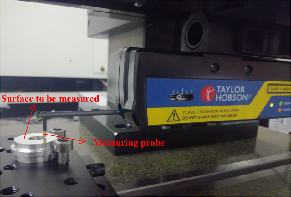
Photo of PV value measurement process. PV: Peak Village.

Photo of surface topography measurement process.
Measurement results and analysis
PV value measurement results and analysis
As can be seen from the measurement process of PV value shown in Figure 7 in the “Experiment and detection” section, the PV value of the workpiece was measured after it was separated from the fixture. Therefore, the measured data would be inclined as a whole, and the measurement results should be rotated to some extent.
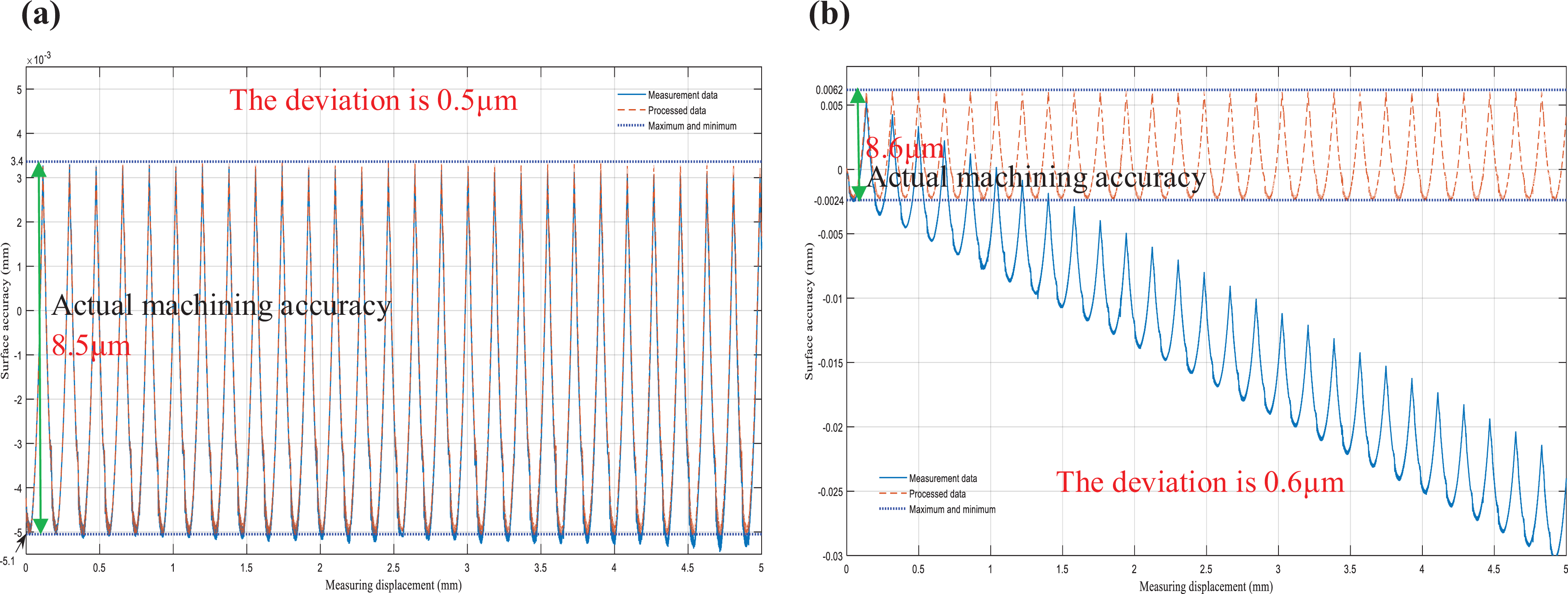
Figures 9 to 12 show the measured data curves of PV values of the plane processed in accordance with the requirements of various accuracy and the data curves after processing. As can be seen from Figures 9 to 12, the PV values of the measured gasket surfaces are analyzed to find that the deviation between the actual machining accuracy and the required accuracy is 2.4 µm, 0.9 µm, and 0.6 µm, respectively, when the accuracy is set to 28 µm, 18 µm, and 8 µm; when the accuracy is set to 2 µm, the deviation between the actual machining accuracy and the required accuracy is 0.4 µm.

PV value measurement data diagram of gasket surface (28 µm). PV value measurement data diagram of (a) upper surface of gasket and (b) under surface of gasket. PV: Peak Village.

PV value measurement data diagram of gasket surface (18 µm). PV value measurement data diagram of (a) upper surface of gasket and (b) under surface of gasket. PV: Peak Village.
PV value measurement data diagram of gasket surface (8 µm). PV value measurement data diagram of (a) upper surface of gasket and (b) under surface of gasket. PV: Peak Village.

PV value measurement data diagram of gasket surface (2 µm). PV value measurement data diagram of (a) upper surface of gasket and (b) under surface of gasket. PV: Peak Village.
At the same time, as can be seen from the diagram, the higher the setting accuracy, that is, the smaller the value of the required accuracy, the smaller the fluctuation interval of the measured data. This indicates that the more turning point of the spiral trajectory and the smaller the feed rate S, therefore, the control of the feed rate S can control the machining accuracy, it also proved the above method of controlling machining surface accuracy.
According to the calculated data above, the relationship curve between the accuracy deviation and the required accuracy is drawn, as shown in Figure 13. It can be seen from the figure that the larger the value of the required accuracy is, the larger the accuracy deviation will be. When the value of the required accuracy is smaller, the deviation of the machining accuracy is not smaller, but tends to be stable. This is because the machine tool movement error and fixture clamping error and other systematic errors will lead to a deviation that cannot be eliminated, so the machining accuracy deviation has a minimum value, and cannot be decreased. Therefore, if we want to reduce the accuracy deviation and control the machining accuracy more accurately, we need to use more accurate machining equipment and related machining systems.
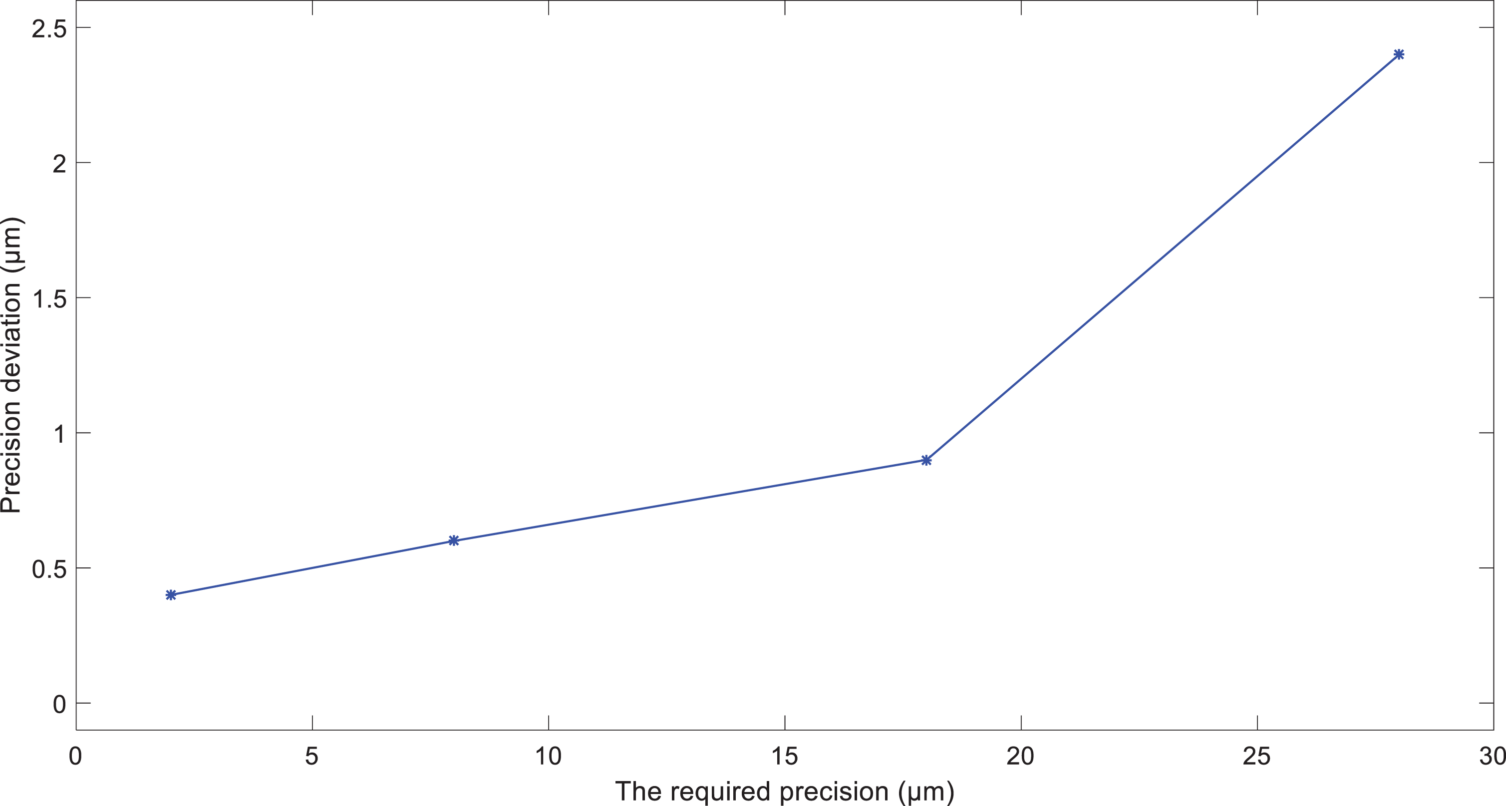
The relation curve between accuracy deviation and required accuracy.
Measurement results and analysis of surface topography of processed gaskets
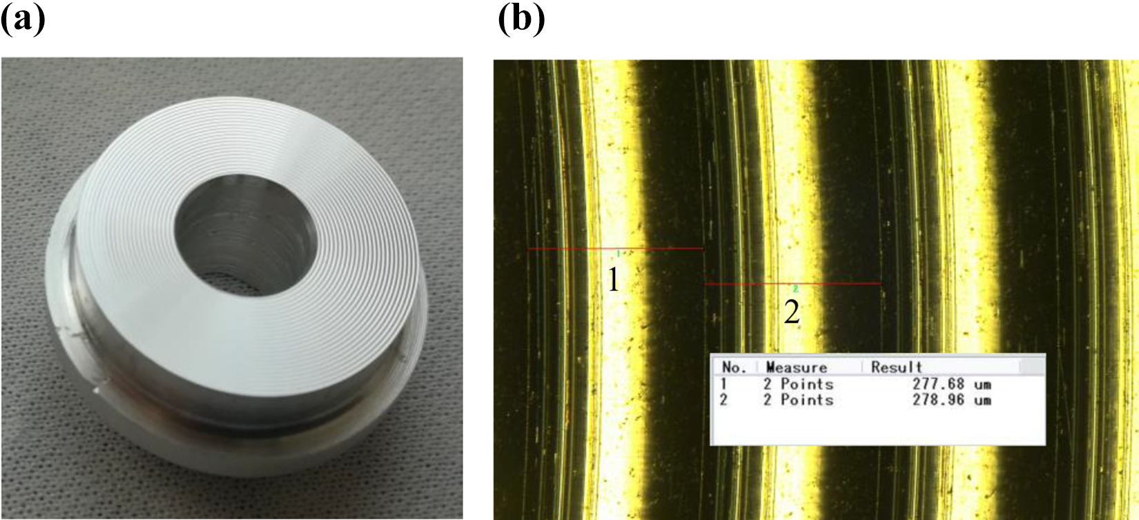
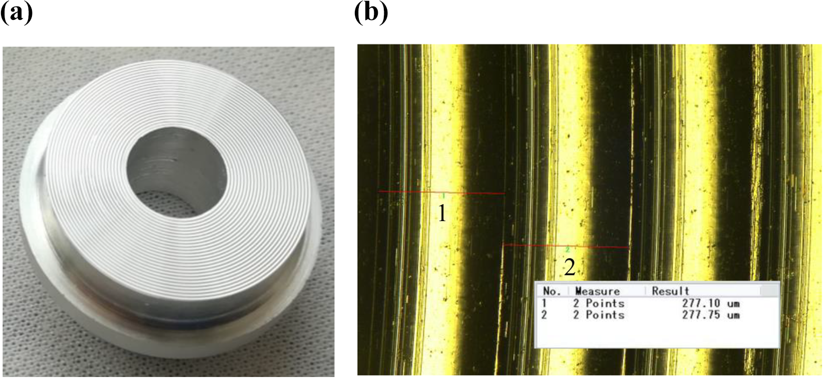
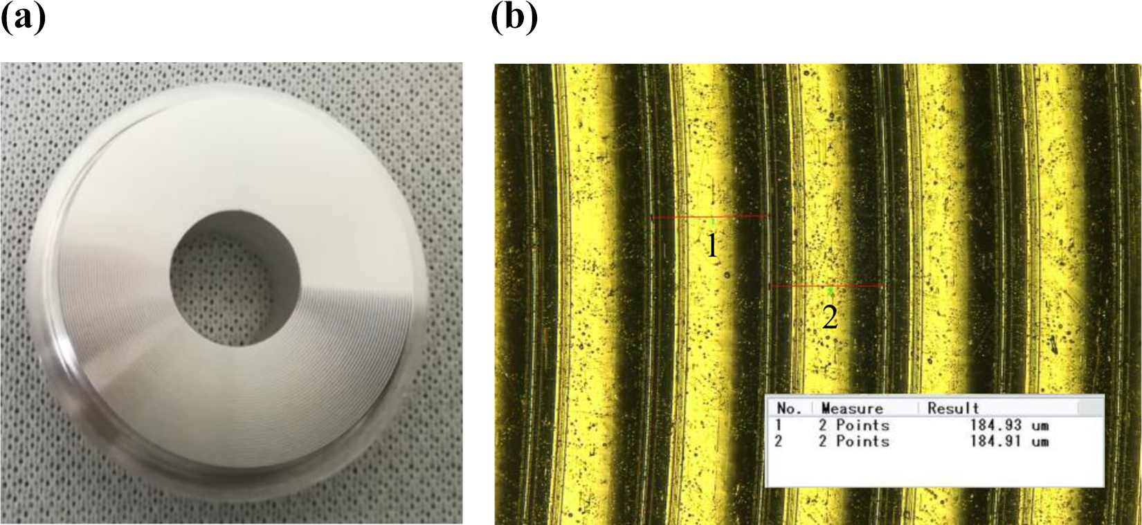
Figures 14 to 21, respectively, show the physical photos of upper and under surface of each gasket after machining and the surface topography measured by Keyence VR-3200.

Machined and measured result of upper surface of gasket (28 µm). (a) Physical photo of upper surface of gasket. (b) Measured diagram of machining trajectory spacing on upper surface of gasket.

Machined and measured result of under surface of gasket (28 µm).(a) Physical photo of under surface of gasket. (b) Measured diagram of machining trajectory spacing on under surface of gasket.
Machined and measured result of upper surface of gasket (18 µm). (a) Physical photo of upper surface of gasket. (b) Measured diagram of machining trajectory spacing on under surface of gasket.
Machined and measured result of under surface of gasket (18 µm). (a) Physical photo of under surface of gasket. (b) Measured diagram of machining trajectory spacing on under surface of gasket.
Machined and measured result of upper surface of gasket (8 µm). (a) Physical photo of upper surface of gasket. (b) Measured diagram of machining trajectory spacing on under surface of gasket.

Machined and measured result of under surface of gasket (8 µm). (a) Physical photo of under surface of gasket. (b) Measured diagram of machining trajectory spacing on under surface of gasket.

Machined and measured result of upper surface of gasket (2 µm). (a) Physical photo of upper surface of gasket. (b) Measured diagram of machining trajectory spacing on under surface of gasket.

Machined and measured result of under surface of gasket (2 µm). (a) Physical photo of under surface of gasket. (b) Measured diagram of machining trajectory spacing on under surface of gasket.
It can be seen from the measured surface topography and physical photos of under surface of gasket, the surface topography of the processed gasket is basically consistent with the expected surface topography. In order to further verify the correctness of the processing method proposed in this article and determine the reasons for the deviation of PV value, the values of feed rate S corresponding to the machining of gaskets with different accuracy calculated by equation (1) are compared with the measured thread spacing.
Figure 22 shows the data comparison between the feed rate (theoretical helical spacing) calculated by theory and the actual helical spacing after machining for gaskets with different accuracy. It can be seen that there is a deviation between the spiral trajectory spacing generated by actual machining and that set by theoretical calculation.

Comparison chart of theoretical and measured helical spacing values.
Based on the above experimental measurement results, we can see that the workpiece after machining is consistent with the given accuracy by the method that can control the surface accuracy of planar parts proposed in this article. And the application of trajectory planning plays a significant role in controlling the accuracy of machining surface. However, there is still some deviation between the required accuracy and the actual machining accuracy. It can be seen from equation (1) that the spacing of spiral trajectory has an important influence on the residual height of the machined surface. Therefore, the difference between the actual spacing of spiral trajectory and the theoretical spacing of spiral trajectory is the main reason for the deviation between the measured PV value and the required PV value. The actual spacing is larger than the theoretical spacing, resulting in the PV value of the machined surface being larger than the required PV value. Furthermore, the measured spacing of spiral trajectory was substituted into equation (1) to calculate the corresponding residual height which was approximately equal to the measured PV value. This proves the correctness of the theory of controlling accuracy proposed in this article and also verifies the speculation of the reason for accuracy deviation. Therefore, in the application of the surface accuracy control method for machining plane parts, if the higher the required accuracy of the machining surface is, the higher the motion accuracy of the machine tool and the positioning accuracy of the fixture should be, so as to achieve the required surface accuracy of the machining parts better.
Extend the reverse thought
The reverse planning thought can be extant from a plane to a curve surface. When turning plane, there is only one error as shown in Figure 23, which is residual error. When turning free surface, there are two kinds of errors which are residual error and chord error, respectively, as shown in Figure 24. The chord error is divided into two cases: cutting convex surface and cutting concave surface. The combination of the two errors is the total error. The corresponding calculation equations of total error are as follows: Total error of cutting convex surface Total error of cutting concave surface


Turning a plane using reverse designed thought.

Turning a curve surface using reverse designed thought.
The precision control method used in this article is to control the residual error in the turning plane. As for a free surface, it needs to control the total error, the residual error is just one part of the total error.
Conclusions
In this article, a planar machining method that can control the accuracy is proposed. And several groups of gaskets with different surface accuracy requirements were machined on a single-point diamond lathe of slow tool servo for experimental verification. Based on the findings above, the following conclusions can be drawn: The machining trajectory is generated by combining the constant angle method and the equal arc length method. The central part of the trajectory is generated by the constant angle method, and the edge part of the trajectory is generated by the constant arc length method. The combined position of the two methods is that the arc length generated by the constant angle method is equal to the arc length given by the constant arc length method. The results of the measurements are that when the accuracy is set to 28 µm, 18 µm, 8 µm, and 2 µm, the deviation between the actual machining accuracy and the required accuracy is 2.4 µm, 0.9 µm, 0.6 µm, and 0.4 µm, respectively. So the larger the value of the required accuracy is, the larger the accuracy deviation will be. The movement accuracy of the machine tool and the clamping and positioning accuracy of the fixture will lead to a deviation that cannot be eliminated, so the key to control the machining accuracy more accurately is using more accurate machining equipment and related machining systems. By using the reverse thought of the forming principle of SPDT, different parts with required accuracy can be machined on the same lathe through the planning of machining trajectory. The method proposed can effectively control the accuracy of the machined parts, and the parts with a deviation of less than 2.5 µm from the required accuracy PV value are successfully machined. The machining method proposed in this article changes the situation that a given set of machine tools and related machining systems in the traditional machining mode can only produce the parts with one kind of accuracy and improves the flexibility of the machine tool system greatly. Theoretically speaking, this method can also be applied to the machining of general surface or even free surface to realize the control of the machining accuracy of surface, so as to produce a surface more in line with the needs of use.
Footnotes
Declaration of conflicting interests
The author(s) declared no potential conflicts of interest with respect to the research, authorship, and/or publication of this article.
Funding
The author(s) disclosed receipt of the following financial support for the research, authorship, and/or publication of this article: This work was supported by National Key R&D Program of China (grant nos 2017YFA0701200 and 2018YFB1107600), the National Natural Science Foundation of China (grant no. 51775237), and Key scientific research project of Jilin Provincial Department of Education (grant no. JJKH20200972KJ).