
Abstract
Premolded internal threads on composite tubes were developed. The composite tubes with threads on both ends were made using a mandrel with a male thread. The threads can be applied to struts with adjustable end fits and composite pressure vessels with threaded caps that enable disassembly for inspection and repair. Carbon fiber-reinforced plastic (CFRP) prepregs were laid up on a mandrel, wrapped with shrink tape, and cured in an oven. The threads were built-in, without using machine cutting, and the fibers on the thread were continuous through the thread and tubes for high strength. The thread was alternately rounded, convex, and concave in shape to enable CFRP prepregs to be laid up. Two types of specimen were made and tested. The layup sequence of specimen A was [0/h/90/h/0/h(1/2)]s, and that of specimen B was [0/h/90/h/90/h/0/h/90/h/90/h/90/h/90/h/0/h/90/90/0], where “h” denotes a helical layer along the concave part of the threads. The relation between load and strain is nonlinear because of the rounded shape of the threads; however, a simple and closed form analytical model was able to predict the strength of the threads and design of the threads. The model was compared with the experimental results. In addition, an application of threads for the pressure vessel of the hybrid rocket motor is also reported. The combustion test proceeded without failure. Visual inspection after the test indicated that the threads and tubes were not damaged, and thus, they can be applied to high-pressure and high-temperature rocket motors.
Introduction
Composite structures are widely used in aircraft, spacecraft, and rockets because of their high stiffness, high strength, and lightweight. Mechanical joints that enable assembling and disassembling like bolted joints are necessary in such large structures for adjustment of alignments and inspection. Composite tubes are often used as struts on telescopes of satellites and as pressure vessels. The end fittings, however, are adhesively bonded metal fittings or machine-milled threads. Strength of adhesively bonded metal fittings 1 is less reliable, and thus, a large bonded area is needed to ensure strength reliability; this increases weight. Machine-milled threads cut the fibers of the composites; thus, the merits of high strength and lightweight of the composites are ruined. End fittings with three corrugations fitting the internal corrugation of a carbon fiber-reinforced plastic (CFRP) tube have been developed and tested. 2 –4 These fittings, however, cannot be disassembled from the CFRP tube. A lot of effort has gone into developing novel manufacturing and production of composites 5 –7 and many studies for bearing strength of pin-loaded joints. For example, Sevkat et al. 8 developed a new manufacturing method to improve bearing strength of pin-loaded composites, and Arman 9 studied an effect of washer type on bearing strength.
But there has been no study in mechanical fittings for composite tubes. Hence, the authors decided to develop a new mechanical joint of a composite tube with premolded internal threads. Strength tests were conducted, and an analytical model was derived.
Manufacturing
The premolded internal thread was made from the unidirectional CFRP prepreg sheets listed in Table 1. The fiber of the prepreg was polyacrylonitrile (PAN)-based carbon fiber.
Properties of prepreg sheets.

A round thread shape was chosen to easily layup the prepregs without damaging the fibers (Figure 1).

Thread shape.
The helical prepregs were laid down in order to put the prepregs in close contact to the concave part of the mandrel (Figure 2).

Layup of helical layer.
The specimens had a thread pitch of p = 10 mm, effective thread diameter of d = 37 mm, and thread radius of r = 3 mm. The layup sequence of the specimens is listed in Table 2. Specimen A only used TR380G250S (0.24-mm-thick). To make the part of the pipe without the threads thinner, thinner prepreg, TR350J075S (0.0813-mm-thick), was used for the 0° and 90° layers of specimen B.
Properties of prepreg sheets.a

a The letter “h” denotes helical layup. 0° and 90° layers of specimen B were TR350J075S; all other layers were TR380G250S.
Thermal shrink tape was also wrapped around the outside of the prepregs; the shrink tape pressed the prepregs during the heat curing. For the tube to be made easily and at a low cost, the mandrel of the specimens was made from nylon by a 3D printer (Figure 3).

Mandrel for specimens.
Experiment
Tension tests were conducted to investigate the relation between the engagement length and the failure load. The fitting configuration of the specimen to the test fixtures is shown in Figure 4. The test fixtures were joined by pins to a universal testing instrument (Shimadzu Corporation AG-I 100 kN). The tension speed was 1 mm min−1. The engagement length of the thread between the fixtures and the specimen was adjusted.

Fitting of the specimen to test fixtures.
Figure 5 summarizes the failure loads and Table 3 presents failure loads and failure modes. Four samples were tested for each specimen A and B as given in Table 3. The failure load of specimen A monotonically increased as the engagement length increased. On the other hand, the failure load of specimen B was limited to around 30,000 N. The reason is that specimen B with the 20 mm (S/N 1) and 35 mm (S/N 2 and 3) of engagement lengths experienced an axial tension failure at the root of the internal thread, which was at the end of the external thread. The failure mode of specimen B is shown in Figures 6 and 7.
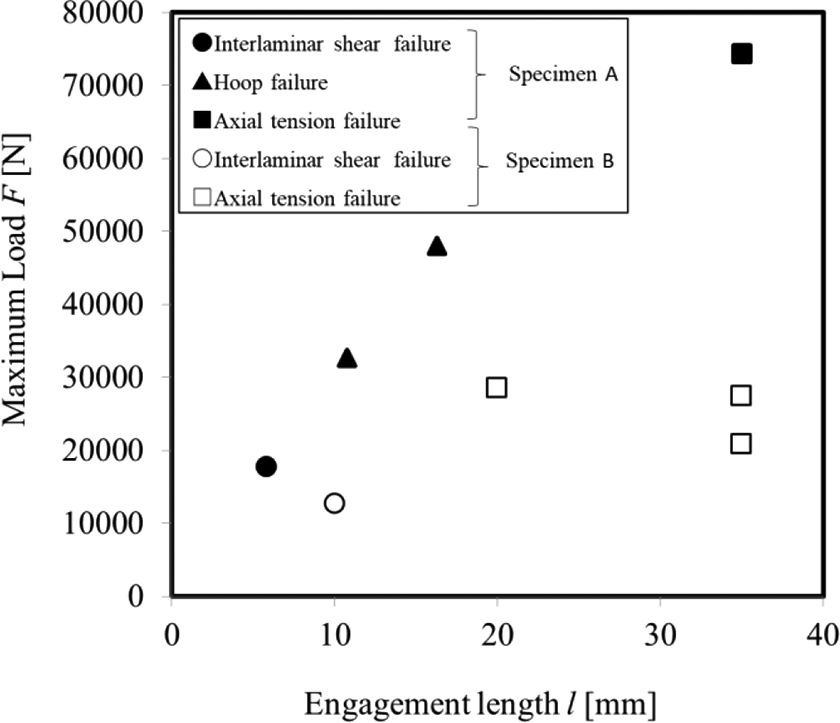
Relation between engagement length and maximum load.
Engagement length, failure loads, and failure modes.


Axial tension failure (specimen B, S/N 1, engagement length of 20 mm).
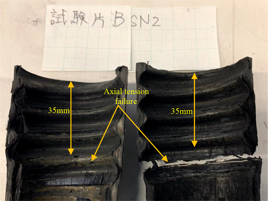
Axial tension failure (specimen B, S/N 2, engagement length of 35 mm).
Similarly, S/N 7 of specimen A also experienced an axial tension failure (Figure 8).
Axial tension failure (specimen A, S/N 7).
The reason is that a sufficient engagement length prevents failure on the threads; thus, the failure would occur at the end of the thread.
On the other hand, S/N 4 and S/N 6 of specimen A (engagement lengths of 16 and 11 mm) failed in hoop failure mode, as shown in Figures 9 and 10. The reason is that a short engagement length leads to a large axial displacement between the internal and external threads, which changes the contact angle of the threads and develops a large radial force.

Hoop failure (specimen A, S/N 6).

Hoop failure (specimen A, S/N 4, engagement length of 16 mm).
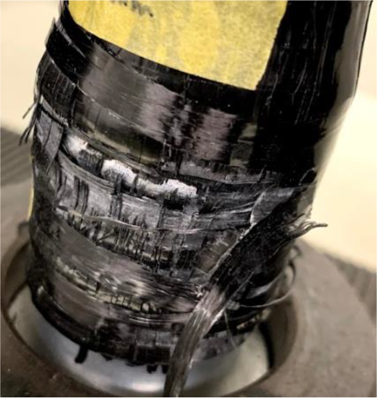
S/N 5 of specimen A and S/N 4 of specimen B (engagement lengths of 6 and 10 mm) failed in interlaminar failure mode. A typical interlaminar failure mode is shown in Figure 11.

Interlaminar shear failure (specimen B, S/N 4, engagement length of 10 mm).
The load-crosshead displacement curves of specimens A and B are shown in Figures 12 and 13. S/N 6 and S/N 7 of specimen A and S/N 2 and S/N 4 of specimen B went through local peak loads before reaching the maximum load. Each local peak indicates a local failure or first ply failure. Note that the curve for S/N 5 of specimen A is nonlinear because of the changing contact angle between the internal and external threads.

Load-crosshead displacement curve of specimen A.

Load-crosshead displacement curve of specimen B.
Development of analytical model
An analytical model was developed to predict the stress and failure strength of the premolded internal threads on composite tubes. To obtain a closed-form solution, the discrete model shown in Figure 14 and the following assumptions were used. The external thread is very stiff; it can be assumed to be a rigid body. The internal thread is elastic and thus deformed axially and radially; however, the shapes of the rounded threads are not deformed. An initial gap δr0 exists between the internal and external threads, as shown in Figure 15. The helical shape of the threads is simplified to be axisymmetric, like a Japanese abacus. Friction on the contact point is ignored.
Based on the above assumptions, equations (1) to (15) were newly derived.

Discrete model of internal thread.

Initial and deformed configuration of internal and external threads.
The subscript i = 0, 1, 2,…, n denotes the number of threads from the root of the internal thread, while α
u,0, α
u,1, α
u,2,…, α
u,n
denote the initial undeformed contact angles and α
d,0, α
d,1, α
d,2,…, α
d,n
denote deformed contact angles. Referring Figure 15, the radial and axial displacement


The subscripts a and r denote axial and radial. Using assumption (5), the relation between the axial force f a,i and the radial force f r,i per unit circumference length (line load) of a thread is

Neglecting Poisson’s effect,


where t a,i is the tension load on the axial spring. The relation between t a,i and axial force f a,i is
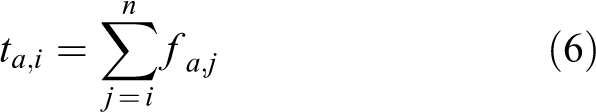
F a can be calculated using equations (1) to (6), where α u,0, α u,1, α u,2,…, α u,i . denote the initial contact angles. Substituting equation (1) into equation (4), f r,i becomes

Substituting equation (7) into equation (3) yields

The relation between α u,i , α d,i , α u,i + 1, α d,i + 1 and f a,i is obtained by substituting equation (2) into equation (5) and using equation (6)

Solving equation (9) gives α 0,i − α 1,i

α u,n − 1 − α d,n − 1 can be calculated using equation (10), by specifying α d,n , which is the deformed contact angle of the end of the internal thread, and then, α u,n − 2 − α d,n − 2,…, α u,0 − α d,0 can be calculated recursively. f a,i can be calculated by substituting equation (10) into equation (8), and F a is obtained as

The axial and radial stress σ a,i and σ r,i are calculated as follows


Neglecting Poisson’s effect, k a,i and k r,i for a ring of uniform thickness t, length p, and mean diameter d are written as follows

The failure load can be calculated using classical laminate theory.
A numerical example of load displacement for one thread engagement length is shown in Figure 16.

Load displacement curve of one thread engagement length.
Here, the effective thread diameter d was 37 mm, the radius of the thread r was 3 mm, and the initial contact angle α u,0 was 66.466 for both specimens A and B. The contact angle range was 0 ≤ α d,0 ≤ 66.466°, which corresponds to 0 ≤ δ a ≤ 5.5 mm. The radial line load increased monotonically and the maximum was at α d,0 = 66.466°, δ a = 5.50 mm. The maximum axial line load, however, was at δ a = 1.44 mm. The reason is that the axial line load f a,0 initially increases with increasing radial displacement, but then it decreases with increasing α d,0, as shown in equation (3). This result shows that the relation between the axial and radial line load is nonlinear, and thus, the axial and radial stress also change nonlinearly. Hence, the iterative calculation is required to predict the failure load by using classical laminate theory. 10
Discussion
The experimental and theoretical results are compared in Figures 17 and 18. The effective thread diameter d was 37 mm, the radius of the thread r was 3 mm, and the initial contact angle α u,0 was 66.466° for specimens A and B. The failure prediction using classical laminate theory and the Hashin criteria coincided with the maximum stress failure criterion in this case. Thermal residual stress during the 130°C cure and at room temperature, 21°C, were also considered to evaluate the Hashin criteria. Assuming that interlaminar shear failure is caused by shear failure on the matrix, the shear strength of the matrix can be calculated as

Comparison of test and analysis for specimen A.

Comparison of test and analysis for specimen B.

by using the von-Mises criterion. The interlaminar shear failure load of the thread calculated by equation (17), which is based on assuming the uniform interlaminar shear stress on fitting area πdl, is plotted in the figures as the redline

Generally, the prediction of classical laminate theory exceeds the experimental result. For specimen A (Figure 17), however, the prediction of the interlaminar failure calculation matched the experiment. This indicates the interlaminar failure induced the decreasing the laminate failure load. The prediction of classical laminate theory for specimen B (Figure 18) was almost constant and in good agreement with the experiment for engagement lengths of 20 and 35 mm. The prediction for specimen B with the engagement length of 10 mm (S/N 4) was much lower than the prediction of classical laminate theory because the specimen failed by interlaminar shear. The experimental load, however, was also lower than the prediction of the interlaminar failure calculation. A possible reason is the non-deformed shape of the thread of the analytical model and stress concentration on the thread.
The above results indicate that to predict the failure load, both the failure load of classical laminate theory and the interlaminar failure load should be calculated, and the lower value should be used as the predicted failure load of the internal thread.
Application
To demonstrate the developed premolded internal thread on a composite tube, a micro hybrid rocket engine with a CFRP motor case was developed (Figure 19). The hybrid rocket uses both solid-fuel-like plastics and liquid oxidizer and is nonexplosive and safe 11,12 ; it has thus attracted attention as new kind of low-cost rocket.

Motor case for micro hybrid rocket.
To evaluate the strength of the internal thread, the thickness of tube wall was designed on the safe side of internal pressure. In addition, a hoop layer was added to reinforce the parts with the thread. The design pressure was 10 MPa, which is twice the maximum combustion pressure of 5 MPa. The combustion test (as shown in Figure 20) was conducted without failure of the thread or motor case wall. The thrust and combustion chamber pressure (Figure 21) were as designed, and no damage was observed in a visual inspection of the internal thread after the combustion test (Figure 22). Hence, the development of the motor case with the premolded internal thread was a success.

Combustion test.

Thrust and pressure on combustion test.
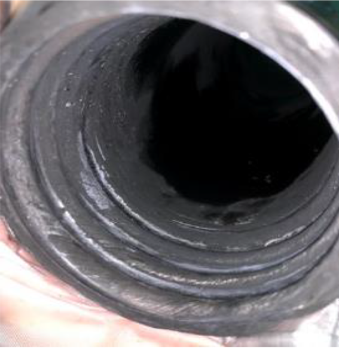
Internal thread after combustion test.
Conclusion
A premolded internal thread on a composite tube was developed. Two types of specimen were made and tested. An analytical model also was developed. The analytical model shows the nonlinear stress–displacement relation and was compared with the experimental results. The failure load was predicted using both classical laminate theory with the Hashin criteria and the interlaminar failure calculation. The developed premolded internal threads with new analytical model enable high-efficiency, innovative joint of composite tube which can be applied for struts and pressure vessels.
Footnotes
Declaration of conflicting interests
The author(s) declare no potential conflicts of interest with respect to the research, authorship, and/or publication of this article.
Funding
The author(s) disclosed receipt of the following financial support for the research, authorship, and/or publication of this article: This work was supported by the Takahashi Industrial and Economic Research Foundation.