
Abstract
For predicting the mechanical properties of discontinuous carbon fiber-reinforced thermoplastics (DCFRTP), it is essential to consider the microstructure, including the fiber orientation and the properties of the constituting materials. In the present study, a heterogeneous particle model, considering the microscopic factors, is constructed on the basis of the peridynamic (PD) theory to investigate the tensile properties of DCFRTP. Two kinds of randomly oriented DCFRTP, with different constituents and volume fractions of carbon fiber, are used for the verification of this numerical model. A comparison between the PD simulations and the experimental results shows a good agreement. The effect of the model size on the prediction is discussed.
Keywords
Introduction
Randomly oriented discontinuous carbon fiber-reinforced thermoplastics (DCFRTP) are regarded as potential substitutes for metallic materials applied in mass production of automotive parts because the randomly oriented discontinuous fiber systems generally show considerable complex-shaped molding capabilities without internal structural damage. The thermoplastic resins exhibit superior cycle molding time and good in-plant recyclability. Consequently, the combination of the thermoplastic polymers with the randomly oriented discontinuous carbon fibers has been gained considerable attention for high-speed processing and low-cost manufacturing of composite structures. 1,2 Relevant scholars have carried out a lot of research on the influencing factors of mechanical properties, including feature size, constituent properties, and molding process. 3 –12 Nishikawa et al. 13 found that the fiber length affects the nonlinearity of the stress–strain relationship of DCFRTP. Long but discontinuous fibers effectively increase the yield point of the composite. Wan and Takahashi 14 investigated the effect of compression molding conditions on the tensile and compressive properties of chopped carbon fiber ribbon-reinforced thermoplastics. It was found that the measured strengths exhibit high molding pressure sensitivity. Czél et al. 15,16 and Yu et al. 17 found that hybrid composites made of discontinuous fibers can provide a balanced suite of modulus, strength, and ductility, and allow avoiding catastrophic failure that is a key limitation of composites. Tapper et al. 18 and Longana et al. 19,20 studied the recycling performance of discontinuous carbon fiber composites and found that the samples do not show a decline in mechanical properties after recycling and remanufacturing. Matrix residues accumulated on the surface of recycled fibers help to improve the tensile strength and ultimate strain. The above studies have analyzed the effect of different influencing factors on the performance of DCFRTP, providing theoretical support for industrial applications of DCFRTP.
The heterogeneity of DCFRTP materials and the nonuniformity of the constituents lead to a highly complex internal structure. In addition to the influencing factors analyzed by the above researchers, the correlation between internal structures and material properties should be studied. 21 The randomly oriented strands in DCFRTP induce the in-plane isotropic mechanical property as well as the multiscale structure and high heterogeneity, which make the mechanical analysis facing more challenges, especially for the numerical analysis.
The previous numerical analysis of composites damage is conducted through finite-element model (FEM) and meshfree methods. An interelement separation model was proposed to model cracks along with element interfaces in the mesh. 22 Another method to model cracks is an intraelement separation model, which introduced crack segments in finite elements. 23 The extended finite-element method was developed to model crack in composites based on the “local” partition of unity. 24 In addition to FEM, the meshfree method was proposed to model the initiation and propagation of damage, such as cracking particle model. 25 Sertse et al. 26 presented many micromechanical tools developed and codified for understanding and analyzing composite materials and structures, including commercially available software packages that offer micromechanical analyses as stand-alone tools or as part of an analysis chain. The previous modeling methods have shown certain limitations. 27 The mesoscale factors, including the random distribution of short fibers, fiber length, and interface characteristics, have important effects on the mechanical properties of DCFRTP, but these mesoscale factors are hardly represented in a homogenization method expressed in the simplified FEM. 28 On the other hand, the constitutive equation involved in the conventional finite-element method is the partial differential equation of displacement field, which requires the continuity of the displacement, because the partial derivatives with respect to the spatial coordinates are incomputable along the discontinuities. The spontaneous formation of discontinuities is difficult to be simulated by means of traditional solid mechanics. 29 These difficulties limit the application of conventional numerical methods to the problem of damage and destruction in DCFRTP. The development and verification of simulation methods with considerable accuracy and efficiency are urgently required for not only the applications but also theory establishments of DCFRTP. 30 –33
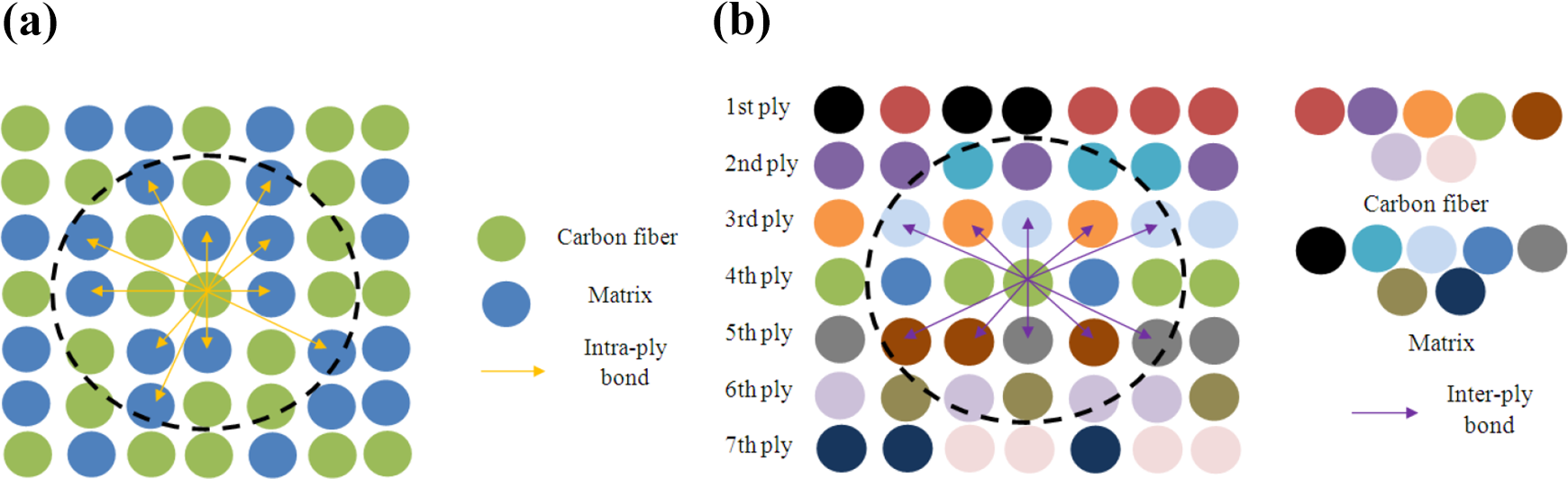
Recently, Silling 34 and Parks et al. 35 proposed a new continuum mechanics theory named peridynamic (PD) theory. In contrast to the local theory of classical continuum mechanics (in local regions, the constitutive relationship only considers the interaction between adjacent particles), as shown in Figure 1(a), the PD theory is a nonlocal continuum mechanics theory, as shown in Figure 1(b). The constitutive relationship is constructed by the internal force between any two particles in a certain range (a nonlocal area and the range size of the area in the PD model is called the horizon radius). The integral equations rather than differentiation equations are used to represent the constitutive relations, which can conveniently present the initiation and propagation of discontinuous displacements, such as damage and cracks. 35,36 PD theory has been initially applied to continuous fiber-reinforced composites. 37 –39 The consistency of the PD simulation and experimental results demonstrates that the method is capable of assessing the mechanical properties and realistically capturing the initiation and propagation of damage in continuous long fiber-reinforced composites, especially laminated composites. In addition, the horizon size in the PD model can be used to characterize the characteristic size of the material. Butt et al. 40 investigated the relationship between the size of PD horizon and the characteristic size of the heterogeneities through the comparison between the experimental results and the PD predictions about two kinds of sandstones. He proposed to associate nonlocality horizon with a characteristic length of material microstructure. The breakage of the bond between particles can simulate the initiation and propagation of damage through the PD motion equation, which involves the damage criteria. 41 Madenci et al. 42 developed a PD unit cell to predict the effective thermoelastic properties of microstructures in the presence of many defects and voids and complex heterogeneity. Cracks can be modeled by simply breaking the PD bonds between the material points.

Local theory of classical continuum mechanics and nonlocal continuum mechanics theory: (a) local model and (b) nonlocal model.
On the basis of PD theory, a new method for numerical analysis using heterogeneous particle models is proposed in this article. Two different types of particles (matrix particles and fiber particles) and the bond between particles are used to characterize the physical properties of the matrix phase and the reinforcement phase. The orientation of the bond between the fiber particles is used to characterize the orientation of the fibers in DCFRTP. This model can characterize the random orientation of fiber and the dispersion of mechanical properties caused by the sample size. Two kinds of DCFRTP are used for the verification of the method.
PD theory
PD theory is different from the classical continuum mechanics theory, which is a local model and employs the divergence of stress. Opposed to a weakly nonlocal theory or a strain gradient type nonlocal theory, PD theory is strongly nonlocal theory in which internal force density is represented as an integral of forces instead of an integral of stress in a weakly nonlocal theory. The primary kinematic field variable is displacement in PD model, while in classical continuum mechanics theory or weakly nonlocal theory, it is a strain or strain gradient. PD model has the advantages of addressing discontinuous problems.
For any material particle at the location x (x∈B), the equation of motion of PD theory is written as 35

where ρ is the mass density of particle
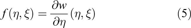
The constitutive relationship of the constituent material is specified through the function
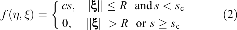

where
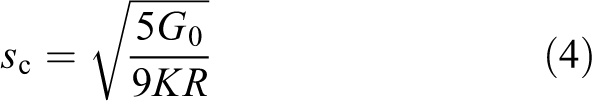
where G 0 is the critical energy release rate of material and K is the bulk modulus.
Numerical model of DCFRTP
Materials and specimens
In this article, two kinds of DCFRTP with long fiber length and random fiber orientation are used for the verification of the PD model. One is developed in Takahashi Lab in the University of Tokyo (noted as DCFRTP1) and the other is developed by Nishikawa in Kyoto University (noted as DCFRTP2). 13,14,43 DCFRTP1 is made of carbon fiber TR50 and PA6, which are provided by the Industrial Technology Center of Fukui Prefecture, Japan. DCFRTP2 is made of carbon fiber T700 and PA6, which are provided by the Ibaraki Industries Corporation, Japan. The constituents in DCFRTP1 and DCFRTP2 are listed in Table 1.
Properties of constituents in DCFRTP1 and DCFRTP2.

DCFRTP: discontinuous carbon fiber-reinforced thermoplastics.
PD model of DCFRTP
A heterogeneous particle model is proposed in this article. The particle with a certain volume, density, and type in the PD model can be used to present the different constituents in the heterogeneous material, as shown in Figure 2. Green particles which have the density of fiber denote fiber, and blue particles with the density of matrix denote matrix. All of the particles have the same volume. The ratio of fiber particle number to matrix particle number in the PD model presents the ratio of fiber volume to matrix volume in the specimen. The constitutive relationship of the constituent in the DCFRTP is specified through the particle interaction, which is regarded as a bond between two particles. Fiber particles and fiber bond are used to present the mechanical properties of reinforcement. Matrix particles and matrix bond are used to present the mechanical properties of matrix. The bond between fiber particle and matrix particle is used to present the interface properties. The relative position of two particles determines the orientation of the bond between these two particles, as shown in Figure 2. The orientation of bond denotes the orientation of constituent in DCFRTP. The random orientation distribution of carbon fiber can be simulated through the random orientation distribution of bonds between reinforcement particles, which are randomly selected as the reinforcement constituent.

Heterogeneous particles model.
The shape of the particles is cube. The cube’s edge is defined as the lattice constant a in the PD model and is determined by the computation efficiency. The DCFRTP1 and DCFRTP2 are in-plane oriented and the carbon fibers are randomly distributed in the in-plane direction. 13,43 According to the characteristic of carbon fiber orientation, DCFRTP1 and DCFRTP2 are simplified as a laminated structure in the PD model. Particles with an identical location in the thickness direction constitute one ply in the PD model. The thickness of DCFRTP is far less than the in-plane size. Limited by the computation capability, the lattice constant a is not small enough to present the actual thickness of one ply (44 μm), and the number of plies in the PD model is not equal to the actual number of plies in the specimen. The number of all particles in the PD model is determined by the actual size of the specimen, n = V/a 3, where V is the volume of the specimen.
The horizons of different constituents are identified, respectively, in the PD model to represent the mesostructure in DCFRTP, including the intraply horizon for the particles in the same ply and the interply horizon for the particles in the adjacent plies. One fiber particle has the fiber bonds with the other fiber particles (in the same ply) in its intraply horizon and has the interface bonds with the matrix particles (in the same ply) in its intraply horizon. It has interface bonds with particles (in the adjacent plies, including fiber and matrix) in the interply horizon. One matrix particle has three horizons for the matrix bonds with the other matrix particles in the same ply, the interface bonds with the fiber particles in the same ply, and the interface bonds with the particles in the adjacent plies. Therefore, each particle has three horizons, corresponding to three kinds of bonds, including one homogeneous bond and two interface bonds.
The micromodulus, c=mE, of different constituents is proposed in the heterogeneous PD model, where E is the elastic modulus and m is a parameter related to the model geometry. Consider a large homogeneous body under isotropic extension, that is, the stretch of bond s is constant for all relative position of two particles ξ and relative displacements η = sξ. A material is said to be microelastic if the pairwise force function is derivable from a scalar micropotential w
Because f = cs = cη/ξ, w = cη 2/2ξ = cs 2/2.
The micropotential w is the energy in a single bond and has dimensions of energy per unit volume squared. The energy per unit volume in the body at a given point (i.e. the local strain energy density) is therefore found from
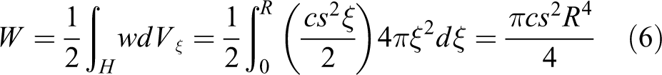
This is required to equal the strain energy density in the classical theory of elasticity for the same material and the same deformation, W = 9ks 2/2. It leads to the spring constant in the material model

The micromoduli of reinforcement, matrix, and interface were determined through the above equations, respectively.
For reinforcement

For matrix
For intraply interface
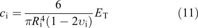
For interply interface

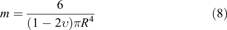
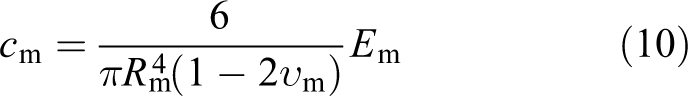
The subscripts r, m, i, and j denote reinforcement, matrix, intraply interface, and interply interface, respectively. To simplify the calculation, the transversal modulus of the unidirectional carbon fiber-reinforced tape, E T, is used to represent the micromodulus of the bond between the heterogeneous particles. At the same time, ν i = ν j = ν m. The intraply bond and the interply bond are shown in Figure 3.
Interface bond: (a) intraply interface bond and (b) interply interface bond.
The critical stretch of the homogeneous bond (reinforcement bond and matrix bond) is related to the critical elongation of constituent material (carbon fiber and PA6). The critical stretch of the intraply interface bond and interply interface bond is related to the critical energy release rate, as shown in equation (4). For the tensile load, the G IC of unidirectional carbon fiber-reinforced tape is used to represent the intraply interface bond, and the G IIC of the DCFRTP is used for the interply interface bond.
Results and discussion
Simulation of the random orientation of carbon fiber
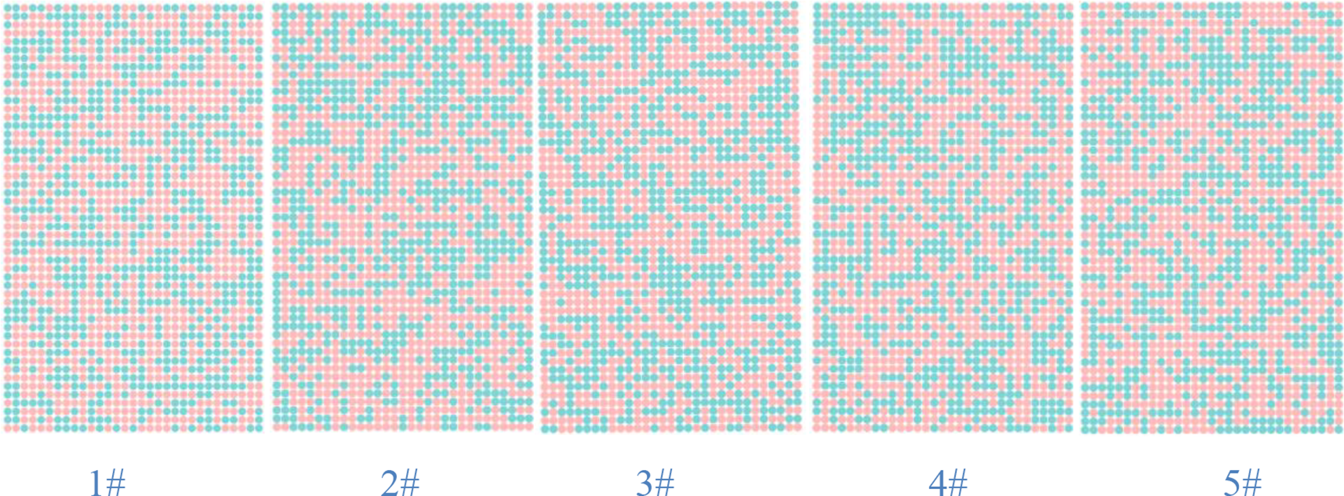
A PD model with a mini size (6 × 6 × 2 mm3) is firstly used for the verification of the numerical model. The lattice constant is 0.5 mm and the total number of particles is 845. The horizon radius of reinforcement particle and matrix particle in intraply is 3a. For the interply interface bonds, the horizon radius is a to ensure that the interaction is only available in the adjacent plies. The number of particles in the thickness direction is 5, namely, there are five plies in the PD model. To investigate the effect of random distribution of reinforcement on the mechanical properties of DCFRTP, five numerical models are used with different reinforcement distributions, as shown in Figure 4 (pink particles denote the fiber and blue and purple particles denote matrix). The simulated mechanical behavior of DCFRTP and the corresponding experimental results published by Wan 14 and Nishikawa et al. 13 are shown in Figures 5 and 6 and Table 2, respectively (the strength of two specimens of DCFRTP2 cannot be obtained due to the limit of the load cell, the limiting value 400 MPa is adopted as the strength). The simulated stress–strain curves agree well with the experimental results. At the primary stage of the tensile load, all PD models and experimental specimens exhibit the linear stress–strain relationship. While at the last stage of the tensile load, two experimental curves of DCFRTP1 are slightly concave-down at higher stresses. It is noticed that the simulated curves show a nonlinear stress–strain relationship near the peak stress. The slightly nonlinear mechanical behavior before fracture observed in the experiments can also be simulated by this PD model.

(a–d) PD models with different distributions (pink particles denote the fiber, blue and purple particles denote the matrix). PD: peridynamic.
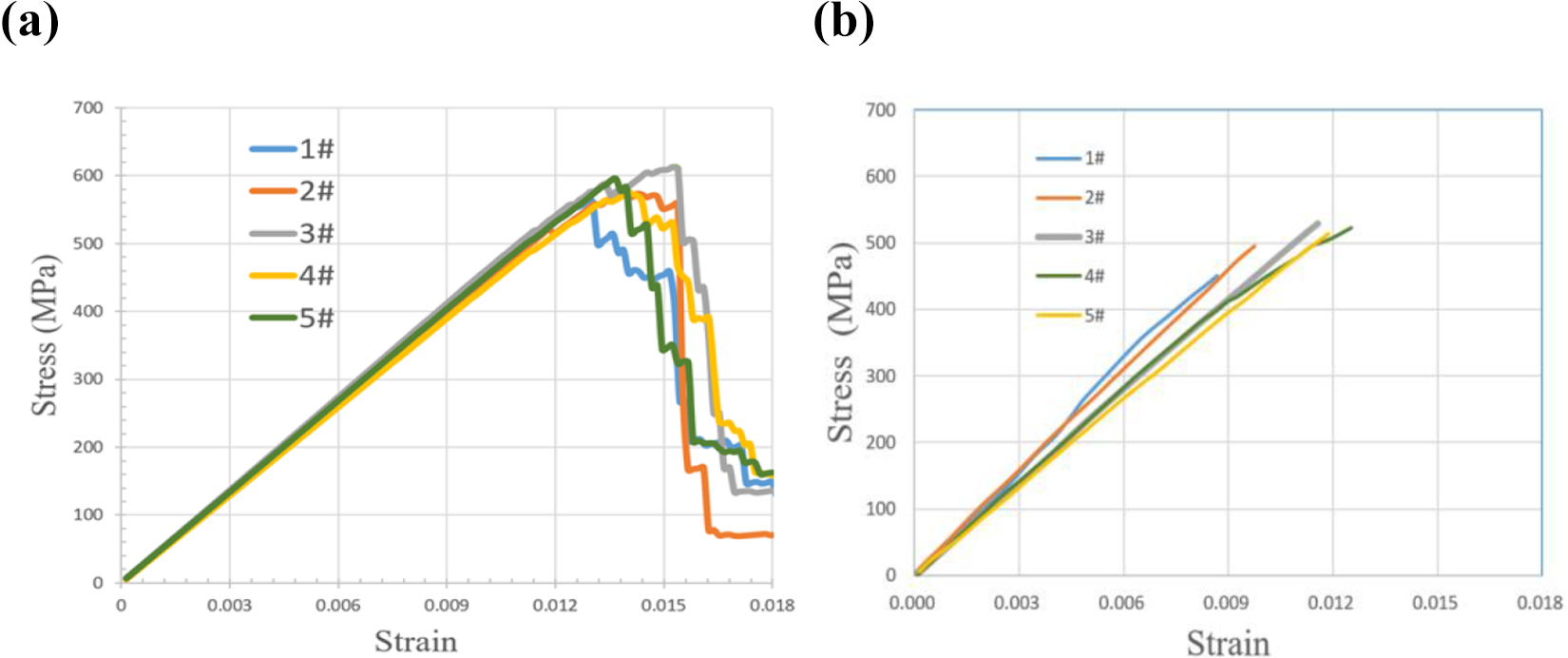
(a) Simulated mechanical behavior and (b) experimental mechanical behavior of DCFRTP1. DCFRTP: discontinuous carbon fiber-reinforced thermoplastics.

(a) Simulated mechanical behavior and (b) experimental mechanical behavior of DCFRTP2. DCFRTP: discontinuous carbon fiber-reinforced thermoplastics.
Simulated and experimental mechanical properties.
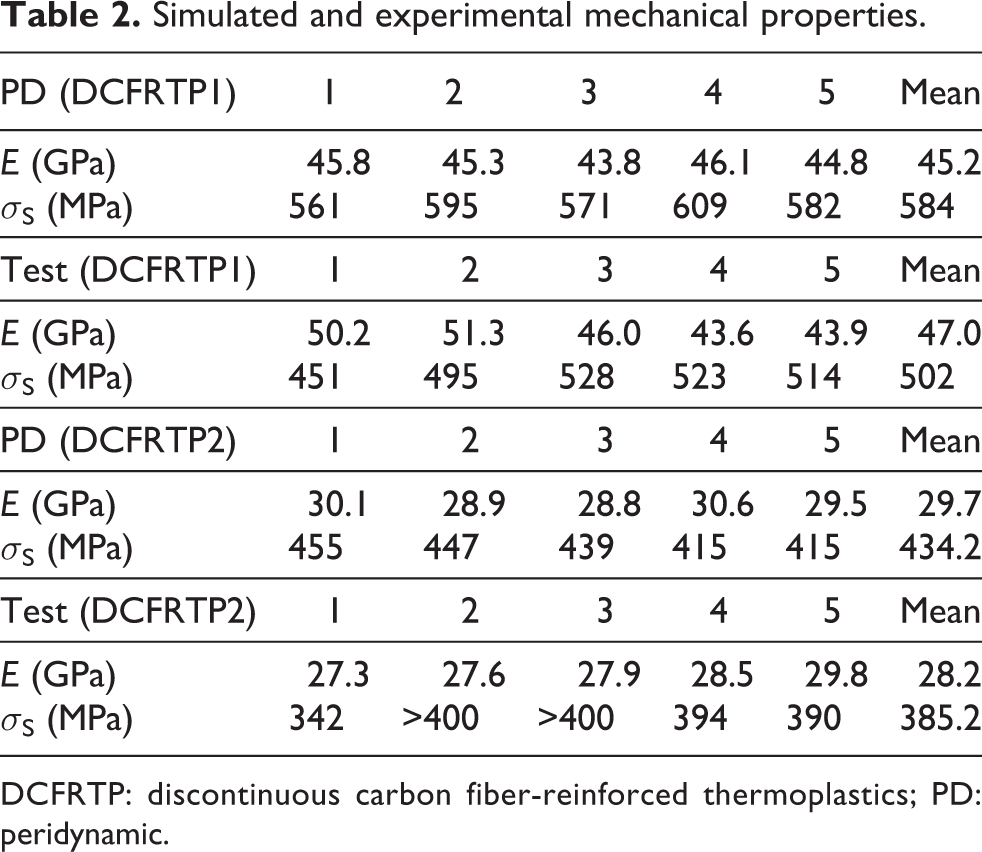
DCFRTP: discontinuous carbon fiber-reinforced thermoplastics; PD: peridynamic.
The elastic modulus and the fracture strength are listed in Table 2, and the comparison between experimental and simulated results is shown in Figure 7. The average elastic modulus of five DCFRTP1 specimens is 47.0 GPa, and the prediction one is 45.2 GPa. The average fracture strength of five DCFRTP1 specimens is 502 MPa, and the prediction one is 584 MPa. The average elastic modulus of five DCFRTP2 specimens is 28.2 GPa, and the prediction one is 29.7 GPa. The average fracture strength of five DCFRTP2 specimens is 385.2 MPa, and the prediction one is 434.2 MPa. The mechanical properties of DCFRTP are well predicted by this PD model. It is noticed that the scatter of the tensile mechanical properties of the specimens also exists in the PD model. The coefficient of variation (CV) of PD models is less than the one of experimental specimens for both the elastic modulus and strength. The scatter of the elastic modulus of the PD model is only induced by the random distribution of reinforcement, while for the experimental results, it is induced by the reinforcement random distribution and the uncontrolled variance in the process of the experiment.

Comparison of the tensile properties between simulation and experiment. (a) Elastic modulus, (b) strength, and (c) CV (E: elastic modulus; S: strength; PD: simulated results). CV: coefficient of variation.
Effect of the size of PD model on the prediction results
Two PD models with different sizes are used to investigate the effect of PD model size on the prediction of tensile properties. The characteristic parameters of the particle and bond are identical. The thickness of the two models is identical as well as the number of plies. The size of the in-plane varies to form the small model (6 × 6 × 2 mm3) and the large model (35 × 50 × 2 mm3). Five numerical models with different reinforcement distributions are also used for each size, as shown in Figure 8. The simulated stress–strain curves are shown in Figure 9. Compared with the simulated stress–strain curves of the small models shown in Figures 5 and 6, the large models show a linear mechanical behavior.
(a–d) PD models with different distributions (pink particles denote the fiber and green particles denote matrix). PD: peridynamic.

Simulated mechanical behavior of PD models: (a) DCFRTP1 and (b) DCFRTP2 (L denotes large size, other curves from small size). PD: peridynamic; DCFRTP: discontinuous carbon fiber-reinforced thermoplastics.
The simulated results of large PD models are listed in Table 3, and the comparison of the simulated tensile properties between small and large PD models is shown in Figure 10. It is found that both the small and large models well predict the tensile elastic modulus, and the prediction of the small model agrees better with the experimental result than the large model. The strength of the small model is higher than the corresponding experimental result, while the strength of the large model is closer to the experimental result. With the increase of the model size, the probability of the various kinds of the reinforcement distributions increases, including the kind of distribution, where the damage easily initiates and propagates. Therefore, the predicted tensile strength decreases with the increase of the model size. The strength prediction of the large model agrees better with the experimental result than the small one.
Simulated results of large PD model.

PD: peridynamic; DCFRTP: discontinuous carbon fiber-reinforced thermoplastics.
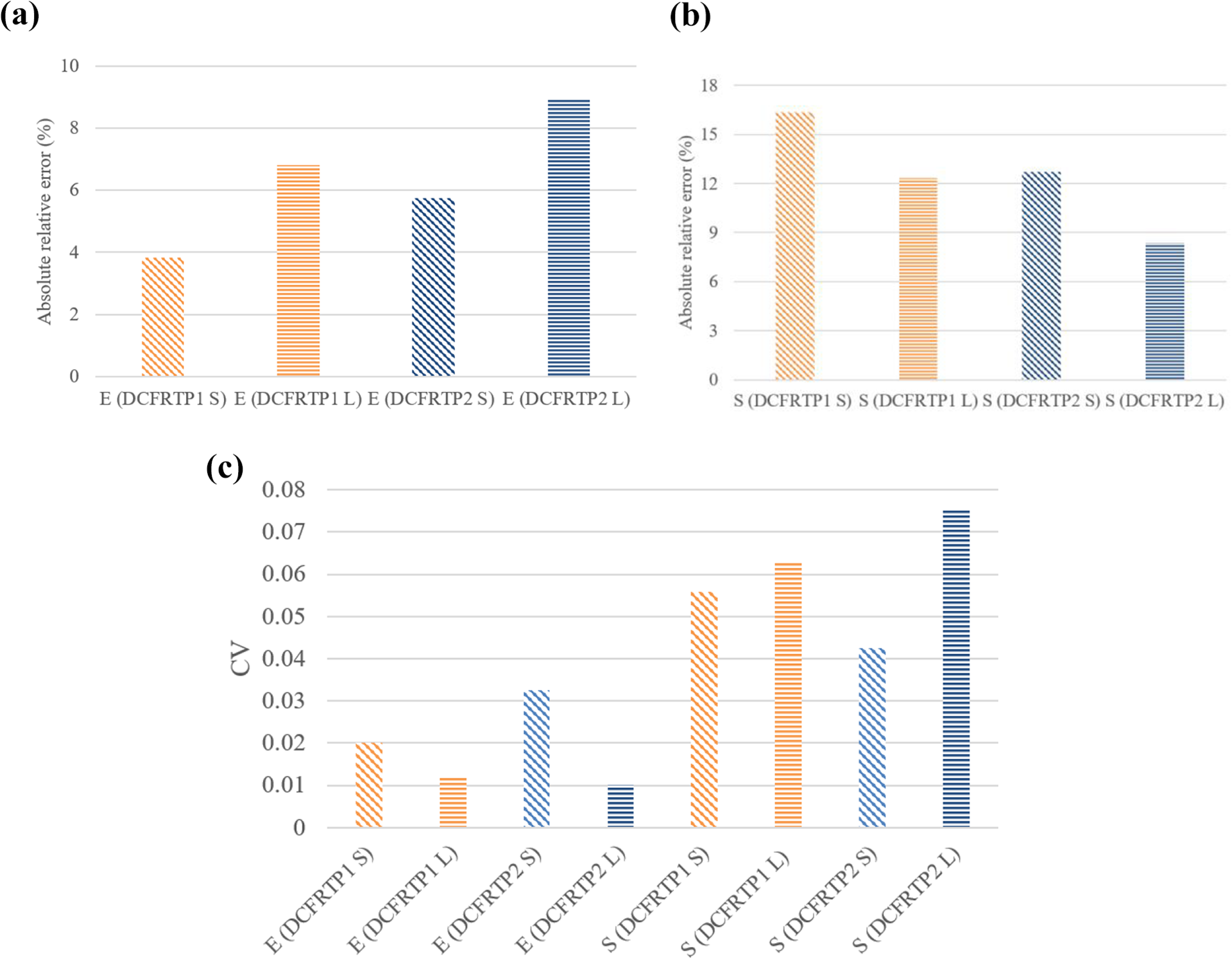
Comparison of the simulated tensile properties between small and large PD models. (a) Absolute value of relative error of elastic modulus, (b) absolute value of relative error of strength, and (c) CV of PD model (E: elastic modulus; S: strength; PD: simulated results; DCFRTP1/2S: small model; DCFRTP1/2L: large model). PD: peridynamic; DCFRTP: discontinuous carbon fiber-reinforced thermoplastics; CV: coefficient of varaition.
For the elastic modulus, the CV of the large model is less than the one of the small model. With the increase of the PD model size, the number of particles increases as well as the uniformity of the distribution of fiber particles. Therefore, the CV of the elastic modulus induced by the random distribution of reinforcement decreases.
The CV of the predicted tensile strength is influenced by the size of PD model. The large model shows more scatter of the predicted results than the small model. For the small model, the tensile crack propagates in a narrow zone, which is limited by the size of the model. For the large model, the tensile crack propagates in different paths with different reinforcement distributions. The initiation and propagation of the crack are more random in the large model than in the small model, which leads to more scatter of the predicted strength in the large model.
For the prediction of the mechanical properties of DCFRTP, small model should be introduced to simulate the elastic modulus with less calculation time. The tensile strength should be predicted by the large PD model of which the size is close to the actual size of the experimental specimen.
Verification of model for other composites material and structure
The heterogeneous particle model is verified against the predictions presented in two references. 26,42 A complex triply periodic short-fiber microstructure was represented by Sertse et al. 26 In this microstructure, the fibers are randomly oriented by rotations in each of the coordinate directions. The material properties of the fiber and matrix are listed in Table 4. The volume fraction of the fiber is 7.857%. The heterogeneous particle model for this microstructure is shown in Figure 11. There are 11 × 11 × 11, that is, 1331 particles in this model. One hundred and five particles are randomly selected as the reinforcement and the others are set as matrix. The prediction of this model agrees well with the simulated results from other numerical methods, as given in Table 5.
Constituent properties.

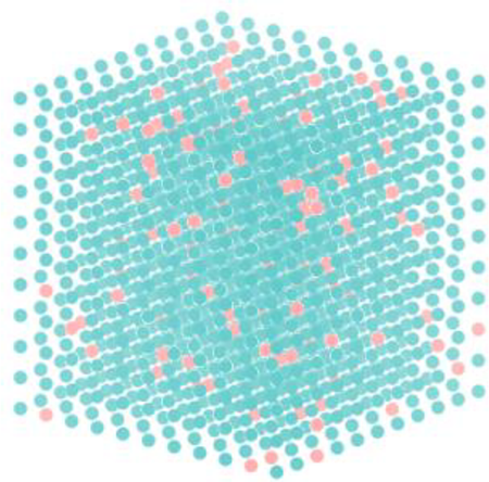
Heterogeneous particle model for the microstructure. 26
Comparison between the prediction of PD model and other predictions. 26
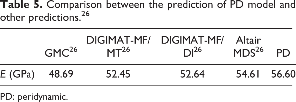
PD: peridynamic.
A microstructure of unidirectional fiber composites made of boron–aluminum constituents is presented by Madenci et al. 42 The cell dimensions L, W, and H are equal to unity. The material properties of the fiber and matrix are listed in Table 4. The volume fraction of the boron fiber is 47%, which corresponds to a fiber radius of r = 0.387. The heterogeneous particle model for this microstructure is shown in Figure 12. As expected, the effective material property matrix of the unit cell is transversely isotropic. For this model, the longitudinal modulus is 156.16 GPa and the transversal modulus is 226.06 GPa. It agrees well with the prediction by Madenci et al. 42 (longitudinal modulus is 144.42 GPa and the transversal modulus is 215.05 GPa).
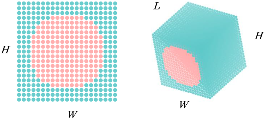
(a, b) Heterogeneous particles model for the microstructure. 42
Conclusion
A new numerical model is proposed for the mechanical analysis of the DCFRTP based on the PD theory. The random distribution of the reinforcement in DCFRTP is simulated by this PD model. Both the elastic modulus and the strength are predicted well through this PD model. The nonlinear mechanical behavior and the scatter of the mechanical properties of DCFRTP, which is induced by the random distribution of carbon fiber, are simulated by this PD model. The effect of the model size on the predictions is discussed. With the increase of model size, the predicted tensile strength and the scatter of tensile modulus decrease, and the scatter of the predicted tensile strength increases.
Footnotes
Declaration of conflicting interests
The author(s) declared no potential conflicts of interest with respect to the research, authorship, and/or publication of this article.
Funding
The author(s) disclosed receipt of the following financial support for the research, authorship, and/or publication of this article: This work was supported by the National Natural Science Foundation of China [51973105], China Postdoctoral Science Foundation funded project [2020M682117] and Scientific Research Fund of Liaocheng University [31805].