
Abstract
This article presents an experimental investigation to assess the influence of input process parameters of machinability of wire electrical discharge machining (WEDM) process for machining of triple-reinforced silicon carbide, graphite, and iron oxide hybrid aluminum (Al-6061) metal matrix composites. The composite work specimens, developed using stir casting process, have been processed through WEDM process by adopting a statistically controlled design of experimentation approach. Furthermore, analysis of variance and regression analysis have been performed to understand the influence of the input process parameters on material removal rate (MRR) and spark gap (SG) width. The statistical analysis highlighted the improvements in MRR and SG by 33.72% and −27.28%, respectively, upon adopting the suggested optimized range of input process parameters. Further, the morphology of the machined composite surfaces has also been studied using scanning electron microscopy and energy dispersive spectroscopy to report the phenomenon of formation of recast layer.
Introduction
The ever growing demand of materials designed to exhibit exceptional properties imperatively needed for numerous industrial applications has posed strenuous challenge to the researchers. Having witnessed a limited potential being exhibited by conventional materials, the metal matrix composites (MMCs) have become subject of key interest for practicing engineers owing to their tailor-made material properties combinations especially desired to cope up the necessitates of aviation, automotive, and defense industries. 1,2 Notably, particulate-reinforced MMCs offer high strength/weight ratio, high stiffness, and good wear resistance over monolithic materials, therefore offer potential commercial prospectus. 3,4 Recently, the hybrid MMC materials proved to be more attractive properties and these materials are fabricated by embedding matrix phase with two or more reinforcements to improve engineering properties. 5 The unique properties of hybrid aluminum (Al) matrix composites are intended for a wide range of applications, such as aircraft and fighter plane components, drive shafts, brake rotor, airframe structure, and automobile components (such as piston, cylinder liner, engine block, turbocharger, supercharger, valve gears, brackets, etc.). These materials can be fabricated by different methods, including liquid-metallurgy methods, solid-state consolidation technique, and deposition of matrix from a vapor or semisolid phase. 3 In particular, the liquid-metallurgy approach is highly attractive for fabricating composites, wherein the liquid stir casting process has been recognized as one of the most viable and economic methods to fabricate particulate-reinforced composites. 4,6,7 Reportedly, the manufacturing industries are keen in investing for improving the methods to produce economical and precise mechanical components which otherwise may not be possible without considering the importance of machining processes. Manufacturing industries primarily rely on turning, drilling, and milling and other conventional machining methods for processing of the materials. Owing to the presence of reinforcements such as aluminum oxide (Al2O3), silicon carbide (SiC), and boron carbide, which are hard and sometimes even harder than tool material and highly abrasive, the processing of MMCs proves to be an uphill task since their existence. The major challenge arises in machining of MMCs, when de-bonded particles come between tool edge and work surface; it subsequently causes rapid tool wear, poor surface integrity, and burr formation. 8–10 The ploughed particles through the matrix form grooves and scratches. 11 Further, matrix tearing may take place during surface generation when the cutting tool faces agglomerated reinforcements. Increase in size of ceramic particle also enhances tool wear 12,13 which further reduces the surface finish of machined surface. This observation was further substantiated by Kannan and Kishawy 13 while machining the composites with 10 vol% alumina particles in an Al-6061 matrix wherein increased size was accounted for significant damage to tool and machined surfaces. Many authors recommended the use of polycrystalline diamond (PCD) tools to reduce the deterioration of the machined surface as these tools are less prone to wear among available tool materials, but high cost associated with them limits their use. 14–16 PCD tools exhibits chipping damage due to its sharp cutting edge by impact of loosened ceramic particles from the spinning MMC work piece. 13,16 Alternatively, MMCs can be machined using nontraditional machining approaches, such as laser cutting, water jet machining, and electrical discharge machining, without considering the physical properties of MMCs. The wire electrical discharge machining (WEDM) has been proved as an efficient machining process to machine these materials achieving reasonably good precision and economy. 17,18
Yue and Dai 19 adopted a strategy by varying one factor at time to explore machining behavior of Al/Al2O3 MMCs. They found that the sizes of particles had significant influence in determining the banding and surface roughness (SR). The fiber-reinforced composites were found to be machined to a better surface finish than particle-reinforced MMC. The authors also reported that machined surface of MMC was inferior to the unreinforced Al matrix under fine cutting conditions. Gatto and Iuliano 20 carried out an experimental investigation to determine WEDM machinability of Al/SiC composites and didn’t observe the presence of SiC particulates in the recast layer of machined work material. Rozenek et al. 21 studied the WEDM of MMCs and highlighted that the cutting speed for machining a reinforced metallic composite should be considerably lower than the pure matrix. Yan et al. 22 performed experiments to machine alumina-reinforced Al matrix using a computerized WEDM process. It has been found that the high wire speed, low wire tension, and high flushing rate are some of the vital process parameters to prevent the wire breakage. Manna and Bhattacharyya optimized the WEDM parameters in response to material removal rate (MRR) and SR and proposed mathematical relations to establish improved machinability criterion. 9 Further, Patil and Brahmankar 23 investigated that during WEDM of Al matrix composites, the disintegration of alumina particles from the machined surface has deteriorated the desired surface finish of machined workpiece. It has been reported that an increase in the percentage of the reinforcement can render narrower kerf profile on machined samples. 24 Apart from this, other defects such as wire breakage, black spots, and cracks can also prominently deteriorate the machined surface textures during WEDM processing. 25 The vigilant examination of spark eroded surface shown that the poorest surface structure occupied with large number of cavities and enlarged craters is predominantly due to the higher pulse-on-time and lesser volume of nano-SiC in composites. 26 The close examination of cross section of the wire electrode clearly indicated the influence of reinforcement size on degradation of brass wire electrode. A severe degradation has been noticed at the curved edge at the front and straight edge side which participates in cutting of MMCs. 27
Besides other control parameters of interest, the type of ceramic reinforcements is also an important attribute influencing performance measure. Satishkumar et al.
28
performed the L9 (orthogonal array (OA))-based machining experiments on three variants of MMC material reinforced with particulates of SiC in vol. fraction of 5%, 10%, and 15%, respectively, and examined the WEDM characteristics of the process. The analysis of variance (ANOVA) method was employed to draw a conclusion from the results of experiments. The researchers verified through experiments that SiC% was crucial factor to determine the SR of machined samples. It has been reported further that ceramic particles shield the matrix materials from intense heat of discharge thus influencing erosion rate, surface characteristics, and taper of kerf.
29
It has been found that the recent studies are oriented toward the investigation of the machinability prospects of differently reinforced hybrid MMCs.
30–33
Despite the availability of the broad range of research activities in the themed research, the two existing research gaps are as follows: There are very limited studies available on the optimization of the differently hybrid metal composites. The phenomenon of the formation of recast layer during WEDM of hybrid MMCs is not addressed.
On the basis of the literature review, the authors have been persuaded to conduct the experimental investigation to suggest the optimal machining parameters for effective machining of stir casted hybrid Al-MMC subjected to attain maximum MRR and minimum spark gap (SG) for considered range of control parameters. The current research article broadly presents a comprehensive procedure to figure out optimal settings of machining parameters based upon the design of experimentation approach. Besides indicating the outcome of signal/noise (S/N) ratio analysis and ANOVA, the research article indeed purposes the mathematical models which are developed to correlate the machining response characteristics with machining control parameters. The machined surface textures have been analyzed through scanning electron microscopy (SEM) and energy dispersive spectroscopy (EDS) analysis to further explain the phenomenon of formation of recast layer during machining.
Fabrication of hybrid Al-MMC
The fabrication of differently reinforced hybrid aluminum (AA6061) matrix composites has been prepared through liquid stir casting process. The particulate reinforcements, such as SiC, graphite (Gr), and iron oxide (Fe2O3), have been selected in percentage weight proportions of 10%, 3%, and 3%, respectively. Three furnaces of capacity 1250°C, 1050°C, and 550°C were simultaneously used for melting of Al-6061 alloy, preheating of SiC, Gr, and Fe2O3 reinforcements, and baking of clay coated metal mold cavity, respectively, during casting of hybrid composites. The resistance heating furnace equipped with temperature regulator/indicator was used for stir casting of hybrid MMC samples. The melting was performed in a Gr crucible. A Gr stirrer and a three-blade impeller were mounted at 120° × 45° to stir the melt mixture and uniformly mix the reinforcements. An electric motor was used to control the stirring speed and to create a vortex flow. For sound castings, effective stirring of the molten mixture is highly important to achieve uniform mixing of constituents. The stir casted samples were tested for their mechanical properties, such as hardness and tensile strength, refer Table 1. Further, Figure 1(a) to (c) shows the SEM and EDS results of differently reinforced hybrid composite (polished sample). The SEM image has been captured at an accelerating voltage and magnification of 20 kV and 1000×, respectively. It can be seen in Figure 1 that the overall surface area on selected region has identified the presence of Al as major element along with Si, Gr (allotrope of C), and Fe (allotrope of Fe2O3). The mechanical properties of the cast samples were tested as per standard procedure explained elsewhere. 34
Properties of Al-matrix (AA 6061) and hybrid Al-MMC.

Al: aluminum; MMC: metal matrix composite; BHN: Brinell hardness number.

Scanning electron microscopic image and EDS analysis of stir casted hybrid Al-MMC. EDS: energy dispersive spectroscopy; Al: aluminum; MMC: metal matrix composite.
WEDM of hybrid Al-MMC
Planning for experimentation
Electronica Sprintcut-734 WEDM (Electronica India Limited) was used for machining of work material. Performance measures, namely, MRR and SR heights, were recorded while performing WEDM machining experiments. The work material, tool electrode, and the other machining conditions were considered for experiments as follows: Work-piece: Hybrid Al-MMC (anode). Thickness: 12 mm. Programmed size of the workpiece: 5 × 5 × 12 mm3. Tool: Brass wire electrode of 250 µm (cathode). Dielectric fluid: deionized water (temperature: 22–25°C). Flushing pressure of deionized water: 14.5 kg/cm2. Specific resistance of deionized water: 1–3 mA. Peak voltage (VP): 100 V.
A set of preliminary experiments were carried out to set the level of the various parameters of WEDM. Based on the acquired results from preliminary experiments six parameters, such as: pulse peak current (I p), pulse-on-time (T on), pulse-off-time (T off), wire feed rate (W F), wire tension (W T), and SG-set voltage (SV) are selected. The levels of the identified input process parameters are given in Table 2.
WEDM parameters and their levels considered for experiments.

WEDM: wire electrical discharge machining; I p: pulse peak current; T on: pulse-on-time; T off: pulse-off-time; W F: wire feed rate; W T: wire tension; SV: set voltage.
To produce the desired profile on the workpiece, a minimum SG is desired to ensure precise cut in WEDM process especially components demanding close tolerances. It is evident that when the wire electrode travels without any offset along the programmed path, the actual size of the machined workpiece becomes undersize. Therefore, it is essential to compute the wire offset to make the correction in the path profile of wire in the CNC program. 35 So, equation (1) has been used to determine the SG width (W g; µm), as follows

where b is the width of cut in millimeters and d is the diameter of the brass electrode (250 µm). The width of slot formed between outer surface of cut work piece and inner surface of remainder composite after machining experiment was measured at five locations using TESAMASTER micrometer (EuroPac Precision).
The MRR (mm3/min) for each set of experiment has been calculated using equation (2) 17

The mean cutting speed (C m; mm/min) was recorded from the display screen of the Sprintcut WEDM machine during experiment. The height of workpiece “h” and width of cut “b” were also measured using micrometer.
Design of experiments
The scrutiny of appropriate OA used in this experimentation was determined through calculation of the total degrees of freedom (DoFs). The DoF is based on the levels of each individual control parameters and considered interaction between design parameters. Based on the calculated DoF, the L27(313) OA was selected which enabled to conduct the 27 machining experiments. The optimal level of a process parameter is the level which results in the highest value of S/N ratio transformation. In the Taguchi method S/N ratio (dB), the term “signal” stands for the undesirable value (SD) for the output characteristic. The S/N ratio defined in mathematical aspect as the higher-the-better (i.e. maximize, example: MRR) is described

while for lower-the-better (i.e. minimize, example: SG)

where S/N ratio (dB) denoted by η computed from experimentally observed values; yi is termed as the experimentally acquired response of the ith machining experiment, while n is the number of repetitions of each machining experiment. 12 Utilized the acquired results, calculated the S/N ratio and drawn S/N ratio graphs for optimization of WEDM parameters for different response characteristics.
Results and discussion
Table 3 represents the raw data and S/N ratio obtained for MRR and SG. As per the Taguchi method, the significant parameters can be identified through ANOVA. The results developed through mathematical models bear the relationship between WEDM control and response parameters. Figure 2 shows the S/N ratio (dB) graphs for MRR indicating the influence of the different levels of the control parameters. Notably, the optimal level of machining control parameter is identified to be peak S/N ratio plot. Based on Figure 2, the optimal condition that can yield maximized MRR is identified to be A2B3C1D3E2F3 (i.e. parameter A2 (level 2, S/N = 19.39), parameter B3 (level 3, S/N = 19.52), parameter C1 (level 1, S/N = 19.57), parameter D3 (level 3, S/N = 18.58), parameter E2 (level 2, S/N = 18.62), and parameter F3 (level 3, S/N = 18.67)). Further, Table 4 represents the ANOVA and F-test values with contribution of each WEDM parameters for MRR. The significance of each machining parameter can be determined using ANOVA. 36,37 Table 4 also represents the most significant (marked by the superscript letter b) and significant (marked by the superscript letter a) WEDM parameters for MRR concerning the machining of hybrid Al-MMC.
Control log of experimentation.

I p: pulse peak current; T on: pulse-on-time; T off: pulse-off-time; W F: wire feed rate; W T: wire tension; SV: set voltage; MRR: material removal rate; SG: spark gap.
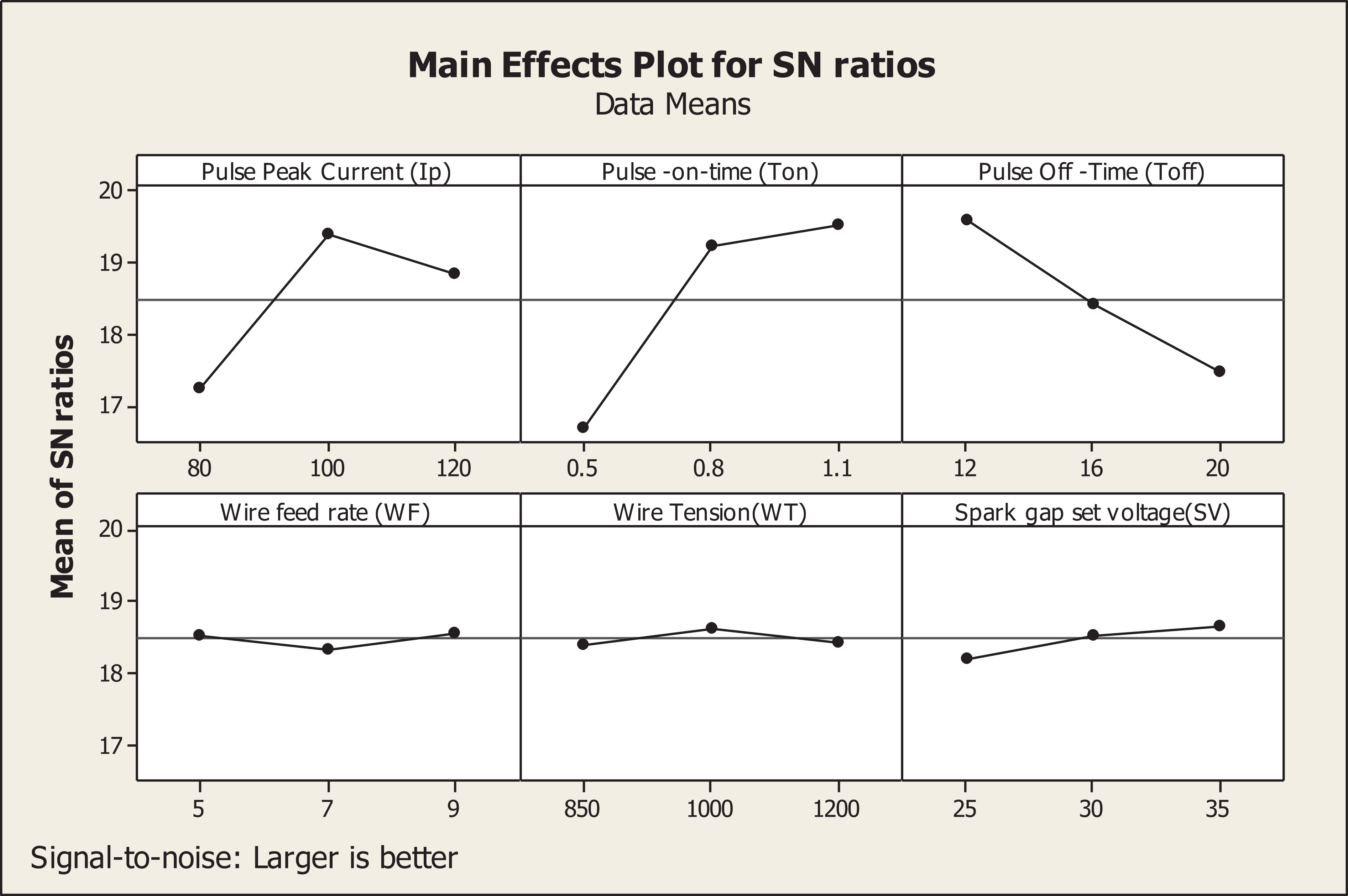
S/N ratio plot for MRR. S/N: signal/noise; MRR: material removal rate.
ANOVA for MRR.

ANOVA: analysis of variance; MRR: material removal rate; I p: pulse peak current; T on: pulse-on-time; T off: pulse-off-time; W F: wire feed rate; W T: wire tension; SV: set voltage.
From Table 4, it can clearly be figured out that pulse-on-time had most significant effect on MRR with contribution of 46.50%. Further, the pulse-peak current and the pulse-off-time have been noticed to be statistically significant with contribution of 23.30% and 22.53%, respectively. Along with these, the wire feed rate can also be not ignored as it has F-test value of 3.45, with a contribution of about 2.03% in MRR.
The setting of current and pulse duration affects the spark intensity and hence the MRR. 38 Figure 2 illustrates that the MRR escalates as pulse peak current amplifies from 80 A to 100 A. However, a drop in MRR has been witnessed when pulse peak current amplifies from 100 A to 120 A. This discrete trend emerged owing to stochastic nature of the WEDM process. The material removal mechanisms, such as sparking, melting, vaporizing and removal of material by impulsive force, have been activated during rapid and repetitive sparking in WEDM. It became more effective when machining was carried out at moderate level of peak current. Further, at high level of peak current, MRR was dropped slightly on account of contamination of gap caused by increased number of debris and dislodged ceramic reinforcements. Machining experiments at longer spark duration, such as more expansion in plasma channel, enhance melting of material per spark in the gap. Hence, amplification of pulse-on-time results in augmented MRR. Figure 2 also depicts the influence of pulse-off-time upon MRR. Since no sparking takes place during pulse-off-time interval, the MRR was expected to drop. A sharp reduction in MRR was noticed at peak pulse-off-time owing to reduced frequency of sparks for a specific period of machining cycle. The S/N ratio plot for MRR further demonstrates that the MRR is highest at the moderate setting of wire tension. Machining at different levels of wire feed rate as well as SG-SV caused a marginal deviation in MRR.
In case of SG, refer Figure 3 for S/N ratio plot, the parametric combination for obtaining minimum SG has been observed as A1B1C3D1E1F1. It means that the best parametric level for parameter A: level 1 and S/N 33.99 dB, B: level 1 and S/N 33.94 dB, C: level 3 and S/N 33.42 dB, D: level 1 and S/N 33.4 dB, E: level 1 and S/N 33.21 dB, and F: level 1 and S/N 33.16 dB. The ANOVA results for the SG are displayed in Table 5 and depict the influence of the input control parameters. It has been found that the most significant factors for SG are pulse peak current (53.02%) and pulse-on-time (50.79%). Likewise, pulse-off-time and wire feed rate also influence the SG, significantly.
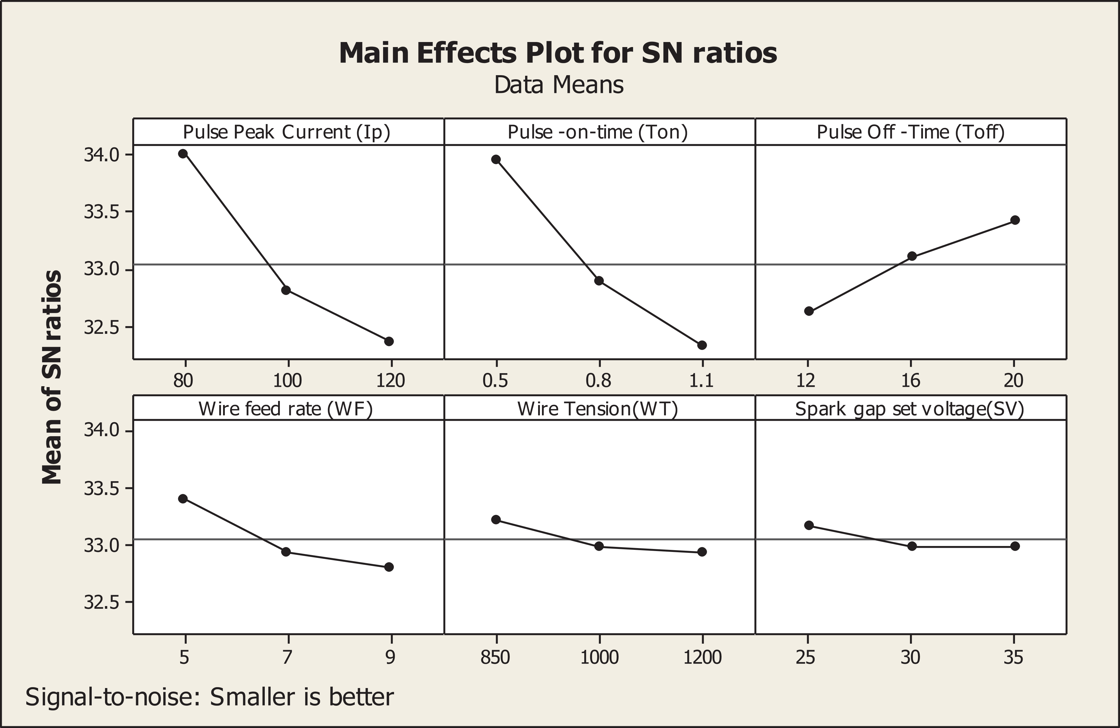
S/N ratios plot for SG. S/N: signal/noise; SG: spark gap.
ANOVA for SG.

ANOVA: analysis of variance; SG: spark gap; I p: pulse peak current; T on: pulse-on-time; T off: pulse-off-time; W F: wire feed rate; W T: wire tension; SV: set voltage.
S/N ratio graph illustrates that SG exhibited a linear trend with pulse peak current and pulse-on-time. It further indicates that high level setting of these parameters could increase the SG width and hence promotes geometrical inaccuracy. Further, the stability of the SG width is adversely affected at high wire feed rate because of vibration and collision of wire with ceramic particles presence in the hybrid MMC workpiece. 25
Estimation of predicted MRR and SG
Prior to performing confirmation experiments to verify the optimal conditions of input process parameters, confidence interval (CI) of predicted responses has been computed. The CIs for mean optimum values of MRR and SG were established using following mathematical models 39
CI for MRR is as follows

where

where,


Further, the predicted mean MRR at optimum conditions (such as A2B3C1D3E2F3) has been calculated using equation (7)

where T MRR is 8.576 mm3/min (overall average of MRR corresponding to all the 81 set of experimentations). The calculated values of average MRR at optimum levels are A2 = 9.47, B3 = 9.471, C1 = 9.642, D3 = 8.524, E2 = 8.742, and F3 = 8.745 (refer Table 6). After substituting these values in equation (7), the mean optimum value of MRR is predicted as 11.714 mm3/min.
The predicted optimal MRR at 95% confidence level should obey the condition given by equation (8)


It has been found that the predicted value for MRR (11.714 mm3/min) satisfies equation (8) at 95% confidence level. Similarly, the CI for predicted mean value of SG was computed following the same procedure. The input variables required in equations (5) and (6) are identified as:

Using Table 6, the mean SG at optimal condition is computed using equations (7) and (8)


Means at three levels of control parameters for MRR and SG.

MRR: material removal rate; SG: spark gap; I p: pulse peak current; T on: pulse-on-time; T off: pulse-off-time; W F: wire feed rate; W T: wire tension; SV: set voltage.
Development of mathematical relations
To determine the correlations between a machining parameters and response characteristics, the multiple linear regressions were used and developed the mathematical relation for each of the responses. The regression function was evaluated to confirm the validity of the established mathematical models. Applying multiple linear regression analysis using MINITAB 17 software, the mathematical relations were developed to predict the responses, namely, MRR and SG. These developed mathematical relations can be directly utilized to predict the response values in advance within the given range of control parameters.
Mathematical relation for MRR and SG as evolved after machining are
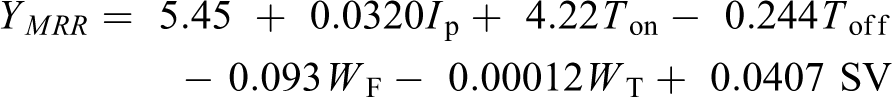
where R 2 = 85.88%.

where R 2 = 90.7%.
Furthermore, the normality assumptions are satisfied, if projection of residuals plot projects along a straight line. 38 The residuals for MRR and SG (refer Figure 4) lie apparently close to a straight line indicating that errors are distributed normally, and predicted values bear good agreement with experimental results.

Normal probability plot for (a) MRR and (b) SG. MRR: material removal rate; SG: spark gap.
The predicted response results are validated by performing confirmation experiments restricting to optimal levels of machining variables. The results obtained during confirmation experiment are presented in Table 7. The measurements of confirmation tests (n = 3) for MRR and SG have been conducted with regard to the respective optimal conditions. The corresponding values have been observed as 11.4 mm3/min and 0.016 mm, respectively. Further, the mean observed values of MRR and SG falls within the determined CIs, for instance, 10.992 < MRRexp < 12.436 and 0.0147 < SGexp < 0.0171, respectively. Further, the predicted values are also very close to experimental results.
Results of confirmatory experiments.

MRR: material removal rate; SG: spark gap.
Examination of recast layer
Machined surface morphology plays a crucial role in improving the precision, reliability, and quality of the components. The cut surfaces produced by WEDM of the composites were sectioned in transverse direction for microstructure observations in machined areas. Figure 5(a) to (c) displays the workpiece machined microstructure image under the following machine settings: 120A—pulse peak current, 1.1 µs—pulse-on-time, 16 µs—pulse-off-time, 5 m/min—wire feed rate, 850 g—wire tension, and 35 V—SG voltage. At high setting of pulse peak current and pulse-on-time, it is generated enormous thermal energy during ionization phase. This raises up the local temperatures; eventually, the materials are melted and partially vaporized and flushed away by recirculating deionized water. Consequently, the tiny and large craters (Figure 5(a)) are also formed on the machining areas owing to the blasted out molten work by the discharge pressure. Grouping of individual tiny craters can be noticed, which probably are caused by raised up material temperatures. In turn do not permit sufficient time for dielectric cooling of an individual crater formed in due course before the next discharge occurs. 40 Subsequently, the surface moving away from spark zone attains the solidification temperature due to the presence of dielectric fluid and demonstrates the final surface structure (Figure 5). In addition to this, the material removal process also promotes the disintegration of the ceramic reinforcements to form large craters (Figure 5(a)). The increased pulse peak current and pulse-on-time exhibits a vital role in size of craters formed in the machining areas and other surface characteristics. Figure 5 depicts the formation of black patches besides the presence of formation of fine surface enveloped by tiny and shallow size craters. The black patches confirm the incidences of arcing occurred during machining owing to the presence of debris over the machined surface (Figure 5(b)).

Machined surface at high pulse energy (1.1 µs—pulse-on-time and 120A—pulse peak current).
EDS plotted in Figure 6(a) and (b) reveals the presence of oxygen. It is likely to increase with extended pulse-on-time. Oxygen is released owing to the disassociation of dielectric fluid (deionized water) at very high temperatures. Therefore, the porous surfaces have been spotted in the machined areas as can be noticed from Figure 6(a). Oxidation and decomposition process liberates a huge amount of gas due to more heat input by extended time intervals of discharges. This could cause more porous surfaces in the machined areas and therefore decreases the hardness and fracture toughness of the spark eroded surfaces. The EDS of the surface is also referred for elemental analysis which enables to determine the migration of electrode material to machined surface. EDS elemental maps in Figure 6(b) show that the machined work surface contains only elements of target material, namely, Al, carbon, oxygen, and magnesium, and Cu. The presence of element “Cu” indicates that partially melted wire electrode migrates on machined surface. The wire wear can increase the SR. The presence of Si in the machined surface was apparently noticed which confirm disassociation of some SiC particles at high temperatures. 27

EDS analysis confirming migration of electrode material into recast layer. EDS: energy dispersive spectroscopy.
The recast layer is formed by resolidification of the molten material which is not dispensed off by the flushing. This material is subjected to intense heating by the electrical discharges and rapid quenching by the dielectric fluid which can promote cracking and residual stresses. With higher energy release in each spark associated to an increased pulse energy, the amount of matrix material which is melted is higher results in a thicker recast layer as shown in Figure 7. The presence of ceramic particles in the work material and variation of spark energy has produced a nonuniformity in the recast layer. The recast layer is noticed to be fine grained and hard.

Recast layer formed on machined surface.
The residual stresses are another important consideration in understanding surface integrity of the machined surface. It is derived from material processing and machining history. The rapid metallurgical transformations and temperature gradient spikes in EDM process generate residual stresses in the recast layer. 41 These stresses sometimes exceed yield point of the target material and promote severe twining, slip, and cleavage subject to the type of crystal structure. 42 The residual stress significantly impacts the fatigue life of the machined components and also causes cracking or distortion in some cases, thereby leading to premature service failure. As mentioned earlier in this article, recast layer thickness grows to be thicker with increase in the pulse energy desired for high MRR, that is, rough cutting. Further, this growth in the average recast layer thickness induces more stress on the machined surface. Therefore, factors governing pulse energy, that is, pulse-on-time and peak current, are crucial for severity of induced residual stresses and crack formation. The absence of tearing cracks in softened machined surface by the local raised up temperature indicates that only compressive or moderate tensile residual stress is present in the recast layer. 43 Cracks are not clearly visible on the machined surface indicating that rapid dissipation of heat occurs from recast layer while machining takes place (Figure 5(a)). Yet, the finish machining is desired to achieve better surface quality as material settled to higher stress during rough machining gets removed. 44 In future, the multi-objective optimization must be performed to reduce energy consumption and attain sustainable machining goals. 45,46
Conclusions
The hybrid Al-MMCs samples were successfully fabricated using stir cast technique. The robust design of experiment technique has been applied to optimize the machining parameters affecting the considered responses. The effect of the important WEDM control parameters on MRR and SG width has been deeply analyzed and as well displayed graphically. Below are the main conclusions figured out through rigorous experimental study carried to investigate the WEDM machinability of newly developed MMC. Stir casting method appeared to be a flexible fabrication technique to prepare hybrid MMCs considering multiple reinforcements. WEDM machining method has been experienced to be a potential machining method to cut the Al hybrid MMCs irrespective of the high hardness and strength of the target material. For higher MRR, the optimum WEDM parametric combination has been identified as: 100 A—pulse peak current, 1.1 µs—pulse-on-time, 20 µs—pulse-off-time, 9 m/min—wire feed rate, 1000 g—wire tension, and 35 V—SG voltage. Further, for obtaining minimum SG, optimal parametric combination of WEDM is: 80A—pulse peak current, 0.5 µs—pulse-on-time, 20 µs—pulse-off-time, 5 m/min—wire feed rate, 850 g—wire tension, and 25 V—SG voltage. The improvement in MRR and SG at optimal parametric setting has resulted in an improvement of 33.72% and −27.28%, respectively. Pulse-on-time had most significant effect on MRR with contribution of 46.50%. However, pulse-peak current and pulse-off-time are also noticed to be statistically significant with contribution of 23.30% and 22.53% to MRR. It has been found that the most significant factors for SG are pulse peak current (53.02%) and pulse-on-time (50.79%). Likewise, pulse-off-time and wire feed rate also influence the SG, significantly. The developed mathematical relations for MRR and SG were used for a suitable selection of WEDM parameters leading to an effective machining of hybrid Al-MMCs. The SEM/EDS analysis revealed that the recast layer grows thicker with the increase of pulse-on-time, while the presence of reinforcements is the prominent reason for uneven thickness of recast layer. The EDS analysis of machined surface confirmed the migration of melted wire electrode material into recast layer. Cracks were not clearly visible on the machined surface indicating that rapid dissipation of heat occurs from recast layer while machining of hybrid Al MMC. The absence of tearing cracks in softened machined surface by the local raised up temperature indicates that only compressive or moderate tensile residual stress is present in the recast layer.
Footnotes
Declaration of conflicting interests
The author(s) declared no potential conflicts of interest with respect to the research, authorship, and/or publication of this article.
Funding
The author(s) received no financial support for the research, authorship, and/or publication of this article.