
Abstract
The distribution and conduction path of lightning current inside carbon fiber-reinforced polymer (CFRP) composites subjected to lightning strikes are determined by their dynamic conductive characteristics. An experimental platform that generates lightning current impulses with variable parameters was established to obtain the equivalent conductivities of CFRPs with different laminated structures. The experimental results indicated that the through-thickness conductivity (10−3 S/mm) was much lower than the in-plane conductivity (100 S/mm). Then, the dynamic conduction model of CFRPs was analyzed based on the anisotropic nonlinear conductivities of CFRPs under lightning currents of 50–1000 A. The CFRP laminate could be regarded as a series circuit of resistance and inductance. The dynamic conductance of the CFRP laminate first increased and then decreased during the single lightning current strike process, which was closely related to the conductive properties of the interlaminar resin. The inductive properties of the CFRP material were manifested in the test results, which showed that the voltage reached the peak value prior to the current waveform and the equivalent conductivities of the CFRPs increased as the rate of increase decreased and the duration increased. In addition, the equivalent inductance of the carbon fiber network was found to be an important part of the inductive effect of CFRP laminates. This research is helpful for understanding the complicated relationships in the lightning current conducting process and can provide experimental and theoretical support for CFRP coupled electrical–thermal simulation studies of lightning direct effects.
Keywords
Introduction
A carbon fiber-reinforced polymer (CFRP) composite is an advanced material with resin as the matrix material and carbon fibers as the material reinforcements. 1,2 In recent years, the use of CFRPs in aerospace application, civil aircraft, military aircraft, and wind turbines has increased due to their advantages of being lightweight and having superior mechanical properties and corrosion resistance. 3 For example, the Boeing 787 Dreamliner employs CFRPs in approximately 50% of the structural weight in the main body, wing, tail, floor, and other structures. The use proportion can exceed 53% in Airbus’s latest aircraft, A350XWA. 4,5
However, aircraft inevitably face the threat of lightning strikes during flight. Generally, the probability of lightning striking an aircraft, which is affected by climatic conditions, aircraft type, flight altitude, is approximately once every 3000 flight hours. 6,7 The high-pressure air shockwave, the strong electromagnetic force effect, and the thermal effect accompanying the lightning strike process cause the combustion, erosion, explosion, and structural distortion of airframe material, 8,9 which results in great safety hazards to the safe operation of the aircraft. Due to the serious damage in CFRP materials subjected to lightning strikes, the lightning interaction mechanism and direct lightning effects for CFRP materials have become the focus of many studies. In some studies, lightning damage experiments with current amplitudes exceeding 10 kA have been carried out, 10 –12 while other researchers have established coupled thermoelectric or thermodynamic models to simulate lightning damage in CFRPs. 13 –17
In the actual lightning strike process, the interaction between the lightning current and CFRP material is a complex process with multiple physical fields, which involves the formation of the lightning leader, the attachment of the lightning arc, the conducting of the lightning current (both on the surface of and inside CFRPs), thermoelectric ablation, and heat dissipation. The lightning damage effect accompanied by multifield coupled lightning strikes includes the ablation effect of the high-temperature lightning arc, the shockwave impact caused by the thermal expansion of the surrounding air, the resin pyrolysis caused by the Joule heating effect of the lightning current, and the strong electromagnetic effect during the current conduction process. The conduction path and the distribution of the lightning current inside the CFRP laminate, as well as the intensity of the lightning current Joule heating effect, are closely related to the conductive properties of the CFRP laminate and directly affect the CFRP lightning damage degree. Specifically, CFRP laminates, composed of high-conductivity carbon fibers and insulating epoxy resin, have complex anisotropic electric properties. 18,19 The anisotropic static conductivity (10−4–104 S/m) and thermal conductivity (10−1–100 W/m°C) of CFRP laminates are much lower than those of conventional metals or alloys, such as aluminum and titanium alloys (106–108 S/m and 102 W/m°C). 20 –22 Thus, the large amounts of charge and heat associated with a lightning strike cannot be transferred and dissipated effectively in CFRP laminates, causing a sharp increase in the local temperature and serious lightning damage, such as fiber breakage, resin pyrolysis, and severe delamination. 23 Therefore, the measurement and modification of the conductive properties of CFRP materials are particularly critical for the application of this new advanced material in aerospace industries.
Regarding studies on the conductive properties of CFRP materials, Todoroki et al. 24 studied the static DC conductance in the longitudinal and transverse direction of CFRP laminates with different carbon fiber volume fractions based on the conductive principle of mixed materials. Cheng et al. 25 addressed the anisotropic bulk electrical conductivity of CFRP laminates by the eddy current method. They found that a cross-ply laminate has much better electrical conductance than a unidirectional plate and the bulk conductivity depends mainly on the number of current paths produced by the overlapping fibers at the interfaces between two angled layers. Haider et al. 26 researched the anisotropy and nonlinear behavior in the electrical response of CFRP laminates with different laminated structures. Park et al. 27 analyzed the electrical conduction behavior of CFRP materials based on electrical percolation theory and calculated the electrical anisotropy of CFRP materials using the Kirchhoff criterion and Monte Carlo method. These studies both indicated that the electrical properties of a CFRP depend on the fiber network that acts as the conduction pathway in the laminate. However, few studies have concentrated on the dynamic conduction model of CFRPs under lightning impulses. Because of the absence of research on the dynamic impedance characteristics of CFRP, in most coupled thermoelectric simulation studies, CFRP laminates are generally considered to be an anisotropic resistance network with constant values, in which the nonlinear equivalent conductance and the inductance effect under lightning impulse are completely ignored. 28 Additionally, in coupled thermoelectric simulation models, the setting conductivities of CFRP laminates are based on their DC static conductance parameters, 13 –17 but whether the DC conduction model is suitable for the dynamic conduction process of lightning impulses inside CFRPs remains to be studied.
To analyze the conductive properties of CFRP materials regarding direct lightning effects, a nondestructive lightning impulse experimental platform for testing CFRP impedance was established based on the test waveforms of the direct lightning effects tests for aircraft stipulated by the Society of Automotive Engineers and the European Organization for Civil Aviation Equipment. 29,30 The dynamic conductivities of CFRP laminates subjected to lightning current impulses with different waveform parameters were measured. Then, the experimental results were listed and compared to analyze the factors affecting the dynamic conductivity of CFRPs, especially the nonlinear conductivity and inductance effect of CFRP material. Based on the study of the dynamic impedance properties of CFRP laminates, the intrinsic conduction mode of CFRPs under lightning current conduction was explained. In addition, the dynamic impedance of CFRPs can be used in lightning damage simulation studies to reduce the deviation between calculation and experimental results and improve simulation accuracy. This research improves the understanding of the electrical conductance processes inside CFRP laminates and provides experimental support and a theoretical basis for future studies on the mechanism of CFRP lightning damage.
Experimental method
Specimens
Carbon woven fabric/epoxy and unidirectional CFRP laminates were used in this article. The specific parameters of the specimens are shown in Table 1. A carbon woven fabric/epoxy laminate with a total of 16 plies was fabricated using epoxy resin 5228A developed by the AECC Beijing Institute of Aeronautical Materials and carbon fabric CCF300 manufactured by Weihai Expanded Fiber Co., Ltd. The ply orientation angle was [(0/90F)]. Epoxy resin 3021 supplied by Shanghai Duodi Polymer Material Co., Ltd and carbon fabric T300 from Toray Industries (China) Co., Ltd were used as the matrix and reinforcement material to produce the unidirectional CFRP laminates, respectively. The properties of the fibers can be found in the literature. 31 Dry carbon fabrics were placed on a mold with a stacking sequence of [0]24. To study the conductive properties of CFRP laminates with different layup angles, the unidirectional laminates were cut into two different structures of [0]24 and [45]24. The specimens used in this article are shown in Figure 1.
The parameters of the CFRP specimens.

CFRP: carbon fiber-reinforced polymer.
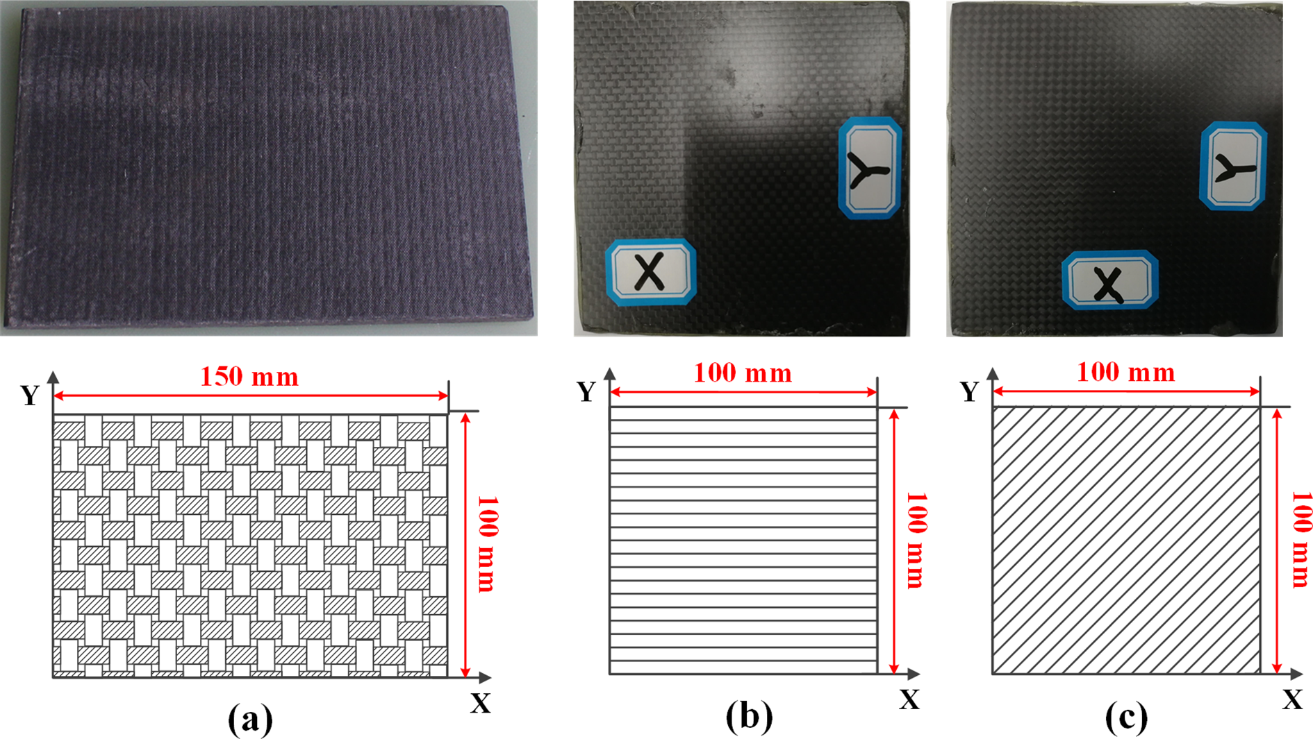
Tested CFRP specimens: (a) Carbon woven fabric/epoxy laminate; (b) unidirectional carbon fabric/epoxy laminate, [0]24; and (c) unidirectional carbon fabric/epoxy laminate, [45]24. CFRP: carbon fiber-reinforced polymer.
Experimental setup
The test fixture
The CFRP specimens (Type S1 to S3) were clamped along the length direction of the plane (X-direction), the width direction of the plane (Y-direction), and the thickness direction to measure the anisotropic dynamic conductivities of the CFRP laminates. The specimen fixture for measuring the through-thickness conductivities is shown in Figure 2(a). The CFRP laminate was sandwiched between the two copper plates which were used as positive and negative electrodes. The fixture in Figure 2(b) was used to measure the longitudinal and transverse conductivity by clamping specimens along its X- and Y-direction. The two symmetrical copper bars were positive and negative electrodes. The lightning current was injected into the specimen through the positive electrode. After conducting through the specimen, the lightning current gathered at the negative electrode and traveled back to the low-voltage terminal of the lightning impulse generator. To ensure the reliability of the experimental results, the surface of the copper electrode was polished with sandpaper before each test to eliminate the experimental error caused by the contact resistance. In addition, multilayer aluminum foils with high conductivity and soft texture were inserted between the electrode and the specimen. The aluminum foil interlayer can effectively fill the small air gap distributed on the contact surface between the electrode and the specimen and weaken the interference caused by the repeated breakdown occurred in the small gap to the voltage waveform.

The specimen fixtures used for clamping the CFRP laminate to measure the (a) through-thickness conductivity and (b) in-plane conductivity.
Lightning impulse generator and lightning waveforms
In this article, a lightning current impulse generator and test platform were used to study the dynamic conduction properties of CFRP laminates. The lightning current impulse generator consisted of a high-voltage capacitor C, waveform forming components (including the inductor L and the resistor R), trigger air gap switch, grounding system, and tested specimen, as shown in Figure 3.

The lightning current impulse generator.
The capacitance C, inductance L, and resistance R were connected in series. The film capacitance bank could be switched between 14 µF and 28 µF, and the waveform forming resistance and inductance could be continuously adjusted in the range of 0–5 Ω and 0–100 µH, respectively. This generator was capable of providing a lightning current impulse with amplitudes of 10 kV and 1.5 kA. The lightning current impulse could generally be defined by the waveform parameters of the front time (T f) and tail time (T t). The waveform parameters of 20/60 µs and 10/30 µs current impulses, including the front time, the electrical action integral, and the duration, satisfy the requirements of the standard lightning components A and D, respectively. Moreover, for the lightning components B and C with longer rise time, the 40/120 µs current impulse was selected in this experiment to further analyze the variation law of conductive characteristics with the waveform parameters. These current impulses with different waveform parameters can be generated by adjusting the modulated resistance and inductance in the RLC series circuit. The parameters of the modulated components corresponding to these lightning current waveforms are listed in Table 2. Figure 4 shows the waveforms of 10/30 µs, 20/60 µs, and 40/120 µs lightning current impulses.
The parameters of the modulated components corresponding to different lightning current waveforms.


Lightning impulse waveforms and parameters: lightning impulses of (a) 10/30 μs; (b) 20/60 μs; and (c) 40/120 μs. I p: peak value; T f: front time; T t: duration time.
The Rogowski coil, voltage impulse divider, and Tektronix MDO3012 oscilloscope were used to measure the lightning current impulse flowing through the tested CFRP specimens and the corresponding applied voltage impulse. The dynamic conductivities of the CFRP laminates clamped in different directions subjected to lightning current impulses with different amplitudes and parameters were measured. Then, the influences of the stacking sequence, clamping direction, and applied lightning current parameters on the dynamic impedance properties of CFRP laminates could be analyzed. In addition, to verify the reliability of the test data, the conductive property of CFRP specimen was tested twice at each current amplitude and the average was adopted to be the conductivity result. The conductivity of another CFRP laminate with the same structural parameters as the specimen in this experiment was measured under the same test conditions to analyze the dispersion of the test results between different laminates. The original experimental data can be found in “Supplementary Information: Part II” and “Part III.”
Experimental results
The nondestructive lightning current test
Via repeated measurements, it can be tested and verified that lightning current impulses with lower amplitudes do not cause irreversible damage to the conductive properties of CFRP specimens. In addition, when the lightning current conducts inside the CFRP laminate, the specimen is heated because of the generated Joule heat, which can be calculated by

The surface temperature on specimen after lightning current conduction (20/60 μs lightning impulse, I peak = 1.5 kA): (a) Surface temperature distribution (t = 165 μs) and (b) maximum surface temperature varies with the lightning current injection time t.
It can be seen from the simulated results that the temperature of CFRP specimen increased from the initial value 25°C to 31.7°C (t = 165 µs) under lightning impulse of 1.5 kA. Generally, the resin matrix pyrolyzes when the temperature exceeds 180°C to 200°C (aerobic conditions) and the carbon fibers sublime at the temperatures approaching 3300°C. 32 Therefore, the temperature increase of the CFRP laminate subjected to the low-intensity lightning current impulse can be neglected and does not cause irreversible damage to the CFRP material. Additionally, the surface temperature distribution of specimen S2 before the lightning test and after 10 consecutive lightning tests was measured using a handheld infrared radiation thermometer (Fluke Ti125, measuring range −20°C to 350°C) to verify our estimation of the temperature increase, as shown in Figure 6. It can be seen that the measured maximum temperature on CFRP specimen is 30.2°C, which means no significant temperature increase after the lightning current strikes.
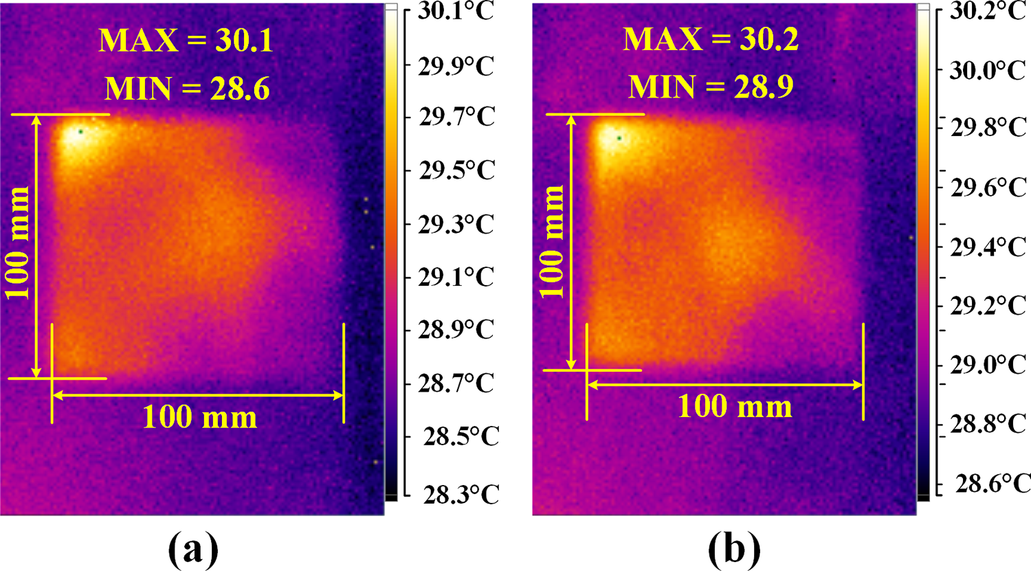
Temperature distributions of specimen S2. (a) Before the lightning test and (b) after 10 consecutive lightning tests.
The applied lightning current impulse and the responding voltage impulse
The dynamic conductive properties are distinctly affected by the applied lightning waveform parameters, the laminated structures, and the specimen clamped directions, but there are some similarities in the relationship between the lightning current and the responding voltage impulse. For instance, when specimen S1 is struck by a 20/60 µs lightning impulse, it can be seen that the voltage impulse waveforms are similar in shapes to the current waveforms for different specimen clamping methods, as shown in Figure 7. In addition, all the current impulses flowing through the CFRP laminate lag behind the responding voltage applied on the specimen, which means that when the voltage impulse reaches its peak value, the lightning current impulse is still in its increasing stage and will reach the peak after a period of time.
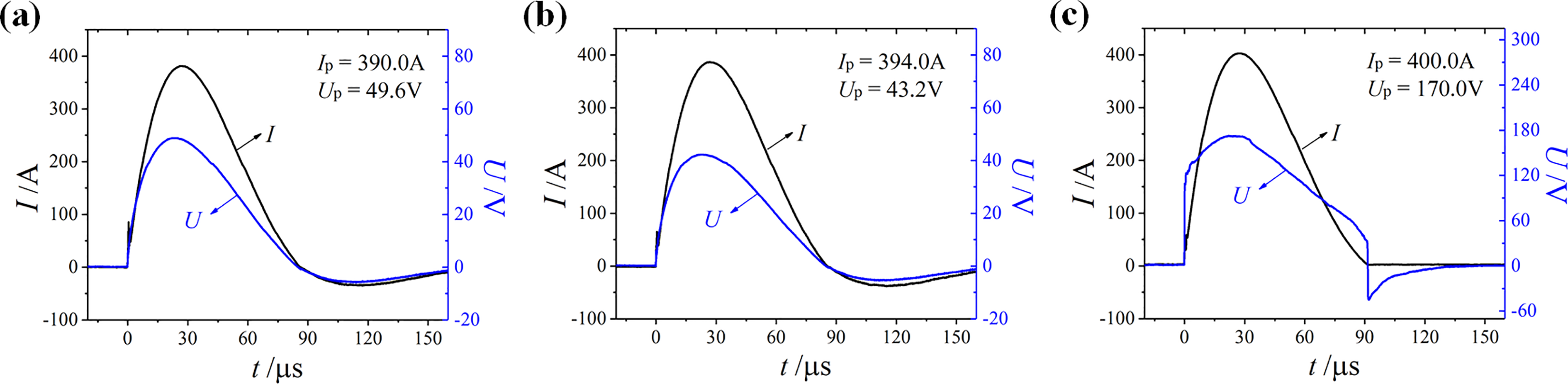
Current and voltage impulse waveforms of specimen S1 with different clamping methods: (a) In the X-direction of the plane; (b) in the Y-direction of the plane; and (c) in the thickness direction. I p: peak value of the current impulse; U p: peak value of the voltage impulse.
The dynamic volt–ampere characteristics of CFRP laminates can be obtained by analyzing the single lightning conducting process. Figure 8 shows obvious noncoincidence during the increasing and decreasing stages of the lightning current. Specifically, the voltage on the CFRP laminate during the current decreasing stage is significantly smaller than that in the current increasing stage. In addition, in the initial increasing stage of the lightning current, when the current flowing through the CFRP specimen increases to 30 A, the voltage on the laminate abruptly changes from 0 to greater than 110 V. In comparison, as the current increases from 30 A to 400 A, the voltage only increases by approximately 60 V. It can be inferred that the CFRP laminate has a large initial impedance in the thickness direction before it can conduct stably, and the impedance abruptly decreases when the voltage applied on the laminate reaches a critical value.

The dynamic volt–ampere characteristics of specimen S1 in the thickness direction with a 20/60 μs lightning current impulse applied.
Equivalent conductivity of CFRP laminates subjected to different lightning impulses
To quantitatively compare the conductivities of specimens subjected to lightning impulses with different waveform parameters and intensities, the equivalent conductance G = I
peak/U
peak was defined and calculated to represent the conductive property of the CFRP laminate, temporarily ignoring the phase difference between the current and voltage impulses. Then, the anisotropic conductivities

The equivalent conductivity of specimen S1 under the different lightning current impulses: (a) Longitudinal conductivity; (b) transverse conductivity; and (c) through-thickness conductivity.
From the experimental results in Figure 8, it can be seen that: With the increase in the peak value of the lightning impulse, the equivalent conductivity increases gradually, which indicates that the CFRPs have significant nonlinear conductive properties. The conductivities of the CFRP laminates in the X- and Y-directions are three orders of magnitude larger than the through-thickness conductivity. This can be explained by the inference that the in-plane current inside the laminate is mainly conducted through the highly conductive carbon fibers and the through-thickness conductivity is weakened because of the insulating interlaminar resin. The equivalent conductivities of the CFRP laminates are different under the lightning current impulses with different waveform parameters. Specifically, the conductivity of the CFRP laminate increases with decreasing rate of increase and increasing duration of the applied lightning current impulse.
Equivalent conductivity of CFRP laminates with different laminated structures
The CFRP laminates demonstrated different responses to lightning impulses due to their different laminated structures. For instance, for specimen S2 with a stacking sequence of [0]24, when it is clamped along its length direction (X-direction), the conductivities of the 0° laminated structure can be measured. The measured results for the same specimen S2 clamped in the width direction (Y-direction) correspond to the electrical conductivities of the 90° laminated structure. Similarly, the conductivities of the 45° laminated structure can be obtained from the in-plane conductivities of specimen S3. Figure 10 shows the equivalent conductivities of the 0°, 90°, and 45° laminated structures subjected to different lightning impulses.

The equivalent conductivities of the 0°, 45°, and 90° laminated CFRP structures subjected to lightning impulses of (a) 10/30 μs; (b) 20/60 μs; and (c) 40/120 μs.
The test results in Figure 10 indicate that the CFRP laminate has the best electrical conductivity along the longitudinal direction. The transverse conductivities (90° laminated structure) are at the lowest level. However, it is worth noting that the in-plane conductivities in different directions are on the same order of magnitude, but they are three orders of magnitude higher than the through-thickness conductivity.
Discussions
The conduction path of the CFRP laminate under a lightning current impulse
From the experimental results in sections “Equivalent conductivity of CFRP laminates subjected to different lightning impulses” and “Equivalent conductivity of CFRP laminates with different laminated structures,” the through-thickness conductivity of the CFRP laminate is found to be much smaller than the in-plane conductivities. Additionally, the conductive properties along different directions are closely related to the internal layup structure. CFRP laminates are usually cured by carbon fiber preimpregnated sheets. First, the carbon fiber prepreg should be cut to a certain size. Then, according to the designed layup structure, the carbon fiber prepreg is laid in the mold frame-coated with the release agent. Finally, the upper and lower mold frames are combined and placed in a flat vulcanizing machine for curing. The fiber monofilament inside the CFRP laminate is not completely straight, which causes random contacts between curved fibers, as shown in Figure 11. 24

Schematic model of the actual carbon fiber network inside the CFRP laminate: (a) In the single layer and (b) side view of the CFRP laminate.
In the same layer inside the CFRP laminate, the carbon fiber monofilaments are placed in two different ways. The fibers may directly contact other fibers, or they may be separated by a thin insulating matrix layer. The in-plane conduction of current mainly depends on the conductive network composed of fiber monofilaments, but the conductive paths are different in different laminated structures. 33,34
Since the current can be conducted along the relatively intact carbon fiber, the longitudinal conductivity is the highest. The electrical conductivity can be calculated according to the volume density of the carbon fibers in the CFRP laminate. 24,35 When lightning current is injected into laminates with other in-plane directions, such as 45° or 90°, the conductive network connected by part of the carbon fibers and the random contact points between fibers is incomplete. The thin resin layer can connect the fiber monofilaments that are distributed parallel, and the conductive path comprising carbon fibers, thin resin layers and direct contact points between fibers can be completed. The schematic of the current conduction path in the 90° laminated structure is shown in Figure 12, and a similar pattern for the conduction path exists in the 45° laminated structure. The in-plane conductivities in different directions differ only in the length of the conductive paths. Thus, they are on the same order of magnitude as the conductivity of the 0° laminated structure. In comparison, the through-thickness conductivity is approximately three orders of magnitude lower than the in-plane conductivity due to the thick interlaminar resin layer with poor conductivity.

Schematic model of the current conduction path in a 90° laminated structure.
Dynamic conductance of CFRP laminate
During the conducting process of the 20/60 µs lightning current impulse, the through-thickness conductance of CFRP specimen S1 is shown in Figure 13.
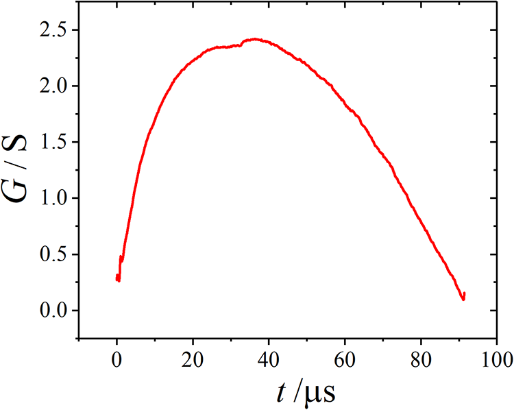
The dynamic through-thickness conductance of CFRP specimen S1.
The through-thickness conductance increases first and then decreases during the single lightning strike process, and the trend is basically consistent with the lightning impulse waveform. The through-thickness conductive path can be simplified to a series circuit of the carbon filament network and epoxy resin layers. Thus, the total equivalent conductance (G l) of the CFRP laminate can be estimated as:

where G c is the conductance of the carbon fibers connected in the conductive path and G r is the equivalent conductance of the resin layers. There is a significant difference between the conductivities of carbon fibers (103 S/mm) and insulating resin (10−9 to 10−13 S/mm), namely, G c >> G r. Then, equation (1) can be simplified as G l ≈ G r. Therefore, the conductive properties of the resin layer greatly affect the dynamic variation rule of the CFRP conductance G l with the applied voltage impulse.
The resin material is an insulating material accompanied by a low electrical conductivity. In the initial stage of lightning impulse, the resin layer remains in a high-resistance state. Thus, most of the discharge voltage, which is on the order from 102 to 103 V, is distributed on the specimen, and the current flowing through the specimen is at a very low value. The loaded voltage on the CFRP specimen may induce interior electrical carriers inside the laminate that can participate in the current flowing process and lead to an improvement in the conductivity of resin layers. With the continuous application of voltage impulses and an increase in electrical carriers injected from the external circuit, the conductivity of the resin layer increases gradually, and then the overall conductivity increases. In the voltage decrease stage, when the electric field intensity decreases to a value that is insufficient for maintaining conductive carriers inside the resin material, electrical carriers such as free electrons and electric doublets steadily dissipate, and the material conductivity decreases and returns to the original state. Therefore, it can be inferred that the varying regulation of the conductivity of the resin material with the applied impulse intensity is one of the key factors that cause nonlinear behavior in the conductivities of CFRPs subjected to lightning impulses.
At the initial moment of lightning current generation, the voltage applied on the CFRP specimen can reach 1–4 kV according to the test conditions. However, in the static DC conductivity test, the test voltage used is only on the order of 100–101 V. 21 Therefore, there is a distinct difference between the dynamic conductive properties of CFRP laminates subjected to lightning current impulses and their DC static conductivity properties. According to the experimental results of section “Equivalent conductivity of CFRP laminates subjected to different lightning impulses,” the electrical conductivities of 0° and 90° laminated structures are both on the order of 100 S/mm, and the through-thickness conductivity is on the order of 10−3 S/mm. The conductivities increase as the lightning current intensity increases. In comparison, in the DC conductance tests of the CFRP laminates, the measured static DC conductivities along the 90° laminated direction and in-thickness direction are both poor since the interfibrillar resin and the resin layers between adjacent carbon fiber layers are in an insulating state under the applied low magnitude DC voltage. Specifically, the DC conductivities in the longitudinal and transverse directions of the CFRP laminate are on the order of 101 S/mm and 10−4–10−3 S/mm, respectively, and the DC conductivity in the thickness direction is 10−7–10−6 S/mm. 12 –16 Therefore, the use of the DC conductive properties of CFRP materials in the simulated calculation of the coupled thermoelectrical model for the evaluation of CFRP lightning damage behavior may cause distortion in the simulation results.
The inductive properties of CFRP laminates
According to the experimental results in section “The applied lightning current impulse and the responding voltage impulse,” the phase of the voltage impulse applied on the CFRP laminate is ahead of the phase of the current impulse, and the dynamic volt–ampere curves of CFRPs do not coincide during the increasing and decreasing processes of the lightning current impulse. In addition, the lower the increase rate and the longer the duration of the lightning current impulse, the greater the equivalent conductivity of the CFRP laminates. These test results can be explained as follows.
The expression for the lightning current phase can be written as:

where

where R and L represent the equivalent resistance and inductance of the CFRP laminates. The applied voltage values during the increasing (U 1) and decreasing (U 2) processes of the lightning current impulse can be expressed as follows:

In equation (4), i 1 and i 2 are the current values in the increasing and decreasing processes of the lightning impulse, respectively. The deviation of the increasing and decreasing voltages is

When i 1 and i 2 are the same, i 1 = i 2. Considering that di 1/dt > 0 during the current increasing stage and di 2/dt < 0 in the decreasing stage, it can be concluded that U 1 − U 2 > 0. In other words, with the same current value, the voltage in the current increasing stage is larger than that in the decreasing stage, resulting in the noncoincidence phenomenon in the dynamic volt–ampere curves (Figure 8).
In addition, since the lightning current lags behind the voltage impulse, when the voltage reaches the peak value, the current is still in its increasing stage. Therefore, for lightning impulses with different waveform parameters (10/30 µs, 20/60 µs, and 40/120 µs), the values of di/dt are all positive at the peak of the voltage impulse. When the current amplitude is at the same value, the lower the increasing rate and the longer the duration of the lightning impulse are, the smaller the value of di/dt. Then, the applied voltage on the CFRP specimen obtained according to equation (4) decreases, and the equivalent conductivity of the CFRP specimen increases. Additionally, it should be noted that as the lightning current continues flowing through the CFRP laminate, the injection of electrical carriers from the external circuit can improve the conductivities of the resin layers inside the CFRP laminates. Therefore, the equivalent conductivity of the CFRP material increases as the duration of the lightning current impulse increases, that is,

The equivalent conductivity of the CFRP laminates under a lightning current impulse of 40/120 µs is the highest, followed by that under a 20/60 µs lightning impulse, and the conductive ability of CFRPs under a 10/30 µs lightning impulse is the worst.
As shown in section “The conduction path of the CFRP laminate under a lightning current impulse,” the current conduction path inside a single plane layer is mainly formed by the interconnection of carbon fiber filaments, although thin layers of resin may be interposed between the carbon filaments. Therefore, the inductive properties of CFRP laminates may be closely related to the electrical characteristics of the carbon fibers. The carbon fiber can be simply regarded as a straight conductive wire, and the equivalent inductance of the straight wire can be calculated as

where l is the length of the carbon fiber, r c is the radius of the carbon fiber (approximately 3.5 µm), and μ 0 = 4π × 10−7 H/m is the vacuum permeability. According to equation (7), the inductance of a carbon fiber monofilament with a length of 1 m is approximately 2.5 µH. When the current flows in the 90° laminated structure CFRP laminate with a size of 100 mm × 100 mm × 3.6 mm, it can be assumed that the length of the in-plane conductive path is approximately 2 × 100 mm. Thus, the equivalent inductance of the single conductive path formed by a carbon monofilament is approximately 2.5 µH/m × 2 × 100 mm = 0.5 µH.
The current conduction path inside a single layer is a parallel circuit formed by multiple carbon fiber conductive channels. However, not all carbon fiber filaments can participate in the lightning conducting process. Assuming that only 50% of the carbon fibers in the laminate are involved in the construction of the conductive path, the number of conductive fibers connected in the parallel circuit inside a CFRP laminate with a fiber volume fraction (f v) of 60% can be estimated as
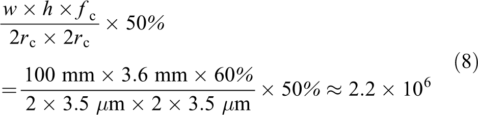
In equation (8), w and h are the width and height of the CFRP specimen respectively, and it is assumed that the cross section of the space that the carbon fiber occupies is a square with a side length of 2r c. When multiple carbon fiber wires are connected in parallel, the equivalent inductance of the circuit network is reduced to some extent. However, the equivalent inductance of the carbon fiber parallel circuit does not follow the inverse-proportion law to the number of parallel filaments. According to engineering experience regarding the inductance of parallel wire circuits, an increase in the number of parallel wires can only reduce the total inductance to approximately 60% of a single wire’s inductance due to the existence of mutual inductance between wires. It can be estimated that the equivalent inductance of the carbon fiber conductive network in the plane direction of the carbon fiber laminate is approximately 0.5 × 60% ≈ 0.3 µH. When the lightning current impulse of 20/60 µs with the peak value of 384 A is applied on CFRP specimen S1 (90° laminated structure), the voltage change due to the inductive effect of the carbon fiber conductive network can be calculated as

The total voltage on the CFRP laminate is measured to be approximately 35.2 V. The voltage decrease due to the inductive properties of the carbon fibers accounts for 32.2% of the total voltage on the tested CFRP specimen, which indicates that the inductive effect of the carbon fiber network has a significant influence on the dynamic conductive properties of the CFRP laminate.
Equivalent conductivity of CFRP laminates subjected to lightning current impulses with higher intensity
Based on the former experiment on the dynamic conductive properties of CFRP laminates subjected to nondestructive lightning current impulses, it can be found that the dynamic conductive properties of CFRP laminates are different under lightning impulses with different waveform parameters and amplitudes. For the destructive lightning direct effect test, because of the distinct difference in the waveform parameters of lightning current components stipulated in lightning test standards, 29,30 the equivalent conductivity of the CFRP material should be measured and calculated according to the specific lightning test environment. For instance, when lightning component A is applied, the dynamic equivalent conductivity of the CFRP laminate can be estimated based on its conduction properties under a lightning impulse of 20/60 µs, which has similar front time and duration parameters as lightning component A. From the test results of the equivalent conductivity of the [0]24 unidirectional CFRP laminate in Figure 9, the conductivity along the fiber direction was found to increase with the increase in lightning current peak value according to the power function law via the curve fitting method, as shown in Figure 14.

Relationship between the longitudinal conductivity of specimen S1 and the amplitudes of the 20/60 μs lightning impulse.
The relationship between the anisotropic equivalent conductivity of the unidirectional CFRP laminate and the lightning current amplitude can be calculated as follows:

As for the applied ranges of equation (10), first, it must be valid under the experimental conditions of current amplitude 50 A–1000 A and discharge voltage 100 V–4 kV. Additionally, equation (10) can be used to estimate the equivalent conductivities of CFRPs subjected to lightning current impulses with higher intensity if there is no resin pyrolysis, delamination, and other damage inside CFRP material. In the destructive lightning test, the change in conductivities caused by material heating and resin pyrolysis should be fully considered. With low intensity voltage applied, the resin layers distributed in the conduction path is an insulating material accompanied by a low electrical conductivity which is generally on the order of 10−9 to 10−13 S/mm. When the applied voltage is less than 50 V, the through-thickness resistance of CFRP specimen was found to be so large that the electrical energy can only be slowly released in the form of low-amplitude current, and cannot generate the current impulse with the expected waveform parameter. Therefore, it can be inferred that the conductivity of CFRP material does not conform to the law in equation (10) when the order of magnitude of the current intensity is lower than 100.
Conclusions
In this article, the dynamic conduction model of CFRP laminates subjected to lightning current impulses of low intensity was experimentally studied. Based on the analysis of the influence of the laminated structures, the current conductive path and the waveform parameters of lightning current impulses on the dynamic conductive properties of CFRPs, the conduction mechanism of CFRP laminates under the lightning current impulse is investigated. The main conclusions are summarized as follows:
The CFRP laminate has anisotropic conductivities due to its laminated structures. When the lightning current is conducted in the plane of the CFRP laminate (along the longitudinal or transverse direction of the CFRP laminate), the conductive network is mainly composed of high-conductivity carbon fiber filaments, and the adjacent carbon fibers are connected by direct contact points or a thin layer of resin. Since the interlaminar low-conductivity resin layer is thicker than the interfibrillar resin layer, the through-thickness conductivity (10−3 S/mm) is far lower than the in-plane conductivity (100 S/mm).
The dynamic conductance of the CFRP laminate is primarily determined by the conductivity of the resin material in the lightning current conduction path. The dynamic conductance of the CFRP laminate first increases and then decreases during the single lightning current strike process, which is closely related to the conductive properties of interlaminar resin materials whose conductive properties are a function of the applied voltage. Additionally, the nonlinear conductive properties of resin are one of the key factors that lead to nonlinear variation in the equivalent conductivity with the applied lightning current intensity.
A CFRP laminate can be regarded as a series circuit of an equivalent resistor and inductor. The inductive properties are exhibited in the CFRP laminate under the effect of the lightning current impulse, represented by the fact that the dynamic voltage is ahead of the current impulse in phase space and the increasing and decreasing stages of the volt–ampere curve do not coincide. Due to the equivalent inductance in the CFRP conduction circuit model, the conductivity of the CFRP laminate increases with a decrease in the rate of increase and an increase in the duration of the applied lightning impulse. The equivalent inductance of the carbon fiber network, which can be estimated by a circuit of parallel straight wires, plays an important role in the inductive properties of CFRP laminates. The voltage decreases in the carbon fiber inductance network account for approximately 32.2% of the total voltage on the tested CFRP specimen.
The dynamic conductive properties of CFRP laminates subjected to lightning impulses are quite different from the static DC conductance. Therefore, systematic and in-depth studies concentrating on the internal conduction mechanism of CFRPs under lightning impulses need to be performed to provide both experimental support and a theoretical basis for the application of the dynamic conduction model in coupled thermoelectric simulation for CFRP lightning direct effect research and improvement in material optimization and structural design.
Supplemental material
Supplementary_Information-Part_I - Dynamic electrical characteristics of carbon fiber-reinforced polymer composite under low intensity lightning current impulse
Supplementary_Information-Part_I for Dynamic electrical characteristics of carbon fiber-reinforced polymer composite under low intensity lightning current impulse by Jinru Sun, Xuanjiannan Li, Xiangyu Tian, Jingliang Chen and Xueling Yao in Advanced Composites Letters
Supplemental material
Supplementary_Information-Part_II - Dynamic electrical characteristics of carbon fiber-reinforced polymer composite under low intensity lightning current impulse
Supplementary_Information-Part_II for Dynamic electrical characteristics of carbon fiber-reinforced polymer composite under low intensity lightning current impulse by Jinru Sun, Xuanjiannan Li, Xiangyu Tian, Jingliang Chen and Xueling Yao in Advanced Composites Letters
Supplemental material
Supplementary_Information-Part_III - Dynamic electrical characteristics of carbon fiber-reinforced polymer composite under low intensity lightning current impulse
Supplementary_Information-Part_III for Dynamic electrical characteristics of carbon fiber-reinforced polymer composite under low intensity lightning current impulse by Jinru Sun, Xuanjiannan Li, Xiangyu Tian, Jingliang Chen and Xueling Yao in Advanced Composites Letters
Footnotes
Declaration of conflicting interests
The author(s) declared no potential conflicts of interest with respect to the research, authorship, and/or publication of this article.
Funding
The author(s) disclosed receipt of the following financial support for the research, authorship, and/or publication of this article: This work was financially supported by the National Natural Science Foundation of China (grant numbers 51477132 and 51521065).
Supplemental material
Supplemental material for this article is available online.
References
Supplementary Material
Please find the following supplemental material available below.
For Open Access articles published under a Creative Commons License, all supplemental material carries the same license as the article it is associated with.
For non-Open Access articles published, all supplemental material carries a non-exclusive license, and permission requests for re-use of supplemental material or any part of supplemental material shall be sent directly to the copyright owner as specified in the copyright notice associated with the article.