
Abstract
Ultrasonic bonding is a convenient bonding technology, which features sufficient cleanliness, high efficiency, no need for additional bonding aids, and other outstanding advantages. In recent years, it has been introduced into the field of the micro–nano assembly of polymer micro–nano devices, but it is still difficult for current ultrasonic bonding technology to meet the accuracy requirements of the micro–nano assembly. To improve the control accuracy of the hot-melt interface in the process of ultrasonic bonding, an online hot-melt interface monitoring method and an online ultrasonic transmission efficiency detection method are proposed in this article. With these detection methods, the real-time monitoring of the hot-melt interface can be realized on the basis of machine vision, while high-frequency dynamic force sensors can be used to detect the ultrasonic vibration transmitted from the ultrasonic horn to the anvil. Based on these methods, a functional anvil based on visual monitoring and ultrasonic detection is developed, the finite element method has been used to analyze the transmission characteristics of ultrasonic vibration, and experiments are carried out regarding online detection in the process of ultrasonic bonding. The results show that this system can realize the online detection of the hot-melt interface and ultrasonic transmission information, providing a new control method for ultrasonic bonding technology.
Introduction
Polymer materials are widely used in many fields. Certain polymer materials (such as polyethylene [PE], polymethyl methacrylate [PMMA] and polydimethylsiloxane [PDMS]) have been selected as basic manufacturing materials by virtue of their low melting points, low conductivity, low cost, easy machining, and so on, and polymer bonding technology is playing an important role in the field of micro–nano manufacturing. Therefore, polymer micro–nano bonding technology, which is high in precision and efficiency, is of great significance for research.
At present, the main welding technologies are external heating welding, electromagnetic heating welding, and internal heat welding. Specifically, hot plate welding, 1 hot gas welding, 2 laser welding, 3 and thermal bonding 4 belong to external heating welding technology, while radio-frequency welding and microwave welding 5 belong to electromagnetic heating welding technology, and friction welding 6 and ultrasonic welding 7 belong to internal heat welding technology. Since the discovery of the ultrasonic welding process in 1958, ultrasonic welding has been applied to bond the same or different materials. In the process of ultrasonic welding, the hot-melt behavior only occurs at the contact interface and has high efficiency in heat production and little impact on the deformation of the structure. It can complete bonding in just a few seconds. Also, it facilitates batch processing without any auxiliary agent or pretreatment and is able to avoid biochemical compatibility with low costs and flexible process, by virtue of which ultrasonic precision bonding technology has broad application prospects in the field of micro–nano bonding. 8
In 2006, ultrasonic precision bonding technology was applied in the field of micromachining. Truckenmuller et al. 9 were the first to realize the complete bonding of a PMMA microfluidic chip using ultrasonic precision bonding. Kim et al. 10 studied ultrasonic precision bonding technology for metal and polymer micro devices, respectively, and realized the bonding of cellulose acetate micro devices. Ng et al. 11 used ultrasonic precision bonding technology to complete the bonding of PMMA microtubules and microchips and solved the problem of microchannel blocked by the melt material in the bonding process. In the abovementioned research, ultrasonic precision bonding is basically subject to such traditional open-loop control methods as time, energy, and stroke, which are directly related to ultrasonic loading conditions. Masuzawa and Ohdaira 12 studied the acoustic information scattered in the surrounding air in the process of ultrasonic precision bonding, then used it to monitor real-time changes in the state of the interface materials, but this technique has not subsequently been widely applied or discussed. Sun et al. 13 applied the ultrasonic detection function to control the ultrasonic precision bonding process of polymer micro devices and proposed a bonding method based on ultrasonic transmission efficiency feedback; this method improved the controllability of the interface fusion effect, with the vibration transmission taken as the feedback parameter for process control. Luo et al. 14 used the thermal assistant method to realize the ultrasonic bonding of four-layer microfluidic chips, then built a multi-interface temperature testing device and tested the temperature fields of three bonded interfaces by means of thermocouple embedding. They then studied and compared the temperature of each interface under single ultrasonic action and thermal assistant ultrasonic bonding, thereby generating useful references for research on mechanisms for the ultrasonic multilayer bonding of polymer microfluidic devices. Parmar and Pandya 15 applied the analysis of variances to optimize the parameters by the center composite method of the response surface methodology. Wang et al. 16 carried out ultrasonic welding tests of an injection molded short carbon fiber-reinforced composite to investigate three important weld attributes, bonding efficiency, weld area, and horn indentation. The microstructure was examined to study cross sections and the fracture surface of the welded joints in the ultrasonic bonding process. Sun et al. 17 proposed a two-step bonding process, including frictional heating and viscoelastic heating, divided by the vibration propagation which is designed to achieve a whole fusion bonding interface with the flaws being well restrained.
At present, in research on the ultrasonic bonding of polymers, ultrasonic welding is basically subject to such traditional open-loop control methods as time, energy, and stroke, but there is no in-depth research on closed-loop control. To improve the control accuracy of the hot-melt interface in the process of ultrasonic bonding, an online hot-melt interface monitoring method and an online ultrasonic transmission efficiency detection method are proposed in this article. With these detection methods, the real-time monitoring of the hot-melt interface can be realized on the basis of machine vision, while high-frequency dynamic force sensors can be used to detect the ultrasonic vibration transmitted from the ultrasonic horn to the anvil. Based on these methods, a functional anvil based on visual monitoring and ultrasonic detection is developed, the finite element method is used to analyze the transmission characteristics of ultrasonic vibration, and experiments are carried out regarding online detection in the process of ultrasonic bonding. The results show that this system can realize the online detection of the hot-melt interface and ultrasonic transmission information, providing a new control method for ultrasonic bonding technology.
The structure of this article is as follows: the second section mainly introduces the design and development of the experimental platform for ultrasonic precision bonding monitoring. The third section covers the finite element analysis of the characteristics of ultrasonic vibration transmission. Finally, the fourth section covers the experiments on the online detection of the hot-melt interface and ultrasonic transmission information.
Experimental platform design
The vision information of the hot-melt interface directly reflects its fusion state, and the vibration information transmitted by ultrasonic waves in polymer devices is also deeply related to the fusion state of the interface. To realize the visual monitoring of the hot-melt interface in the ultrasonic precision bonding of polymers, and the extraction of the vibration characteristics of ultrasonic transmission in polymer micro devices, an experimental platform is designed for online visual monitoring and ultrasonic feedback detection during the ultrasonic precision bonding of polymers. As shown in Figure 1, the experimental ultrasonic bonding platform is mainly composed of a motion control module, ultrasonic loading system, anvil, and functional base integrated with high-speed vision and dynamic force measuring system.

Ultrasonic bonding platform with integrated visual monitoring and ultrasonic detection.
Based on displacement pressurization, the motion control module is used to drive the ultrasonic horn to move longitudinally and provide bonding precompression. The module is composed of a stepper motor, linear motion guide rail, and ultrasonic horn holder. The ultrasonic horn is fixed on the linear motion guide rail and controlled by the stepper motor. Compared with traditional pneumatic pressurization, in this mode, the force of the horn loaded on the sample can be controlled more accurately, and interference from pressure fluctuation can also be avoided.
The ultrasonic loading module consists of an intelligent ultrasonic generator, transducer, and ultrasonic horn. It uses an ultrasonic system that has a working frequency of 60 kHz with the amplitude subject to digital control, in which the generator is used to provide ultrasonic energy. As the key component, the ultrasonic transducer can convert electrical energy into the mechanical energy of ultrasonic vibration, and its electrical energy comes from the ultrasonic generator. The ultrasonic horn transfers the ultrasonic mechanical energy to a micro device on which it exerts working pressure.
The anvil module, which integrates the online monitoring function, has two main functions: the visual monitoring of the hot-melt interface and the detection of ultrasonic transmission characteristics. The visual monitoring function mainly relies on an OSG030-815UM superspeed industrial CMOS camera (YVSION, Shenzhen, China). Moreover, the higher the frame rate, the worse the resolution, while the higher the resolution, the clearer the image, so this experiment uses 815 frames per second (FPS), which can provide the highest resolution and clearest imaging and meet the requirements for monitoring changes in the physical state of the hot-melt interface; the specific parameters are listed in Table 1. This visual sensor can meet the requirements for monitoring the process for dynamic changes, namely changes in the state of the PMMA hot-melt interface in the polymer ultrasonic precision bonding experiment. Besides, the design of the ultrasonic monitoring function mainly includes a dynamic force sensor, charge amplifier, data acquisition card, and so on. The dynamic force sensor uses a piezoelectric dynamic force sensor, the specific parameters of which are given in Table 2. The piezoelectric dynamic force sensor can convert the detected high-frequency dynamic force signal into a weak current signal which is transmitted to the data acquisition card after amplification in the charge amplifier. The voltage signals output from the dynamic force sensor are all transmitted to the industrial computer via the data acquisition card so as to acquire and store data of the high-frequency dynamic force on micro devices in the process of high-frequency vibration.
Parameters of visual sensor.

Parameters of dynamic force sensor.

Finite element analysis
To use finite element simulation to analyze the vibration information of the vibratory force transmitted to the dynamic force sensor under the influence of the temperature rise and thermal expansion of the fusion layer during ultrasonic bonding, simulation modeling was completed in accordance with the actual experimental platform, as shown in Figure 2. The finite element analysis model established during ultrasonic precision bonding includes the ultrasonic horn, specimen, substrate, clamping base, sleeve, anvil, and dynamic force sensor, as shown in Figure 2.

Finite element model of anvil with integrated visual monitoring and vibration detection.
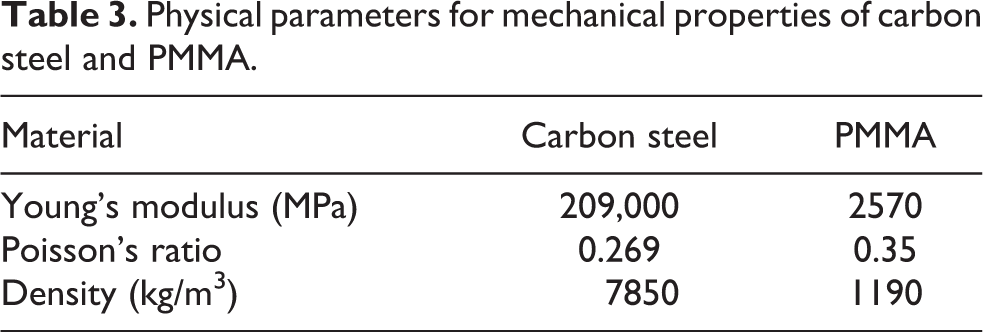
Specifically, the ultrasonic horn, clamping base, sleeve, camera base, and dynamic force sensor are made from carbon steel, and the test piece and substrate are made from PMMA; see Table 3, for the parameters of the two materials. In the simulation test, the size of the connecting pipe is consistent with the actual part; that is, the outer diameter is 4 mm, the inner diameter is 1 mm, and the height is 2 mm. The whole structural hexahedron has 5296 finite element grids.
Physical parameters for mechanical properties of carbon steel and PMMA.
In the simulation process, the translational degree of freedom (U2) changes on the Y-axis due to the fusion of the hot-melt interface. The other directions including the translational degrees of freedom U1 and U3 of the X and Z axes and the rotational degrees of freedom UR1, UR2, and UR3 of the X, Y, and Z axes are all fixed. The contact surfaces are all set in surface-to-surface contact, and the friction coefficient is set to 0.15. The camera is ignored in the simulation, because it doesn’t bear the force from the ultrasonic horn. The grid type is set to hexahedron whose size is set according to the components, and the total number of the elements in the whole structure is 5296.
The ultrasonic precision bonding of polymer micro devices proceeds as follows: ultrasonic energy is transferred from the ultrasonic horn to the micro devices, and the bonding interface becomes locally hot under the action of the friction effect and viscoelastic thermal effect, causing the temperature of the interface to rise sharply in a short time; the polymer material starts glass transition when it reaches glass temperature and then a fusion layer is formed, completing the bonding of the micro devices under the action of pressure. In the finite element model, a 0.2-mm-thick viscoelastic fusion layer is set at the bottom contact of the connecting pipe; this is because the heat generated on the bonding interface during ultrasonic precision bonding only affects the transformation of the material state in the fusion layer area, namely the transition from the glass state to the viscoelastic state with typical viscoelastic mechanical properties.
The technological parameters of ultrasonic precision bonding, such as amplitude, frequency, and precompression, affect the temperature rise rate of the interface by affecting the scale of the ultrasonic energy, leading to the transformation of the material state of the bonding interface, which then affects the transmission of vibration. Therefore, in the simulation test, the other parameters remained unchanged, and only the temperature change of the fusion layer was taken as an independent variable. Considering the influence of the thermal expansion of polymer materials, the thermal expansion properties of PMMA materials were set, and the thermal expansion coefficient of PMMA with temperature changes can be found in the work of Yilong. 18 The viscoelastic fusion layer is the key factor affecting vibration transmission. Due to the rise in temperature, its mechanical properties will change significantly. Zhu 19 reported the stress relaxation curve of the viscoelastic material PMMA at different temperatures.
In the ultrasonic bonding process of polymers, bonding mainly occurs in the fusion layer. Moreover, the fusion layer features typical viscoelasticity, and its mechanical state changes with the increase of the interface temperature and ultrasonic amplitude. Therefore, the force will change accordingly on the hot-melt interface of the specimen, so the contact force will be transmitted to the vibration sensor.
To study the stress state of the fusion layer in the simulation process, the ultrasonic loading amplitude was first set at 1 µm, and the representative stress states of the polymer material in the ultrasonic loading analysis were detected at 40°C, 110°C, and 135°Cat near room temperature, glass transition temperature (T g), and viscous transition temperature, respectively. Next, the stress distribution nephogram between the vibration sensor and the anvil’s contact surface was extracted after ultrasonic loading was complete at the representative 110°C. As can be seen from the stress simulation results, the stress distribution at 40°C and 135°C was exactly the same as that at 110°C, but only the numerical values were different, and the stress distribution was mainly concentrated at the edge, as shown in Figure 3. At 40°C, the maximum stress on the vibration sensor was about 0.39 MPa; the maximum stress of a thermoplastic polymer is about 0.64 and 0.095 MPa at 110°C and 135°C, respectively, indicating that the stress between the vibration sensor and the anvil’s contact surface tends to rise first and then drop accordingly after ultrasonic loading is complete.
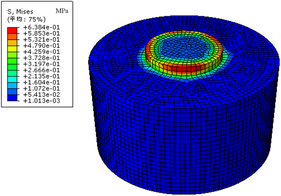
Simulation results of stress distribution on typical dynamic force sensors.
According to the output results of the calculation simulation process, see Figure 4(a) to (c) for the vibration status between the vibration sensor and the anvil’s contact surface of each model at three different temperatures—40°C, 110°C, and 135°C—under the action of a 60-kHz and 1-µm high-frequency ultrasonic wave. In all three figures, when the ultrasonic wave has just loaded, the figures shake for a short period at the beginning, then the contact force soon tends to become stable, and the three groups of contact forces at 40°C, 110°C, and 135°C are completely different. At 40°C, the contact force vibrates with an amplitude of about 0.2 N at the center of 4.65 N, with a maximum and minimum vibration peak value of about 4.85 N and 4.5 N, respectively; at 110°C, the contact force vibrates with an amplitude of about 0.5 N at the center of 7.7 N, with a maximum and minimum vibration peak value of about 8.3 N and 7.2 N, respectively; however, at 135°C, the contact force reduces significantly, its vibration center decreases to about 1.155, and the maximum and minimum values decrease to about 1.16 N and 1.15 N, respectively. As can be seen from the three groups of figures, under constant amplitude, the vibration center and peak value change significantly with the increase in temperature, indicating that the dynamic force between the dynamic force sensor and the anvil is always changing with the increase in the temperature of the interface during the whole bonding process, with a change process of first increasing and then decreasing. Therefore, the anvil integrated with online monitoring has a structural design suited to monitoring ultrasonic transmission.

Simulation results of vibratory force on dynamic force sensor at (a) 40°C, (b) 110°C, and (c) 135°C.
Experimental results and discussion
To carry out the online monitoring of the hot-melt interface and ultrasonic transmission efficiency during polymer ultrasonic bonding, the images resulting from the online monitoring of the hot-melt interface and the vibration force waveform are extracted simultaneously, and comparative analysis is carried out to identify the close connection between the dynamic characteristics and the state of the hot-melt interface during the bonding process.
After testing is complete on the ultrasonic bonding platform, we can clearly monitor changes in the physical states of PMMA micro devices during the bonding process using video images captured by the visual sensor, including bubbles and holes occurring on the hot-melt interface during the bonding process, as well as the fusion degree and other basic conditions of the hot-melt interface, as shown in Figure 5. According to the real-time images captured by the visual sensor, two groups were selected for bonding tests. In each group of tests, images of the same three stages were captured with ultrasound applied for 1.5 s, 5.2 s, and 9 s, respectively. As can be seen from the three time points, the fusion degree of the hot-melt interface of the PMMA micro devices increases significantly with the increase of time. When the ultrasound is applied for about 1.5 s, it can be seen from the figure that there is no obvious fusion of the hot-melt interface, and only the edge of the PMMA micro devices tends to fuse; moreover, when the ultrasound is applied for about 5.2 s, it can be seen from the figure that the fusion degree remains at about 55–65% and that the hot-melt interface tends to fuse from the edge to the middle; furthermore, when the ultrasound is applied for about 9 s, the hot-melt interface of the PMMA micro devices is basically fused completely. According to the results from three different stages of the two test groups, the ultrasonic bonding test platform can basically meet the objectives and requirements of its design.

Ultrasonic bonding monitoring images of functional anvil based on visual monitoring and ultrasonic detection.
In the ultrasonic bonding process of PMMA micro devices, as the temperature increases on the interface subject to ultrasonic bonding, the component being welded will start to change from its glass state into its high-elastic state and then into its viscous flow state. The dynamic force curve of PMMA micro devices under the action of loaded high-frequency ultrasonic vibration of 60 kHz can be obtained via the piezoelectric dynamic force sensor.
The vibration stress extracted from the test is output in the form of output voltage because the piezoelectric pressure sensor uses the piezoelectric effect of piezoelectric materials to convert the measured pressure into an electrical signal. There is a linear relationship between the amount of charge and the force generated when piezoelectric elements are subject to pressure: in the formula q = ksp, in which q is the amount of charge, k is the piezoelectric constant, s is the area of action, and p is the pressure. The measured pressure can be determined by measuring the electric charge. In the experiment, the piezoelectric dynamic sensor was used to measure the amount of charge, then the charge amplifier was used to amplify the charge and convert it into voltage output, with the output signal corresponding to the measured pressure.
In the original vibration waveform extracted from the experiment, the energy components are rather complicated and it is difficult to observe the features contained in the vibration information, as shown in Figure 6, so finite impulse response filter control was applied for online filtering. Moreover, the vibration information energy extracted by the experiment is mainly concentrated in the 60-kHz frequency band, so the band-pass filter was selected and only the vibration signal in the 60-kHz frequency band was retained.

Original waveform of ultrasonic vibration extracted from the functional anvil based on visual monitoring and ultrasonic detection.
From Figure 7, regarding the image after online filtering, it can be seen that the overall trend is as follows: it first increases to the highest point, then decreases, then increases to another peak, then decreases again, and finally tends to become stable. Its vibration amplitude starts to have a small peak at about 2 s, the peak value reaches its maximum with the fiercest vibration at 5 s, and then the vibration slowly tends to become stable at 8 s and reduces to 0.

Vibration waveform extracted after filtering at 60-kHz frequency band.
In the simulation, the temperature of 40°C corresponds to the 1.5-s interfacial fusion images in Figure 5. In this state, the bonding surfaces do not fit fully due to the micro surface roughness but contact with each other in local region, which results in the occurrence of small dynamic force. When the simulation temperature rises up to 110°C, it corresponds to the 5.2-s interfacial fusion images in Figure 5. This point corresponds to the glass transition of PMMA. In the process of interfacial temperature rising up from room temperature up to T g, the volume expansion increases with the temperature rising for PMMA in glassy state. As the bonding pressure is provided from linear guide in the ultrasonic bonding platform, which is a kind of displacement control mode. So, the dynamic force is equivalent to increase with the expansion of PMMA components. Subsequently, in the condition of interfacial temperature reaching 135°C, it corresponds to the 9-s interfacial fusion images in Figure 5. The interfacial PMMA starts to convert into viscous flow state. The local material near fusion interface gets soften and the bonding structure deforms seriously. In this kind of displacement control mode, the precompression is decayed by the deformation, and the dynamic force from ultrasonic horn decreases gradually and to zero eventually.
The vibration waveform extracted from the experimental results corresponds with the simulation results, which verifies the accuracy of the dynamic force changes in the simulation results. At the same time, it is basically consistent with the results from the earlier research and analysis of the research group on the characteristics of ultrasonic vibration, which shows that the laws of this experiment are consistent with the results of the previous experiment.
Comparing the visual monitoring results and the vibration waveform, the interface starts to fuse at about 1.5 s but interfacial fusion doesn’t form. At this point, the amplitude of vibration waveform at 60-kHz frequency band from Figure 7 increases as the ultrasonic energy is turned on. With continuous ultrasonic loading, interfacial fusion reaches 50% at 5.2 s. In this condition, the amplitude of the vibration waveform at 60 kHz increases nearly five times larger than the initial value. It is related to the glass transition of PMMA components. Then at 9 s, the interfacial fusion exceeds 98% and the rest 2% consist of bubbles caused by the cavitation effect under ultrasonic load. The amplitude of vibration waveform at 60 kHz drops gradually and lower than the initial value eventually. At this stage, PMMA components are at viscous flow state. So, the effect from ultrasonic horn is weakened in the displacement control mode employed in this article. Meanwhile, as the fluidity of PMMA components increase at viscous flow state, compressive and tensile stress in high frequency is imposed on the fusion interface under ultrasonic load. As a result, the ultrasonic cavitation produces a marked effect to generate small bubbles in the fusion region and overflow out of the edge. With the weakening of ultrasonic effect, the fusion is maintained to the end.
Comparing the vibration waveform with the results of visual monitoring in polymer ultrasonic bonding, it can be found that there is a deep relationship between the fusion of the hot-melt interface and the vibration characteristics of micro devices in polymer ultrasonic bonding. The vibration characteristics correspond to the state of the hot-melt interface in the bonding process. The greater the vibration amplitude, the faster the fusion of the hot-melt interface changes. So, the combination of visual monitoring and ultrasonic detection could be an effective way to improve the control of ultrasonic precise bonding.
Conclusion
In this article, through the structural design of a polymer ultrasonic bonding platform, we have achieved the image monitoring and online detection of the vibration stress waveform in the process of polymer ultrasonic bonding. The earlier vibration transmission in the structural model was simulated firstly, and the results indicated that the vibration force first increased and then decreased, which was verified by subsequent experiments and is consistent with the results of previous experimental research on the characteristics of ultrasonic vibration. Then, the visual monitoring and the vibration waveform from the experiment were extracted and compared the results of visual monitoring with waveforms extracted at three similar time periods, that is, 1.5, 5.2, and 9 s, after ultrasonic loading. The results show that the greater the amplitude of the ultrasonic vibration stress, the faster the fusion of the hot-melt interface. As can be seen from the experiment, the intensity of waveform vibration is closely related to the fusion degree of the hot-melt interface.
This study has achieved the online monitoring and information collection of the state of hot-melt interfaces, while simultaneously providing a technical means for the optimal design of methods for controlling polymer ultrasonic bonding.
Footnotes
Declaration of conflicting interests
The author(s) declared no potential conflicts of interest with respect to the research, authorship, and/or publication of this article.
Funding
The author(s) disclosed receipt of the following financial support for the research, authorship, and/or publication of this article: This work was supported by the Liaoning Province “Xingliao Talent Program” Project for Young Top Talents (XLYC1807112); General Program Funding of the China Postdoctoral Science Foundation (2019M651103); Key Laboratory for Precision/Non-traditional Machining and Micromanufacturing Technology of Ministry of Education, Dalian University of Technology (B201801); and Basic Scientific Research Project of the Liaoning Provincial Department of Education (JDL2017015).