
Abstract
Structures made from natural fiber–polypropylene composite material usually have uniform mechanical properties throughout. In some applications, such as in products with snap-fit assembly, it is desirable to have lower stiffness in some parts of the structure while having significantly higher stiffness at other parts of the same structure. In this research, the effect of changing the material arrangement and composition in a cantilever beam made from functionally graded natural filler–recycled polypropylene (FGNF-RPP) composite on the deflection behavior was investigated under static mechanical loads. The composite material was made using 10%, 20%, 30%, and 40% waste wood sawdust as a filler and arranged in different sequences to fabricate beams having 30–40, 20–30–40, and 10–20–30–40 hybrid sections along the length. The deflection behavior was investigated by both experiment and finite element modeling. The results showed that the 30–40 setup produced the least deflection when the 40% end of the beam was fixed, while the 10–20–30–40 setup produced the highest stiffness when fixed at the 40% section. The study has shown that the FGNF-RPP structure can be custom-designed to obtain different stiffness along the same structure, thus making it possible to design products with varying stiffness.
Introduction
A functionally graded material (FGM) is one in which the composition of the material varies gradually across the part, thus resulting in a corresponding change in the properties of the material. The main advantage of the FGM is that the properties of the material can be tailor-made for specific application and loading condition. Lowly stressed parts of a structure can be made from a lower strength and cheaper material, while highly stressed parts can be made from higher strength material, all within the same structure. This leads to a saving in material cost as high-strength materials are more expensive compared to the low-strength materials. Due to this unique advantage, FGM has been extensively researched in the past. 1 –4 However, majority of the research are limited to metallic materials and ceramic-metal composites.
Several researchers have developed polymer-based FGM. Liu et al. 5 developed epoxy resin (EU)/polyurethane (PU) FGM using microwave radiation. The EU/PU ratio was varied and the thermal stress distribution was studied using finite element analysis (FEA). Hashmi and Dwivedi 6 developed silicon carbide-polysulfide epoxy resin-based functionally graded composite using gravity sedimentation and centrifugation method. Other researchers developed various types of polymer-based FGM and studied their behavior under thermal and mechanical loadings. These FGMs include graded polymer composite reinforced with graphene nanoplatelets, 7 polymer-ceramic continuous fiber-graded composites, 8 graded epoxy-alumina polymer nanocomposite, 9 graded reinforced concrete, 10 and so on. Although the interest in polymer-based FGM has been increasing over recent years, the many benefits of the FGM based on natural filler-recycled plastic composites have been hardly explored. Singh et al. 11 fabricated functionally graded vinyl ester composite reinforced with bagasse fiber of varying weight ratios and evaluated the sliding wear behavior. No deflection studies were carried out.
A structure that has varying mechanical properties has potential applications in construction and product design. In products that undergo momentary deformation during operation, such as snap-fit assemblies, 12 it will be both aesthetically and functionally advantageous to have varying stiffness within the same structure. Parts of the product that undergo large deflection can be made of lower stiffness material, whereas other parts that need to withstand high forces can be made of material of higher stiffness. Kang and Li 13 investigated the large deflections of nonlinear cantilever FGM beams subjected to end moment and compared the results with those from small deflections. The authors derived mathematical models for beams undergoing large and small deflections and analyzed them numerically. However, no experiments were carried out.
The objective of this study is to analyze the behavior of functionally graded natural filler (FGNF) composites by investigating the effects of composite material variation on deflection of a cantilever beam made from the material. The FGNF composite consists of various percentages of waste wood sawdust (WSD) as filler and recycled polypropylene (RPP) that were varied along the cantilever beam.
Methodology
Fabrication of functionally graded composites
Material preparation
WSD obtained from a local furniture manufacturer was ground using a ring mill, sieved and segregated according to size 100 µm. The WSD powder was dried overnight at 80°C in an oven to remove moisture. The drying phase is necessary to reduce defects, such as void formation, in the composite material caused by moisture entrapment. The RPP was crushed using a crusher into small pieces so that it can be easily processed and melted during the mixing process. In the mixing process, the WSD and RPP were compounded to become particle composite material. Before starting the process, WSD and RPP were weighed according to the proportion: 10%, 20%, 30%, and 40% of WSD filler loading. For each composite, 200 g of the total weight of the mixture was prepared. The machine used for the mixing was a heated roll mill having 6-in diameter rolls and a roll speed of 18 r/min. Heated roll mill was chosen as it gives better uniformity of mixing and is able to process a large amount of the mixture at once. The machine was preheated to 185°C and stabilized for 20 min. The gap of the roll was adjusted to a 3-mm gap size for proper sheeting-out thickness.
The RPP was gradually added first and melted steadily at the roller. After all the RPP was melted the filler was added gradually into the roller and mixed with the melted RPP. A poor mixture can be seen by its color and texture. A scraper was used to perform “taking out,” where the poor mixtures were taken out and put back into the compounding zone. The mixing process was carried out for about 5 min and was considered done when the color and the texture of the mixture were homogenous. Then, the mixture was taken out using the scraper and put in the cold roll mill, where the hot and soft “dough” composite was cooled and rolled to become a hard palletized composite sheet.
Compression molding
Compression molding is a method of molding in which the molding material is preheated and pressurized to conform to the shape of the mold. The mold used was of dimensions: 150 mm length, 125 mm width, and 3 mm thick. Before starting the process, the proper amount of molding compound required to fill the mold was determined. The molding compound was weighed according to the volume occupied in each composition along the plate. The total weight of the molding compound per sample is 60 g. For 40–30 composite, the sheet molding compounds of the compositions were arranged into two sections. For the 40–30–20 composite, the sheet compounds were arranged into three sections, while for 40–30–20–10 the sheet molding compounds were arranged into four sections. The sheet molding compounds were covered with a transparency film to prevent the melting pallets from sticking to the mold. The mold then was preheated at 180°C for 8 min, hot pressed for 4 min, and cold pressed for 4 min using a pressure of 3 MPa. After that the FGNF composite was taken out from the mold. A sample FGNF composite beam is shown in Figure 1(a). The material properties of the virgin materials were determined from tensile and three-point bending tests and are presented in Table 1.

(a) FGNF composite cantilever beam and (b) deflection test apparatus. FGNF: Functionally graded natural filler.
Mechanical properties for RPP-WSD composite particle size of 100 µm with different filler loadings.

RPP: recycled polypropylene; WSD: waste wood sawdust.
Deflection tests
The FGNF composites were tested to study the deflection behavior under loading, as many composite products are subjected to bending loads in their service. Beams of dimensions 145 mm (length) × 25 mm (width) × 3 mm (thickness) were prepared by cutting the composite plate carefully to meet the dimensions. Then, 5-mm diameter holes were drilled at both ends of the beams to fit the load hanger. The distance from the center of each hole from the edge was 6 mm. The beam was fitted on a deflection test apparatus comprising a beam holder, a dial gauge, dial gauge holder, loading hanger, a ruler, and four blocks of 100 g weights (Figure 1(b)).
Each beam was divided into four sections and marked as shown in Figure 2 to define three deflection measurement points. Point 1 was located at 3.15 cm from the fixed point. Point 2 was located at the mid-point of the beams, while point 3 was at 9.45 cm from the fixed point. The beam was then fixed at the beam holder, and the loading hanger was put into the hole. A dial gauge (0.01 mm resolution) was installed to a holder and adjusted to touch the surface of the beam at the point 1, point 2, and point 3 in successive measurement. The dial gauge was initially set to zero at point 1 and then a 1 N loader was put at the hanger. Reading of the deflection values was taken. The measurements were continued for 2 N, 3 N, and 4 N loads and then repeated at point 2 and point 3. The experiment was then repeated for the 40–30, 40–30–20, and 40–30–20–10 composite beams. Then, the set of experiments were repeated by reversing the attachment of the beam so that gradation in the composites was reversed, that is, 30–40, 20–30–40, and 10–20–30–40. In this manner, the effect of orientation of the material ratio on the deflection can be investigated.
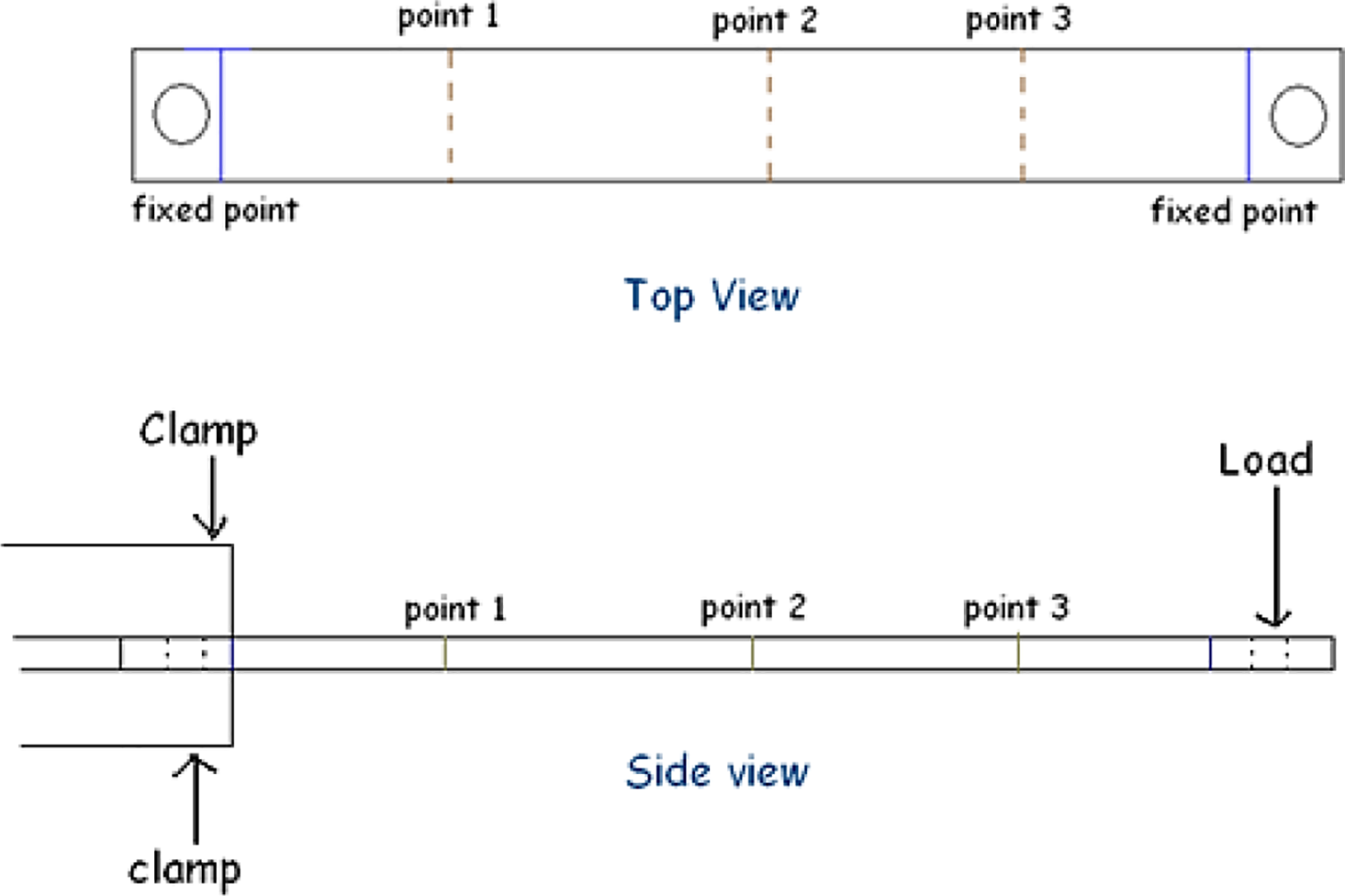
(a) and (b) Loading and measurement points in deflection tests.
Modeling of cantilever beam and finite element analysis of deflection
The arrangement of the cantilever beams is composed of two different materials, three different materials, and four different materials are shown in Figure 3(a) to (d). The general deflection formula for a cantilever beam given by equation (1) was used to derive the deflection equations for the various types of FGNF beams

(a) to (d) Illustrations of the beam arrangement used in various deflection tests.
where y is the deflection at any point x, E is the flexural modulus, I is the sectional area moment, and M is the moment applied. For an applied load P, the equations describing the general shape of the FGNF cantilever beam of length L for the homogeneous material, two different materials, and three different materials can be derived as follows

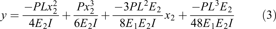

From the above equations, the expressions for the maximum deflection y max for a cantilever beam made up of a single homogeneous material, two different materials, three different materials, and four different materials are given, respectively, by


These 2D model equations give approximate predictions on how the composite beams deflect when the loads are applied. For more precise prediction, the 3D models of the cantilever beams of FGNF composites were created using SolidWorks software (2009). The structures were constructed in number of sections according to 40–30 composites, 40–30–20 composites, and 40–30–20–10 composites. The beams were modeled according to the dimensions of 145 mm length, 25 mm width, and 3 mm thickness. The analysis of displacement was carried out using CosmosWorks software (2009). Material library was created to input the corresponding property values for RPP-WSD composites of a different filler loading determined from tensile and three-point bending tests. Solid mesh study was used to analyze the displacement of cantilevered beam under static conditions. The procedure of analysis in CosmosWorks can be summarized as follows: Assign material with different properties to different sections accordingly. Define the system boundary condition, that is, location and magnitudes of restraints and force on the structure. Mesh the structure with the default global element size. The element size was decided based on the structure’s volume and surface area. Display the results of analysis of structural displacement. Using clipping feature find displacement values at point 1, point 2, and point 3.
Typical finite element results for the 40–50 FGNF composite are shown in Figure 4.

Finite element models of composite cantilever beam under static load.
Results and discussion
Functionally graded composite
Figure 5 shows a thin film layer of the FGNF composite consisting of different compositions of WSD loading and RPP composite. There was no bubble formed on the surface, which means there is no moisture trapped during the compression molding process. The distribution of filler content required to be controlled along the plate can be seen on film that formed due to excess flash during compression molding. From the observation, higher filler content section tends to be darker because the fillers are compacted in the space, while the lower filler content section tends to be transparent due to the light color of polypropylene. There is a boundary separating the different sections that can be seen on a thin film of the material. During the hot press, different compositions of sheet molding compounds were preheated and compressed. The matrix (polypropylene) at one section melted and mixed with the matrix at another section and the two were bonded together during the cold press. Meanwhile, during the process, the filler did not melt and bind together. The filler occupied the space and the distribution as they were arranged. The characteristic of boundary layers is dependent on how much space the filler occupied and the matrix binding across the layer. The WSD filler gave isotropic properties to the composite according to filler content at every section of the composite. This means that a section of 40% WSD loading has its own unique mechanical properties. The WSD filler has aspect ratios that make them resist the movement and realignment, thus improving the ductility of the composite. From the past research, the increase in WSD filler loading has increased flexural strength and modulus except at 40% filler loading. 14 Generally, the development of functionally graded concept of WSD filler-RPP composite has created a material that has high stiffness at sections that have high filler content and less stiffness at sections that have low filler content.

Functionally graded natural filler composite consisting of 40%, 30%, 20%, and 10% of WSD filler loading. FGNF: Functionally graded natural filler. WSD: waste wood sawdust.
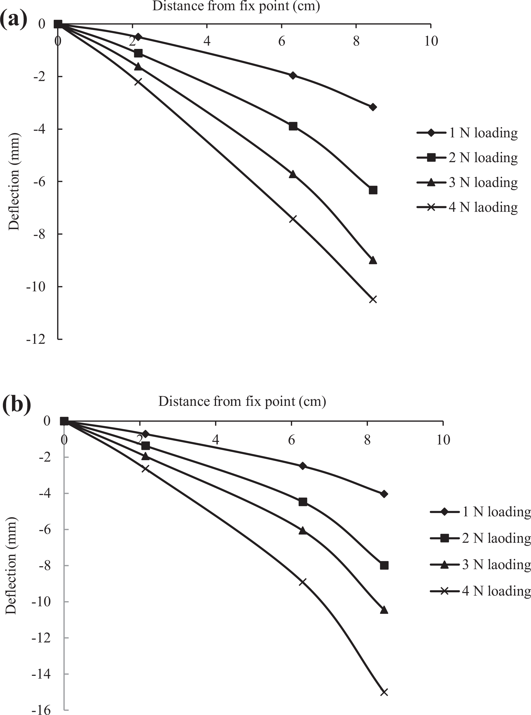
Deflection of cantilever beam: 40–30 and 30–40 FGNF composites
The results of deflection of the 40–30 and 30–40 FGNF composites at point 1, point 2, and point 3 with difference loading are shown in Figure 6(a) and (b), respectively. In each case, the beam was fixed at 9.4 mm from the edge. As expected, the deflection at any point along the beam increased as the loading increased. For the 40–30 beam, the highest deflection value recorded was 8.25 mm at point 3 when 4 N load was applied, while the lowest deflection value was 0.28 mm at point 1 with 1 N loading. For the 30–40 beam, the highest deflection value recorded was 10.95 mm at point 3 with 4 N loading, while the lowest deflection value recorded was 0.64 mm at point 1 with 1 N loading. Point 1 (3.1 cm from fixed point) has the lowest increment of deflection, while beyond point 2 (middle of the beam) the increment of deflection dramatically increases with load. The 40–30 beam shows smaller deflection over distance compared to the 30–40 setup. At point 3, the 40–30 beam has 32.7% lower deflection compared to the 30–40 beam. This is because 40% filler loading has higher flexural modulus (2.55 GPa) compared to the 30% filler loading (flexural modulus = 1.95 GP) resulting in lower deflection nearer to the fixed end.

Graph of defection of cantilever beam versus distance from fixed point for: (a) 40–30 FGNF composite and (b) for 30–40 FGNF composite beam. FGNF: Functionally graded natural filler.
Deflection of cantilever beam: 40–30–20 and 20–30–40 FGNF
Figure 7(a) and (b) shows the result of deflections of the 40–30–20 and 20–30–40 FGNF composite beams at point 1, point 2, and point 3 with difference loadings. In Figure 7(a), the beam was fixed at 9.4 mm from the edge of 40% filler loading section. The deflections increase as the load applied increased as expected. For the 40–30–20 beam, the maximum deflection recorded was 10.49 mm at point 3 at 4 N load. Meanwhile, for the 20–30–40 beam, the maximum deflection recorded was 15 mm at point 3 when 4 N load was applied. Fixing the beam close to the 20% composite section produced deflection value 43% higher compared to fixing at 40% section. Again, this is due to the lower flexural modulus of the 20% section compared to the 40% section.
Graph of defection of cantilever beam versus distance from fixed point for: (a) 40–30–20 FGNF composite and (b) for 20–30–40 FGNF composite. FGNF: Functionally graded natural filler.
Deflection of cantilever beam: 40–30–20–10 and 10–20–30–40 FGNF
Figure 8(a) and (b) shows the results of deflection of the 40–30–20–10 and 10–20–30–40 FGCM beams at point 1, point 2, and point 3 under difference loading. In Figure 8(a), the beam was fixed at 9.4 mm from the edge of 40% filler loading section. The maximum deflection recorded was 14 mm at point 3 when 4 N load was applied. Figure 8(b) shows the deflection results for the 20–30–40 arrangement. In this case, the beam was fixed at 9.4 mm from the edge of 10% filler loading section. The maximum deflection value recorded was 17.5 mm at point 3 when 4 N load was applied. The reversed arrangement in which beam is fixed at section of 10% filler loading shows higher value of deflection as expected due to the lower stiffness of the 10% filler loading section. In both cases, it can be visualized from Figure 8 that when there are four sections with different filler loadings the relationship between the deflection and the distance from the fixed edge is described by the complex third-degree polynomial function in equation (4).

Graph of defection of cantilever beam versus distance from fixed point for: (a) 40–30–20–10 FGNF composite and (b) for 10–20–30–40 FGNF composite. FGNF: Functionally graded natural filler.
Comparison of experiment and finite element analysis
Figure 9(a) and (b) shows the comparison between the experimental results and finite element analysis for the 40–30 beam when it is fixed at the 40% filler loading and 30% filler loading sections, respectively. The experimental (actual) and simulation results are reasonably close for both cases except at point 3 for the first case where a larger deviation could be seen. The differences could be due to the nonlinear behavior of the composite material during the actual experiment, whereas the finite element model assumes a linear model.
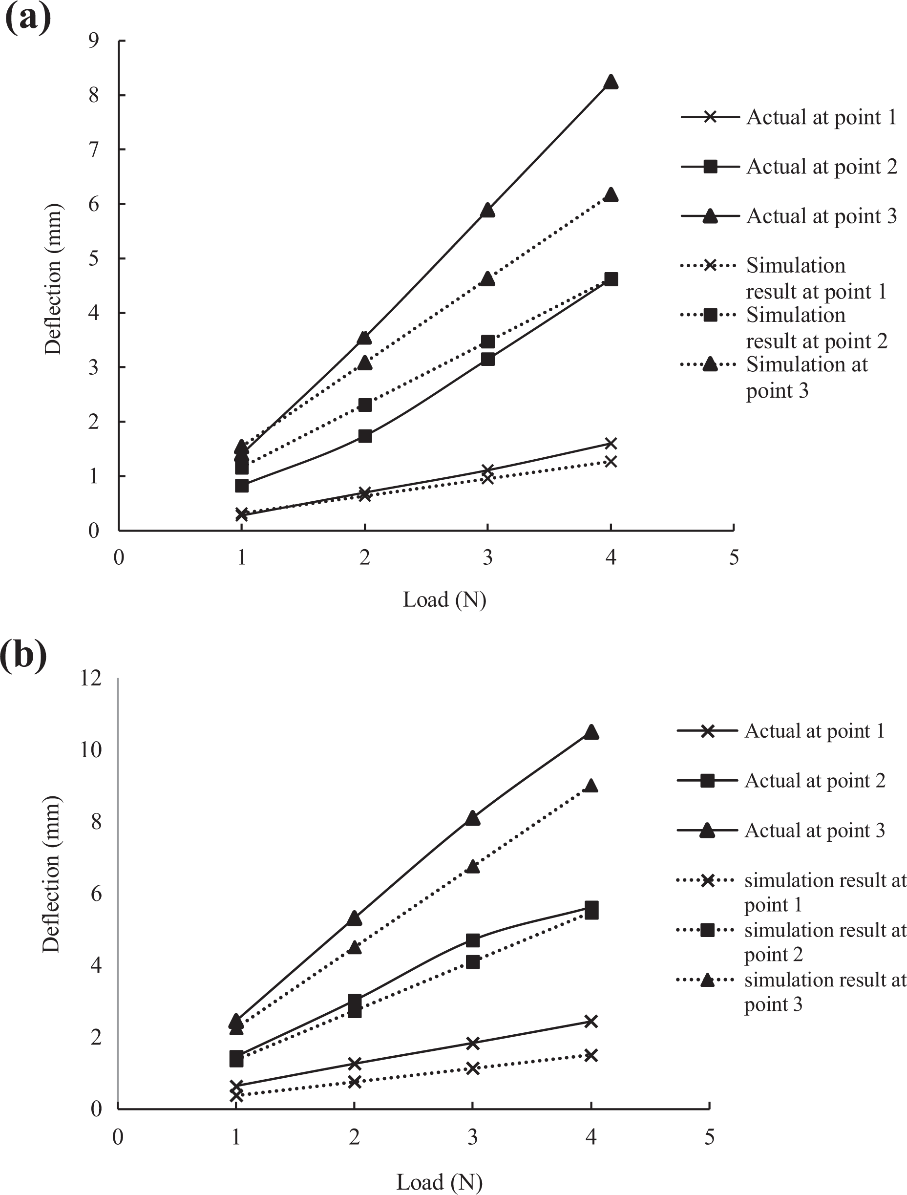
Graph of experimental (actual) and simulation result of 40–30 cantilever beam deflection: (a) when the beam is fixed at 40% filler loading section and (b) when the beam is fixed at 30% filler loading section.
Figure 10(a) and (b) shows the comparison between experimental and prediction of the finite element model for the 20–30–40 cantilever beam. In Figure 9(a), the beam was fixed at 9.4 mm from the edge of 40% filler loading section. The experimental and simulation results can be seen to agree very closely at measurement point 1 and point 2. When the beam was fixed at the 20% deflection, a larger deviation between the measurement and simulation results was observed at point 2 and point 3. The difference increased with load indicating the possible nonlinear effect in the beam at greater deflections. Similar observations were made on the 40–30–20–10 cantilever beams (Figure 11).

Graph of actual and simulation results of 40–30–20 cantilever beam deflections: (a) when the beam is fixed at 40% filler loading section and (b) when the beam is fixed at 20% filler loading section.

Graph of actual and simulation result for 40–30–20–10 cantilever beam deflections: (a) when the beam is fixed at 40% filler loading section and (b) when the beam is fixed at 10% filler loading section.
Comparison of deflections for different setups for fixed load
Figure 12 shows the deflections of the beams over distance from the fixed point between difference setups when 4 N loads was applied. The 10–20–30–40 setup shows the highest deflection compared to the other setups, while the 40–30 setup shows the least deflection. When there is a greater variation in compositions along the cantilever beam, the beam become less stiff due to the introduction of more low stiffness material into the beam. Material of lower stiffness (high flexural modulus) nearer to the fixed end produces lower overall deflection.

Comparison of deflections for different arrangements when 4 N loading was applied.
The results of the analysis show that the natural filler–polypropylene composite structure can be custom-made for specific application depending on the overall stiffness needed. In applications where larger deflection is desired, such as in snap-fit casings, the material can be designed with lower stiffness at the snap-fit joint and higher stiffness at other places. The deflection study shows the possibility of obtaining different deflections both using composites of different proportions and arrangement (setup) of the structure when used in actual application.
Conclusion
This study has shown that the FGNF-RPP composite structure can be custom-designed to obtain various types of deflection behavior under mechanical load. The deflection behavior can be predicted fairly accurately using finite element analysis. The defection is controlled by two factors, namely the number of gradations of the composite ratio along the structure and the section of the structure used as the fixed point. Lower deflection can be obtained using materials having higher flexural modulus and fixing the higher filler content section. High deflections can be obtained using a beam having larger number of gradations. By selectively designing sections along the composite structure with different mechanical properties, it is possible to design products where some sections need higher flexibility than others, such as products having snap fits.
Footnotes
Declaration of conflicting interests
The author(s) declared no potential conflicts of interest with respect to the research, authorship, and/or publication of this article.
Funding
The author(s) received no financial support for the research, authorship, and/or publication of this article.