
Abstract
Radial gap will occur at the spindle–tool holder interface when the spindle rotates at high speed. Therefore, the radial gap will lead to the nonlinear stiffness at the spindle–tool holder connection, and it will have effects on dynamic characteristic of spindle system. In this research, classic elastic theory is adopted to evaluate the nonlinear stiffness at spindle–tool holder interface. Dynamic model of spindle system is established considering the nonlinear stiffness at spindle–tool holder interface. The fourth-order Runge–Kutta method is applied to solve dynamic response of the spindle system. On that basis, effects of drawbar force on dynamic characteristic of the system are investigated. Considering the cutting force, effects of rotational speed on dynamic response of cutter tip are also discussed. The numerical results show that the drawbar force has effects on vibration mode of cutter tip. Chaotic motion will not occur within the range concerned in engineering practice. Considering the cutting force, the motion of cutter tip turns to be chaotic. The proper rotational speed and drawbar force should be chosen to ensure a stable cutting according to the response of cutter tip.
Introduction
With the development of high-speed machining (HSM), higher demand for the spindle in machine tools are proposed. The interface of spindle–tool holder is the weak link in the whole spindle system. In the high-speed situation, the stiffness of interface at spindle–tool holder will decrease due to the centrifugal force. Relative displacement between spindle and tool holder may even occur. The variation of stiffness can be ignored in low rotational speed, but it must be considered in HSM. 1 Many researchers focus on this issue. The method can be mainly divided into finite element (FE) method and experimental method. Xu et al. 2 established a FE model of spindle–tool holder joint subjected to clamping and centrifugal forces, and numerical identification of contact stiffness was also conducted. Agapiou 3 proposed a method for predicting the contact stiffness at spindle–tool holder interface based on two-dimensional FE analysis, and the method was validated by experimental results. Wang et al. 4 established a dynamic model of high-speed spindle system with spindle-bearing joint and spindle–tool holder–tool joints. The influence of speed and cutting force was investigated. Yoon and Shen 5 presented a numerical model predicting the shock response of a rotating-shaft spindle motor with nonlinear fluid dynamic bearings. Equations of motion were derived and numerically integrated to predict nonlinear shock response of the spindle. Gao et al. 6 studied the nonlinear response of a machine-tool spindle system supported by ball bearings by the three-term harmonic balance method and numerical method. The influences of the bearing contact stiffness and the eccentricity on the frequency response curves were studied, which presented some useful information to analyze and avoid the nonlinear response of spindle bearing system. Abeysuriya et al. 7 modeled sleep spindles using a corticothalamic neural field model of the brain. Nonlinearity in the thalamic relay nuclei that produced a spindle harmonic oscillation was discussed. Jia et al. 8 established a nonlinear dynamic model of the grinding motorized spindle system considering centrifugal force and bearing stiffness softening. Dynamic behavior was investigated, and the threshold of chaos motion of system was predicted. Cao et al. 9 built an integrated FE model with the nonlinear of bearing which has outer ring defects. The Newmark time integration method was used to solve the vibration responses numerically. Nam et al. 10 conducted the dynamical analysis and robust control synthesis for spindle machining system. A nonlinear model was established for the machine tool spindles. The phase portrait and bifurcation analyses were provided to show dynamical behaviors for spindle machining.
Hammering test is an effective method to identify contact stiffness at spindle–tool holder interfaces. Movahhedy and Gerami 11 established a dynamic model of spindle–tool holder including linear stiffness and bending stiffness of the joint. The optimization method was employed to identify dynamic parameters based on hammering test results. Özşahin et al. 12 identified the dynamic parameters of spindle bearing and tool–tool holder–spindle interface by impact testing at the stable situation. Apart from hammering test, Du and Hong 13 proposed an ultrasonic method to measure the contact stiffness and contact stress distribution at spindle–tool holder interface.
Some other methods are developed to predict dynamic parameters of spindle–tool holder interface. Budak et al. 14,15 established a dynamic model of spindle–holder–cutter system by receptance coupling substructure analysis method 16 –18 in their own research. Gao 19 and Liao 20 established a model for identifying the contact stiffness at spindle–tool holder interface based on fractal theory respectively. However, the contact stiffness at spindle–tool holder interface becomes nonlinear due to the high rotational speed and cutting force. Few research focused on it and discussed the influence on the dynamics of spindle system further. In this research, a nonlinear model for determining contact stiffness at spindle–tool holder is proposed based on the classic elasticity theory. On that basis, a nonlinear dynamic model of spindle system under cutting force, which takes into account the nonlinearity of spindle–tool holder stiffness and cutting force, is established. Effects of drawbar force and rotational speed on transient response of cutter tip are discussed.
Nonlinearity of the contact stiffness of spindle–tool holder
In high-speed rotation status, the radial gap will occur if the drawbar force is not great enough.
1
The radial gap will lead to the nonlinear relationship between radial relative force Fx
at spindle–tool holder interface and radial relative displacement
The spindle and tool holder are both made of high-quality steel. Therefore, they have the same material property. According to the classic elasticity theory,
21
for an annulus, with outside diameter b, inside diameter a, and thickness h (h << b and a), it can be modeled as a plane stress problem. When the annulus rotates around its center with the angular velocity

where E,
Cross-section sketch of a certain kind of spindle–tool holder is shown in Figure 1(a). The spindle and tool holder are axisymmetric. A three-dimensional Cartesian coordinate system 0xyz is established. The length of spindle–tool holder in −y direction is much more than other sizes. Therefore, the spindle–tool holder can be simplified as a plane strain problem. According to the relationship between plane stress problem and plane strain problem, E is substituted by

Spindle–tool holder: (a) sketch, (b) deformation.

where r 1 and r 2 are inside diameter and outside diameter of the hollow cylinder, respectively.
For the spindle and tool holder that are described in Figure 1(a), the radius of the interface whose y-coordinate is y can be expressed as r(y). r(y) can be obtained by linear interpolation with ri and ro . According to expression (2), radial displacements of nodes at the interface of spindle–tool holder can be expressed as: 10

where

The relationship among
The connection between spindle and tool holder is an interference fit. Contact stress at the interface under the action of drawbar force and cutting force is: 1

where
The equilibrium equation of tool holder in −y direction shown in Figure 1 can be drawn as follows:

where Fy
is the drawbar force; φ is the angle between the interface and y-axis. S represents the spindle–tool holder interface. When expression (5) is introduced into expression (6),
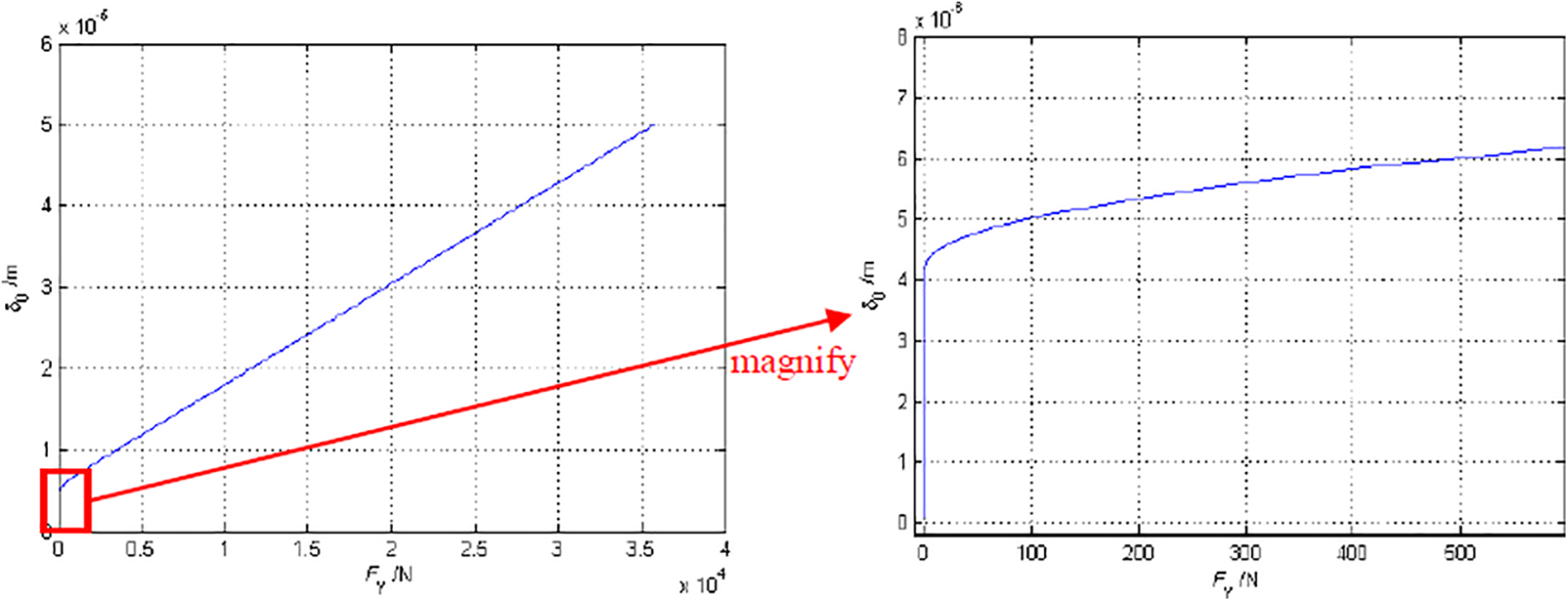
The relationship between
The interaction between the spindle and tool holder in −x direction (shown in Figure 1) Fx can be determined as:

Nonlinear dynamic model of the spindle-cutter coupling system
The schematic of a certain spindle-cutter system is shown in Figure 3. The rotor of spindle is held up by two pairs of angular contact ball bearings. To drive this spindle system, an integral induction motor is located between the front and rear bearings. As the vibration in normal direction of machining plane (−x direction shown in Figure 4) has effects on machining precision, vibration only in −x direction is concerned in this model. The spindle-cutter system is simplified to a five degree-of-freedom dynamic system as shown in Figure 4.

A schematic of the spindle-cutter coupling system.
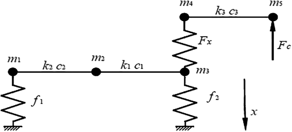
Nonlinear dynamic model of spindle-cutter coupling system.
Where m 1, m 2, and m 3 are discrete masses constituting the spindle; m 4 and m 5 are discrete masses constituting the milling cutter; f 1 and f 2 are support forces from bearings; Fx is the interaction in −x direction between the spindle and tool holder, which can be determined by the method in the second section; Fc is the radial cutting force; k 1 and k 2 are the stiffness of spindle; k 3 is the stiffness of milling cutter; c 1 and c 2 are material damping of spindle; c 3 is material damping of milling cutter.
In this research, the equivalent mass (
According to the second Newton’s law, dynamic differential equation of the spindle-cutter system is formulated as follows:

where x
1, x
2, x
3, x
4, and x
5 are displacements of nodes in −x direction corresponding to mass shown in Figure 4, and the downward direction is the positive direction. x
4–x
3 is equivalent to
The support force of angular contact bearing can be written as: 23
where z is the number of balls, D is the diameter of ball, F is the preload, and α is the contact angle of bearing.
Results and discussion
Dimensionless variables


The dimensionless equation of spindle-cutter system is a set of ordinary differential equations with nonlinear and nonsmooth excitation. For this equation, the analytical method to study nonlinear dynamic characteristic is difficult. The fourth-order Runge–Kutta method is adopted to solve equation (10). The relatively shorter time step is chosen to reduce the calculation error; meanwhile, a certain periods are abandoned to obtain stable transient solution of the system at the beginning of calculation.
24
In this research, the time step
Effects of drawbar force
To discuss the effect of drawbar force on nonlinear dynamic characteristic of the system, responses of cutter tip under different drawbar forces (i.e.
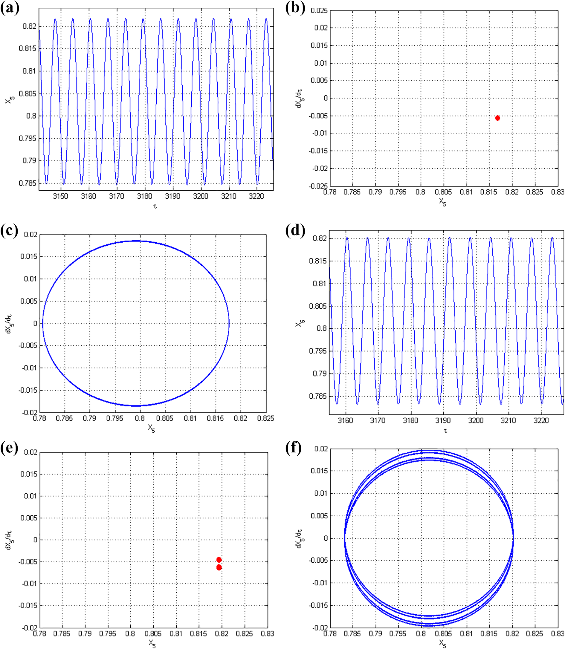
Comparison of responses of cutter tip under different drawbar forces: (a) time-domain response; (b) Poincare section; (c) phase trajectory,
The comparison highlights that Poincare section when
Effects of rotational speed
To investigate the vibration of cutter tip in cutting process, the cutting force must be considered. The transient cutting force is determined by the method described in the literature. 25 Through the comparison between the vibration with cutting force and that without cutting force, the conclusion can be drawn that the cutting force changes the vibration mode of cutter tip, and the vibration without cutting force is a periodic motion, whereas the vibration with cutting force turns to be chaotic.
To study the effect of rotational speed on nonlinear dynamic characteristic of the system, responses of cutter tip under different rotational speeds (i.e.

Responses of cutter tip under different rotational speeds: (a) time-domain response; (b) Poincare section; (c) phase trajectory,
According to the response described in Figure 6, each Poincare section has many disordered points. It is a chaotic motion. The nonlinearity of the contact stiffness of spindle–tool holder should be avoided to ensure a stable cutting. The contact stress at the interface under the action of drawbar force and cutting force should be positive according to expression (5). Therefore, expression (11) is satisfied.

By solving expression (11), the relationship of rotational speed and critical drawbar force is obtained as depicted in Figure 7. When the rotational speed is selected, the critical drawbar force is determined. The drawbar force Fy should be greater than the critical value.

Relationship of rotational speed and critical drawbar force.
Conclusions
A nonlinear model for determining contact stiffness at spindle–tool holder is proposed based on classic elasticity theory. On that basis, a nonlinear dynamic model of spindle system under cutting force, which takes into account the nonlinearity of spindle–tool holder stiffness and cutting force, is established. Effects of drawbar force and rotational speed on transient response of cutter tip are discussed. The results of the numerical simulations indicate that the drawbar force has effect on the vibration mode of cutter tip. When the cutting force is considered, the motion of cutter tip turns to be chaotic. The proper rotational speed and drawbar force should be chosen to ensure a stable cutting according to the response of cutter tip.
Large amount of calculation is conducted during the solution of equation (5). The next stage of the research is how to decrease the amount of calculation.
Footnotes
Acknowledgments
The authors would like to thank Prof. Chaozong Liu and Dr. Maryam Tamaddon from University College London for providing the facility to conduct the simulation.
Declaration of conflicting interests
The author(s) declared no potential conflicts of interest with respect to the research, authorship, and/or publication of this article.
Funding
The author(s) disclosed receipt of the following financial support for the research, authorship, and/or publication of this article: This research was funded by National Natural Science Foundation of China, grant number 51875008, 51505012, and 51575014; China Scholarship Council, grant number 201806545032; and basic financial support from Beijing Municipal Education Commission.