
Abstract
In this study, finite element modeling is performed to investigate the compressive failure of the composite sandwich structures with layered composite shells. An embedded debond area between the layered composite shell and the foam core is assumed as a defect. The composite shells are several plies of equal thickness Kevlar, carbon fiber composite, and E-glass composite with epoxy resin. Three different lay-ups, namely, (0°/90°/0°/90°/0°/90°), (45°/−45°/0°/90°/60°/−30°), and (60°/−30°/90°/0°/30°/90°) are considered for symmetric and asymmetric sequences. The work focuses on the importance of cohesive zone model versus the previously conducted numerical simulation and experimental results for buckling of sandwich composite structures. This enables one to account for delamination growth between shells and core and improve the correlation results with those of experiments. It has been shown that not only the cohesive model is capable of demonstrating delamination propagation, but it also correlates very well with the experimental data. By compiling user-defined cohesive mesoscale model in Abaqus simulation, the local and global buckling of the face-sheets can be precisely detected and response of sandwich structure becomes mesh independent, while mesh size is reduced.
Introduction
The increasing demand for composite materials due to their lightweight has led engineers and researchers to utilize them in several promising applications. Composite materials are designed in a way to achieve superior thermomechanical properties and strengths, which cannot be achieved using traditional materials. In particular, prepreg composites have many applications in aerospace and automotive fields. Although in-plane material properties of composite materials are high, their through the thickness strength is deficient due to not having any fiber reinforcement in the very direction. 1 Therefore, cracks in interlaminar direction, which is called interfacial delamination, could be initiated and grown. Delamination is the most common failure mode in composite materials and structures. It will avoid the structure to efficiently carry the loads and jeopardizes the stability of the composite parts and components. 2 Furthermore, material strength decreases significantly due to delamination. Hence, many experimental and numerical results related to the ultimate strength of debonded shells have been published. 3 –5 Several experimental tests on investigation of the flexural behavior of composite panels with delamination have been carried out. 6 –9 In addition, numerical techniques and parametric study 10 and the finite element (FE) analysis 11 –13 are also employed to investigate buckling behavior of reinforced sandwich composite beams and plates.
Fabrication or processing defects, impact of operational load, tool drops and intrusion of moisture are some of the reasons of delamination. In a very related article, the problem of delamination buckling has been addressed, emphasizing growth of the buckling load that leads to panel failure. Ji et al. 14,15 studied the buckling of a composite sandwich beam, panel, and strut using a planar classical elasticity method. Moreover, the progressive failure of a monolithic composite panel having an initial delamination were carried out considering both interactive out-of-plane and in-plane failure modes. 16
Predicting delamination and generated interlaminar stresses due to axial and shear stresses is a complex and difficult phenomenon. 17 The previous studies have brought attention to the fact that composite structures are failing by increased delamination area. Moreover, it is a critical damage in sandwich structures under compressive loads due to the difficulty in detecting delamination. 18,19 A nonlinear FE strategy was used by Kyoung et al. 20 to understand the effects of instability on cross-ply laminates with multiple type delamination. Hwang and Liu 21 investigated the effects of the non-linear buckling loads of different types of delamination. Wang and Zhang 22 studied the delamination growth in laminates with single and double delaminations numerically. The effects of multiple delaminations in a carbon/epoxy prepreg under different buckling loads were studied using FE analysis by Cappello and Tumino. 23 The critical buckling load and the associated mode shapes were influenced by the longitudinal asymmetry of delamination and delamination length. 24
Carlsson et al. 7,25 did numerical analyses along with experimental compression tests on of shell/core structures. They offered a sandwich structure using three-dimensional solid elements in the ANSYS for fiberglass/polyvinyl chloride (PVC) skin/core column and compared the numerical results to those of compressive tests which were on a set of sandwich structure with an artificial skin/core debond. The skin was modeled as multilayered isotropic material. Their FE analysis was not able to detect local buckling of the sandwich composite. To overcome this issue, Gaiotti et al. 6,26 developed two different material models, namely, orthotropic and isotropic models, which were utilized in the simulation of the skin. Their built-in ADINA model, combined three-dimensional solid elements with layered shell elements and was able to avoid shear locking effects and captured the local buckling. However, they did not address cohesive interfacial bonding between the skin and the core and delamination growth was neglected in their studies and therefore their multilayered orthotropic model was not able to correlate well with the experimental results. Therefore, an efficient FE model is needed to simulate the skin/core sandwich structure with a good correlation of actual experimental tests to predict progressive buckling failure more precisely.
Addressing delamination problems, cohesive zone model (CZM), executed FE codes by cohesive elements, is quite most common method to simulate the propagation of delamination in composite structures. 27 –31 CZM can be tailored into local and continuum approaches since it is grounded on fracture mechanics (Figure 1). The CZM sets up cohesive elements between matching nodes, representing elements with dissimilar materials or plies in the composite laminate. Cohesive elements can capture the crack initiation as well as the process of crack propagation. The main advantage of the current study here is the prediction of the delamination growth for different delamination types by the use of cohesive elements.
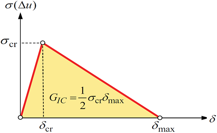
Traction-separation law. This figure can represent mode I, mode II, or mode III law. Note that the laws for each mode need not to be the same. 16
Liu et al. 32 numerically investigated the effect of cohesive law parameters including cohesive shape, strength, and element thickness within initial multiple delaminated composites subjected to a compressive force. Authors concluded that cohesive shape did not make a significant influence on the buckling load and the zero-thickness cohesive element was the best candidate for computational calculation and convergence.
The results of our newly developed model will ultimately be compared with those of the previous study 6 done for local and global buckling of skin/core composite structures with built-up FE model in ADINA. The results will also be compared with the experimental/numerical comparison of the tests reported by Vaddake and Carlsson 7 on debonded sandwich specimens. Once verified, several combinations of different materials for the sandwich core and the shells, lay-up sequences and fiber orientations are considered in the analysis with the cohesive element.
Geometry and modeling of structure
Before moving forward, our FE analysis methodology should be validated by correlation with previous numerical models and experimental results. Critical buckling loads were experimentally obtained by Vaddake and Carlsson, 7 showing the specimens going under local buckling with large deflections forcing skin delamination and consequently leading to the failure of the core of the specimen (see Figure 2). The model is clamped on both edges to simulate the experimental tests, and only the remaining free part of the specimen is simulated. Figure 3 shows the face/core structure and the delamination zone along with parameters a, b, and d which are 100, 50, and 38 mm, respectively. The reinforced structure is modeled for perfect (no separation) and also an implemented separation/debonding in one side of the composite between the core and the composite skin as shown.
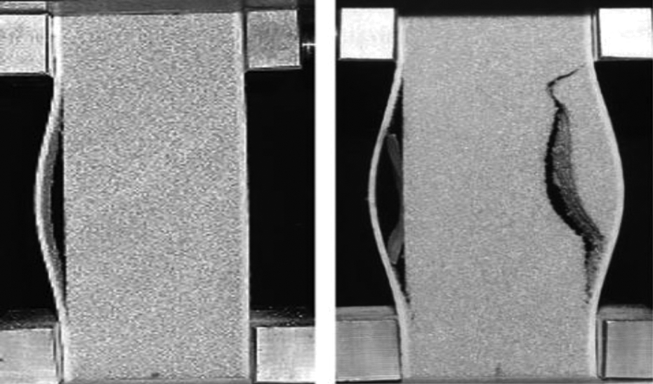
(a and b) Experimental tests photo, local buckling has a significant role in the progressive failure of the structure. 7

Geometry of the models for the reinforced sandwich structure for (a) reinforced perfect structure and (b) reinforced structure with embedded delamination.
Two sets of PVC cores 33,34 as presented in Table 1 along with three sets of reinforcing layered composite shells made of Kevlar/epoxy, carbon fiber composite (CFC)/epoxy and E-glass/epoxy as presented in Table 2 were used.


CFC: carbon fiber composite.
Gaiotti and Rizzo 6 primarily calculated the governing equations of stress and strain tensors. Matrices [N] and [M] are the overall resultant force and moment, which is generally expressed as in equation (1)

where [A], [B], and [D] matrices are the elements of the laminate stiffness matrix. Laminate forces [N] per unit width and laminate resultant moments [M] per unit width are attributed to the laminate mid-plane strains [ε 0] and laminate mid-plane curvatures [k] through the stiffness matrix. Matrix [A] relates the resultant forces to the strains and matrix [D] relates the resultant bending moments to the panel curvature. Matrix [B] couples the force and moment terms to the strain and curvature in midplane.

where
FE analysis
When buckling phenomenon occurs, delamination rapidly propagates. Delamination and its growth will definitely result in buckling load drop. The delamination growth and its effect on buckling load in sandwich structures by the use of cohesive elements will be investigated in this study. The main advantage of CZM over the classical models such as virtual crack closure technique is that there is no need for an initial crack to be embedded in the laminate. So in this section, we initially validate CZM approach with previous studies and subsequently present a number of different combinations of the materials for the face/shell and core, ply orientation, and symmetric/asymmetric sequences. Finally, we investigate buckling load capacity of two sandwich structures with and without delamination growth compared to a perfect structure (no delamination). Three major simulations will be carried out for a perfect shell/core sandwich structure, a sandwich structure with the embedded delamination with and without consideration of progressive delamination, respectively. It is expected that the use of cohesive elements improves the simulation quality, while the structure is under compressive loading. The schematic representation of the structure with embedded separation is demonstrated in Figure 4. Composite skin shells are connected to the sides of the core, with one side having an embedded debond.

Geometry model for reinforced structure with embedded delamination and cohesive elements.
A single layer of cohesive elements is used to represent the cohesive zone. The isotropic properties of the adhesive material with a given thickness is used to represent the cohesive zone. In case of a thin layer cohesive zone, it makes more sense to consider the interaction of the traction with separation. This requires the determination of the stiffness, strength, and fracture toughness properties. FE model of each structure is developed using the material properties of cohesive elements that are provided in Table 3. A high initial penalty stiffness is assumed to ensure a reasonable precrack behavior. 35 All specimens are unidirectional, and the fibers are aligned along the direction of the fracture propagation.
Material properties of the cohesive element. 34

The CZM technically announces a length scale parameter due to the softening behavior. Lack of a valid length scale in the analysis results in pathological meshing and subsequently an inaccurate fracture energy value. 32,36 So from the extensive previous literature on the analysis of cohesive zone, length scale for cohesive zones is predicted within a factor of 2–3 that is not far from unity. 36 –40
Maximum element size (solid element) representing the material on either side of the crack must be less than cohesive zone length to ensure mesh-independency near zones. Thus, to avoid iterative work which seeks mesh convergence, the length of the cohesive zones should be estimated a priori. According to Bao’s study, 36 for a delamination crack in a relatively slender body, the characteristic length is going to be estimated through becomes a material/structure property. The length scale of cohesive zone size and crack length can be calculated as 36

where Ep
, σ, and Gc
are elastic modulus, peak stress, and critical energy release rate, respectively. Furthermore, h is the half thickness of the sub-laminate (a conservative approach to get the most refined mesh would be recommended with the full thickness of the sub-laminate). Using the values in Table 3 and by equation (3), the crack length and cohesive zone length are calculated a = 26 mm and
As shown in the previous studies, 32,40 finite thickness cohesive element is not capable of predicting the crack propagation correctly. So the CZM is executed using zero-thickness cohesive element which addresses both the computational efficiency and numerical convergence. Large deformation analysis is included in Abaqus. As Liu et al. 32 investigated the effect of different types of CZM on the convergence, the exponential CZM showed the stronger convergence; thus, we utilized exponential CZM.
The generic FE model is depicted in Figure 5. The core elements are modeled using block elements (C3D8R). As for the composite layers, 8-node shells with reduced integration (S8R) is employed. Finally, to simulate and predict the separation growth, cohesive elements (COH3D8) are placed at the interface between face/shell and core to constrain their displacements. The cohesive elements are defined such that their stiffness degrades gradually during delamination. Technically, there is no tie in the debonded area, but there is cohesive element on all the intact surfaces. Regarding the boundary condition, the shell side with debond area was clamped on both edges to mimic the experimental test conditions 7 (see Figure 5). To represent the experimental test conditions, axial compressive displacements are applied longitudinally, and all the other translational degree of freedom are constrained.

Use of the cohesive model for the skin/core debond.
Figure 6 shows the orientation composite laminate shells for both symmetric and asymmetric sequences. Special attention needs to be given to attribute the skin composite shells to three-dimensional elements representing the core. Six different laminate lay-up each consisting of 12 plies of [0°/90°/0°/90°/0°/90°], [45°/−45°/0°/90°/60°/−30°], and [60°/−30°/90°/0°/30°/90°] for both symmetric and asymmetric laminates were used in the present study (see Figures 7 and 8.)
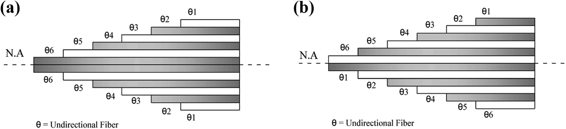
Schematic representation of (a) symmetric and (b) asymmetric sequences in layered composite shells.

Symmetric sequence: (a) [0°/90°/0°/90°/0°/90°], (b) [45°/−45°/0°/90°/60°/−30°], and (c) [60°/−30°/90°/0°/30°/90°].

Asymmetric sequence: (a) [0°/90°/0°/90°/0°/90°], (b) [45°/−45°/0°/90°/60°/−30°], and (c) [60°/−30°/90°/0°/30°/90°].
Results and discussion
Validation and comparison with previous works
Vaddake and Carlsson conducted buckling tests on sandwich core columns having an initial debond. 7 To do a validation and correlation with the previous experimental and numerical studies, 6,7 the six S2-fiberglass/vinylester [0/90] layers of the skin laminates are considered in the Abaqus simulation. Figure 9 shows out-of-plane deflection versus load for H45 coupons with a 50 mm initial debond. A cohesive model has been used for measuring lateral deflection of the debonded area. As it can be seen, CZM when compared to experimental measurements is successfully capable of predicting the debond propagation. According to the experimental reference, 7 we assumed a mesh size of 0.5 mm and a good convergence with a 5% error is obtained. In addition, another comparison study will be carried out with previous numerical models 6,2 5 for in-plane displacement of sandwich specimens.
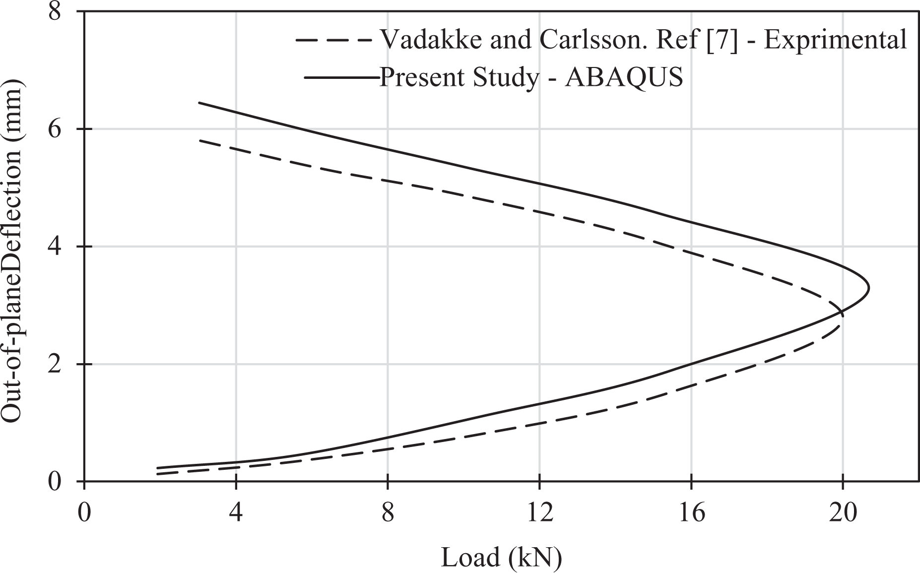
Out-of-plane deflection versus load for H45 coupons having a 50 mm initial debond.
Figure 10 shows a comparison of the load versus in-plane displacement for CZM approach used here with previously developed FE modeling strategies. As it can be seen, in the absence of progressive failure, Abaqus simulation is precisely correlating with FE built-in modeling in ADINA. 6 The model validated with reference 7 is implemented with new changes on the skin layers.
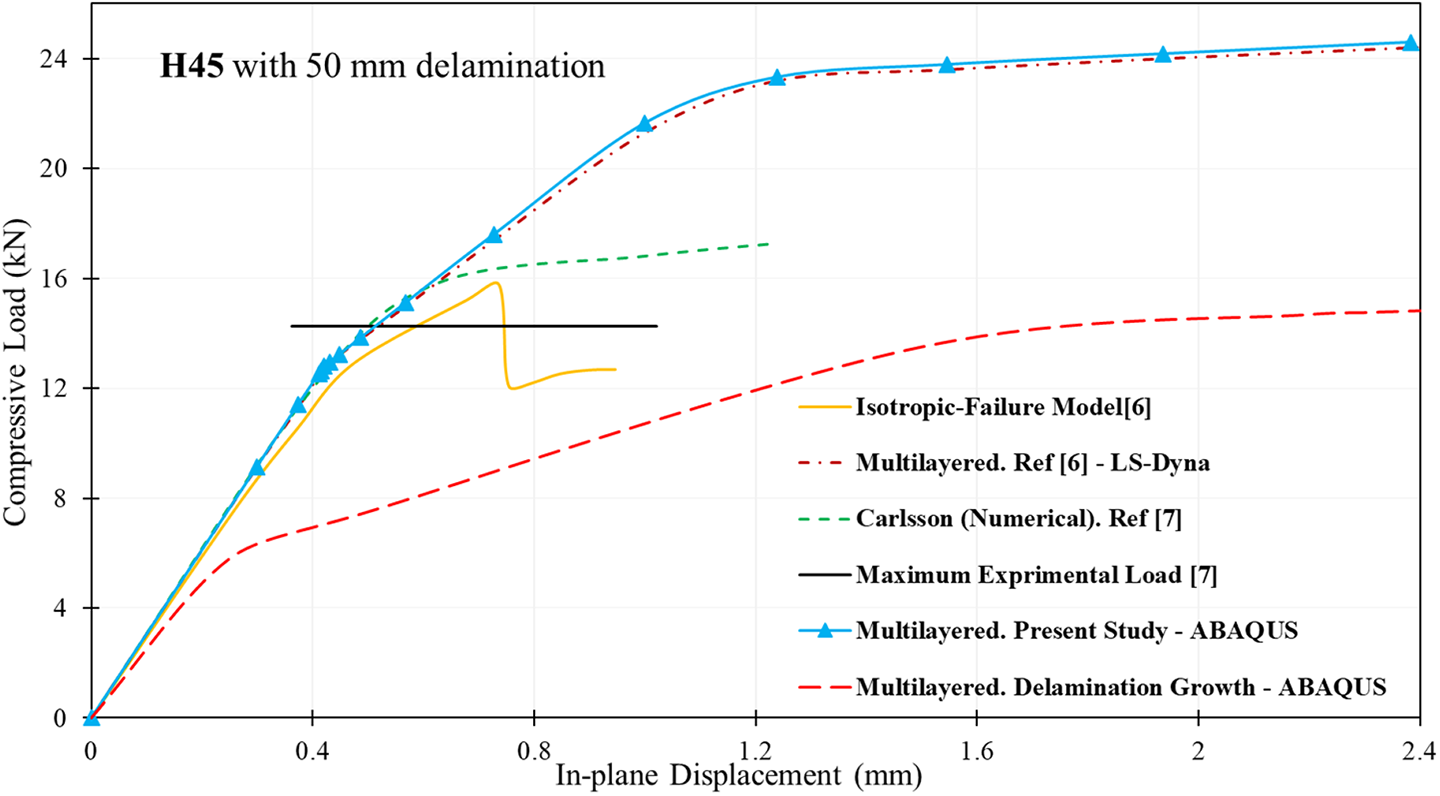
Comparison of different FE models and the experimental threshold with present study. FE: finite element.
All numerical models show a quite similar ultimate failure load except for multilayered models. In these models, while delamination growth is not considered, global buckling load is being achieved in higher values than experimental threshold. Although isotropic models seemingly meet the experimental threshold, it is not a reasonable assumption for the simulation of stacking lay-up shell. On the other hand, it can be seen that the delamination growth can be well predicted using the proposed cohesive model approach. They are perfectly able to capture the initial slope (i.e. linear portion) and the local buckling at the early stages. Inside of sandwich structures, there is always an adhesive layer placed between the skin and the core. This interface plays an important role in the failure development of composite structures. Once delamination propagates from the debond zone, cohesive elements are gradually degraded and finally removed. Interfacial degradation decreases the load-carrying capacity and consequently local buckling is observed at lower load magnitudes.
Mesh independency of CZM
Key incentive of this section is to investigate the mesh dependency of cohesive element (model) when crack propagation is simulated. Results discussed here are mainly based on a mesh density of H80–CFC (0/90/0/90/0/90) s structure and represent the load–displacement response as crack grows. Hence, variational multiscale cohesive method (VMCM), as a rigorous mesoscale method for simulating the crack growth, has been benefited from the work done by Rudraraju et al. 41 and implemented to capture a displacement discontinuity field. The cohesive model has been enriched by the help of shape functions and representing its capability in simulation of fiber-reinforced composites. In this method, some micromechanical constitutive equations were derived 41 and addressed for the enhancement of FE framework and code implementation. The equations, which were earlier elaborated for mesomechanical surface traction relation in, 41 are given below as

where
To prevent the distortion of the elements, the finer size of mesh might be helpful. VMCM has shown its capability to overcome the distortion problem while finer mesh is applied. Thus, all simulations here are carried out in a user-defined material model in Fortran and compiled in Abaqus. We primarily investigate crack propagation of two cases of composite structure under the symmetrically and asymmetrically (eccentrically) loading. Later in this section, element deletion is going to be investigated to predict how deep crack goes through.
Regarding mesh dependency, we first simulate the crack path for elements with above three orders of magnitude difference in density. Figure 11(a) shows the different mesh densities and types when load is applied symmetrically at the reference point. As shown in Figure 11(b), all the load–deflection responses are fully extended over each other. Hence, mesh does not show sickness behavior (pathological dependency) when load is applied symmetrically.

Mesh dependency for conventional crack propagation H80-CFC (0/90/0/90/0/90) s under symmetrical loading: (a) shell deflection contours for different mesh types and densities and (b) out-of-plane deflection–load response. CFC: carbon fiber composite.
To demonstrate mesh objectivity (dependency) under eccentrically loaded, two different case scenarios have been gone through. The eccentric loads are applied closer and farther to the debonded area in coordinates of (−10, 0, 0) and (+10, 0, 0) with respect to the reference point, respectively shown in Figure 12(a) to (d). Due to eccentric loading, the crack propagates with different speed in respect to symmetrical loading. It can be easily seen when the eccentric loading approaches the delamination area (left side), Figure 12(a) and (c), the shell is prone to buckle faster and consequently has more magnitude of deflection. On the other side, more carrying-load has been observed, yet less deflection, Figure 12(b) and (d). As to mesh dependency, a small variation in the deflection response may trigger a high mesh sensitivity. However, the resolution of the high stress gradients (buckling or unstable postbuckling response) depends to some extend on the element dimension and material nonlinearity and this naturally affects the buckling response of structures. Thus, all three case scenarios demonstrated below shows that VMCM method has no sickness in mesh refinement.

Mesh dependency for conventional crack propagation H80–CFC (0/90/0/90/0/90) s under eccentrically loading (a) shell deflection contours for different mesh types and densities at (−10, 0, 0), (b) shell deflection contours for different mesh types and densities at (+10, 0, 0), (c) corresponding out-of-plane deflection–load response at (−10, 0, 0), and (d) out-of-plane deflection–load response at (+10, 0, 0). CFC: carbon fiber composite.

Next, a case study on element deletion has been prepared by multiscale FE delamination of interfacial cohesive layer of H80–CFC (0/90/0/90/0/90)s and is depicted in Figure 13(a) to (f). As it can be seen, once the load is applied, cohesive elements start stretching until failure (i.e. scalar stiffness degradation parameter, 0 < D < 1, reaches 1) and subsequently eliminated. The deletion of elements initiates with the occurrence of the local buckling and continues until the structure reaches its global buckling. From the moment that local bucking occurs (see Figure 13(b)) all the way to the global buckling (see Figure 13(f)), 134 cohesive elements are eliminated which corresponds to a 10-mm element degradation zone. As delamination further progresses, the proposed multiscale approach shows further elimination of elements which eventually leads to the failure of the structure.

(a to f) Multiscale shape of a composite sandwich column representing interfacial damage by the use of cohesive elements.
Local and global buckling for structures with embedded delamination and delamination growth
Regarding the previous observation, FE analysis showed that CZM is a good predictor of delamination growth. In this section, buckling analysis of the face/core composite structures made of the epoxy CFC, the epoxy EGC, and the epoxy Kevlar composite with several combinations of the cores and the layup sequences, are presented in three different structures, namely, perfect with no delamination, structure with delamination, and finally structure with delamination growth. Figure 14 displays traditional Tsai–Wu criterion failure which is obtained from the FE model for the deformation of structure with reinforcing shells under compressive loading. This figure presents the buckling phenomena in a perfect structure with no delamination and a structure with an embedded delamination. The first mode shape is presenting the “local buckling” as it only affects a portion of the structure and occurs at 46.2 kN. When the applied load reaches 65.7 kN, global buckling occurs which shows 43% reduction in compared to that of the perfect structure occurring at 80.3 kN.

Tsai–Wu failure criteria for (0°/90°/0°/90°/0°/90°) symmetric H45 Kevlar/epoxy (a) global buckling for perfect structure, (b) local buckling, and (c) global buckling for structure with embedded delamination.
Figure 15 shows the implementation of the cohesive elements to represent instability of the structure with delamination growth under bucking load. The critical load-carrying capability is dropped by 65% and 52% to 28.3 and 38.3 kN, for the local and global buckling, respectively. The effects of separation, orientation, and laminate lay-ups with symmetric and asymmetric sequences on the stability behavior of reinforced structures with composite shells under compressive loading were also studied.

Tsai–Wu failure criteria for (0°/90°/0°/90°/0°/90°) symmetric H45 Kevlar/epoxy. Separation of cohesive element in structure with delamination (a) local and (b) global buckling for structure with delamination growth.
Most in-use reinforcing layered composite shells are being made in the form of symmetrical lay-ups, asymmetric lay-ups can be designed and manufactured to achieve complex industrial needs. Accordingly, the applied load has been investigated in symmetric and asymmetric composite shells for structure with delamination and delamination growth. Figure 16(a) displays a reinforced structure with Kevlar/epoxy-layered composite shells, and it shows the effect of the delamination for symmetric and asymmetric sequences. Subsequently, a reinforced structure with Kevlar/Epoxy-H45 shell with delamination growth has been investigated for different sequences in Figure 16(b). It can be evidently seen how the delamination growth plays significant role in decreasing the compressive load-carrying capacity. Considering the properties and mechanical behavior of the reinforcing shells, this numerical analysis indicates that the local buckling force is initially linear and starts showing a nonlinear behavior when they start failing. The stiffness of the structure which is tied to the slope of the curve suddenly drops which can be interpreted as a sign for global buckling occurring which consequently cause the whole structure to fail.

Applied compressive load for structure with Kevlar/epoxy and H45 core for symmetric and asymmetric sequences (a) with delamination and (b) with delamination growth.
Load versus transverse deflection is illustrated in Figure 17 for both structures with delamination and delamination growth. Figure 17(a) shows the variation of the applied load versus transverse deflection for [0°/90°/0°/90°/0°/90°] s Kevlar/H-45 laminate while there is no delamination growth. As it can be seen, local and global buckling occur at about 46 and 52 kN, respectively. Load-carrying rate then goes to plateau after global buckling and the structure cannot stand any higher loads. On the other hand, while there is delamination growth, as displayed in Figure 17(b), the laminate buckling load will be very small and happens in the early stages of loading for [0°/90°/0°/90°/0°/90°] s lay-up, then, the local buckling of the upper layers initiates and delamination gradually propagates. By increasing the load, the structure starts to locally buckle and the laminate deflects inward. This phenomenon arises from the debonded area between the shell and the core where cohesive elements are not utilized and therefore the skin is able to slightly deflect inward. After this slight inward deflection, the skin deflects outward and global buckling takes place at about 18 kN.

Load versus deflection for (a) structure with delamination and (b) structure with delamination growth.
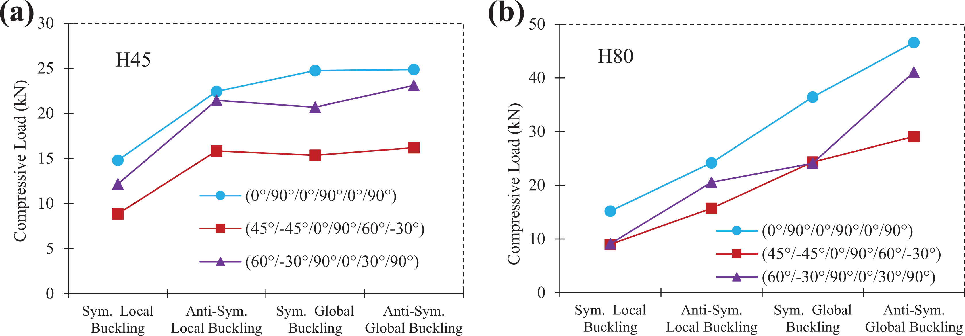
Moreover, Figures 18 to 20 show the effects of separation and laminate plies in symmetric and asymmetric sequences for other composite structure with different composite skins and cores. Although usually most of the designed composite laminates are symmetric, asymmetric lay-up sequences are occasionally used to design specific complex structures for a variety of uses. For all specimens, simulation was performed for layered composite shells for both symmetric and asymmetric sequences and with both H45 and H80 cores.

Compressive load of structure with delamination for (a) H45, (b) H80 cores and CFC/epoxy shells. CFC: carbon fiber composite.

Compressive load of structure with delamination for (a) H45, (b) H80 cores and E-glass/epoxy shells.

Compressive load of structure with delamination for (a) H45, (b) H80 cores and Kevlar/epoxy shells.
As it can be seen in Figure 18, the bending strength of structures with CFC/epoxy in the asymmetric sequence is much higher than that of structures with symmetric sequence for different layered composite shells and cores. Similar trends can be seen for the compressive strength of E-glass/epoxy and Kevlar/epoxy (see Figures 19 and 20).
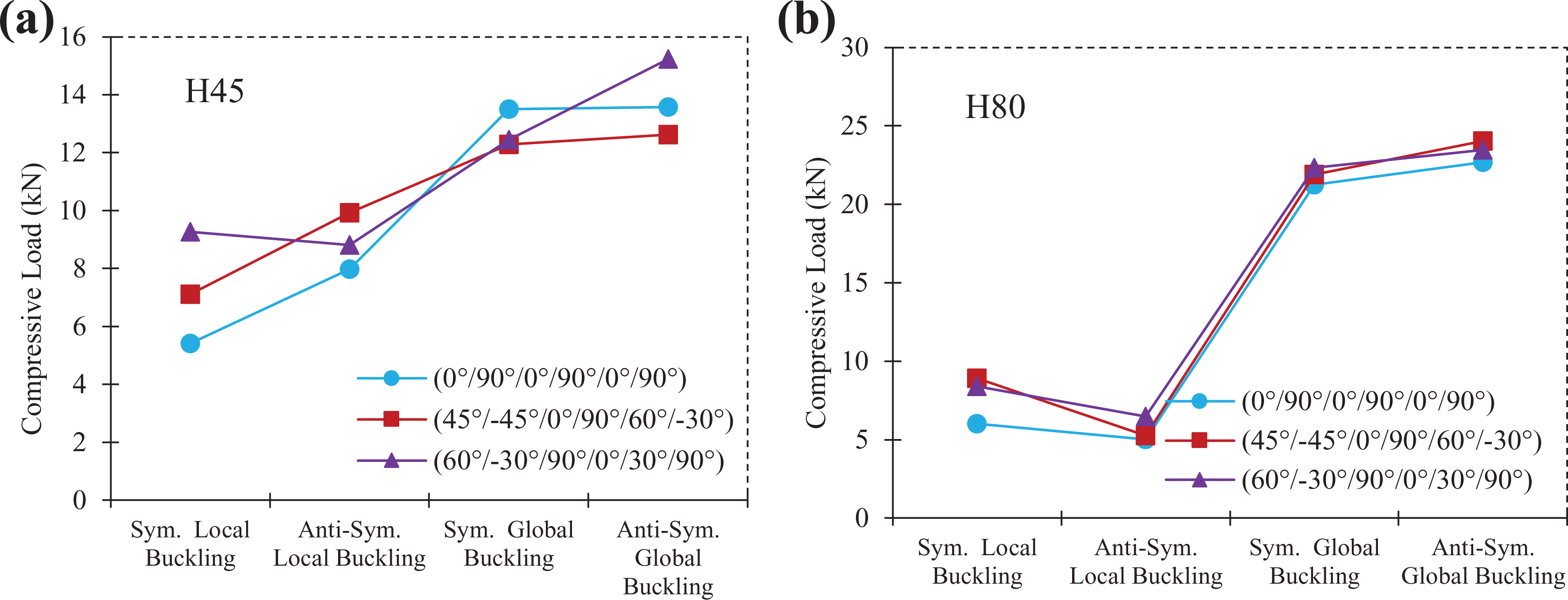
Similar plots have been provided for buckling of structures with a delamination growth in Figures 21 to 23. These results are in a close similarity with the previous results obtained, while there was no progressive delamination. However, the magnitudes of the buckling load in the existence of a delamination growth are significantly lower compared to a structure not having progressive delamination.
Compressive load of structure with delamination growth for (a) H45, (b) H80 cores and CFC/epoxy shells. CFC: carbon fiber composite.
Compressive load of structure with delamination growth for (a) H45, (b) H80 cores and E-glass/epoxy shell.

Compressive load of structure with delamination growth for (a) H45, (b) H80 cores and Kevlar/epoxy shells.
Thermo-mechanical case study for asymmetric laminate
Lately, several studies have been conducted on thermo-mechanical behavior of asymmetric sandwich composite structures under buckling loading. 42 –49 It is known that symmetrical lay-ups are required to avoid thermal deformations during the cure. Contrarily, when an asymmetric structure is manufactured (face sheets not symmetric) then at the manufacturing stage, there will be thermal residual stresses. This is because when heating the plies of the composite due to mismatch in coefficient of thermal expansion (CTEs) between the different materials within the composite layers, they expand differently with asymmetrical layup and give excessive thermal stress. Therefore, the objective is to show the results for the cases of including and excluding the thermal stresses.
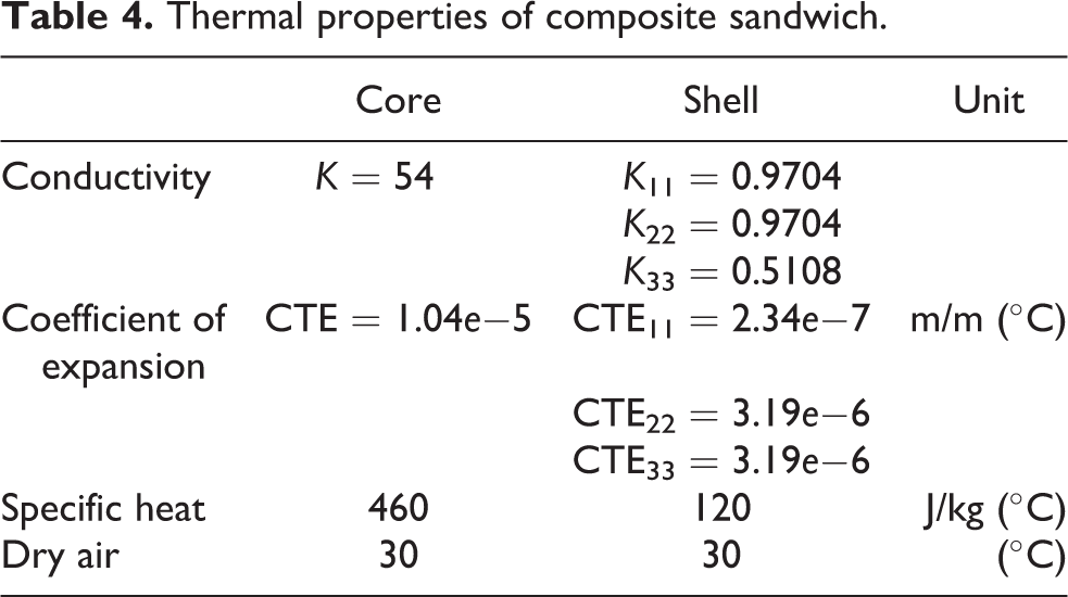
Regarding thermo-mechanical analysis, we need to have some information about core and face sheet which are given in Table 4. Similar boundary conditions are considered in thermo-mechanical analysis. Kevlar/H45 [0°/90°/0°/90°/0°/90°] is chosen for analysis as it shows better compressive behavior. This section is aimed to study the effect of thermal properties on the instability of asymmetric laminates in the presence of delamination. As shown in Figure 24, the thermal effects become noticeable once local buckling occurs; however, their contributions remain relatively low even after the occurrence of global buckling.

Effect of thermo-mechanical behavior of asymmetric laminate.
Thermal properties of composite sandwich.
Normalized buckling loads for structure with embedded delamination
Magnitudes of applied critical load in structure with delamination and delamination growth are normalized to perfect structure and shown by bar diagrams in Figures 25 and 26. These data are based on the results obtained from the numerical analysis in FE method simulations. They show that the normalized applied load decreases as a result of delamination, symmetric, and asymmetric sequences in layered composite shells.

Normalized buckling loads for structure with delamination compared to perfect structure.
Thus, the effects of symmetric and asymmetric sequences differ in terms of structures according to the properties and material behavior and therefore for every layered composite shell, a particular sequence is better than the others. These results provide an interesting correlation between the simulation and layup design.
Figures 25 and 26 demonstrate the normalized buckling loads for both structures with delamination and delamination growth compared to the perfect structure, respectively. Furthermore, the percentage of the load drop with respect to perfect structure is provided in Tables 5 and 6. As it can be seen, Kevlar fiber, with orientations (60°/−30°/90°/0°/30°/90°) and (0°/90°/0°/90°/0°/90°) and for asymmetric design is demonstrating the highest compressive strength among all the varied available designs. For instance, for Kevlar-H45 with embedded delamination and for symmetric and asymmetric sequences (60°/−30°/90°/0°/30°/90°), the knock down in the applied load-carrying capability is 11.7% and 10.4%, respectively. By changing the core density to Kevlar-H80 with embedded delamination for symmetric and asymmetric sequences (60°/−30°/90°/0°/30°/90°), the knock down in the applied load carrying capability is 17.3% and 15.3%, respectively. The load-carrying capability drops drastically in the existence of the delamination growth. Cohesive elements also display weaker bonding and consequently a greater amount of delamination propagation for H45. This leads to an earlier onset of damage and rapid propagation in the presence of the delamination growth.

Normalized buckling loads for structure with delamination growth compared to perfect structure.
Load knockdown percentage for the structure with the delamination versus the perfect structure.

CFC: carbon fiber composite.
Load knockdown percentage for the structure with the delamination growth versus the perfect structure.

CFC: carbon fiber composite.
Conclusion
Delamination is a crucial defect that needs to be carefully accounted for in the design and manufacturing of sandwich structures. Therefore, a number of combinations of the materials for the face/shell and core, ply orientation, and symmetric/asymmetric sequences on the buckling behavior of reinforced structures with layered composite shells under compressive loading were addressed in this study. FE simulations were validated against the previously obtained experimental buckling test results and numerical FE studies.
Several 12-ply layered composite shells were considered with Kevlar/epoxy, CFC/epoxy, and E-glass/epoxy combinations. Among all different combinations, Kevlar laminates with (60°/−30°/90°/0°/30°/90°) and (0°/90°/0°/90°/0°/90°) asymmetric designs were capable of presenting the highest axial compressive strength among all. It was shown that changes in core density could affect the compressive strength of the structure. For Kevlar with (45°/−45°/0°/90°/60°/−30°)as, and in the absence of delamination the load-carrying capability dropped 14.5% and 21.0% for H45 and H80, respectively. In the presence of delamination propagation, the drop in the applied load was increased to 66.2% and 55.1% for H45 and H80, respectively. It was observed that the compressive strength drop is ranged 10–30% when accounting for delamination/debond with no growth and 40–60% with growth. For each of the layered composite skin laminate, a particular sequence exhibited the optimum compressive strength. Thermal effects on manufacturing was also investigated and results became noticeable once local buckling occurred; however, their contributions kept on relatively low even after the occurrence of global buckling.
CZM was able to predict better the responses of the structure to the compressive loads. The crack length and cohesive zone length were calculated a = 26 mm and lcz ≅ 5, respectively. It was seen that delamination growth load falls within the local and global instability loads. Furthermore, as delamination grows alongside the interfacial bonding of the sandwich composite, the critical delamination growth load approaches that of the global buckling. Multiscale approach was shown to be a useful tool in progressive damage simulation without showing any mesh dependency, not only under response of symmetric but also under eccentrically loaded case studies. Cohesive layer was also able to estimate the length of propagation by the elimination number of cohesive elements from local buckling to the final failure. The main advantage of CZM is that delamination is robustly modeled and accounted for by simply removing the coupling between the elements confined by the face-sheet and the core.
Footnotes
Declaration of conflicting interests
The author(s) declared no potential conflicts of interest with respect to the research, authorship, and/or publication of this article.
Funding
The author(s) received no financial support for the research, authorship, and/or publication of this article.