
Abstract
The 3-D layer-to-layer angle-interlock woven fabric (LLAIWF) has good deformability on a complicated contour, which offers them a large application potential in the field of aerospace. This article mainly focuses on the influence of yarn fineness and number of yarn layers on in-plane shear properties of 3-D LLAIWF during bias extension. Two methods of varying the thickness of 3-D LLAIWF were designed: changing yarn fineness and changing the number of yarn layers. The deformation mechanism of LLAIWF in bias-extension test was analyzed. The effects of two methods on in-plane shear deformation were compared and analyzed. In addition to the data processing on the experimental curve, digital image correlation analysis was conducted on the test photographs, from which shear angles in different area shear angle were measured. The mesostructure of fabric during the bias-extension test was observed. The effect of decreasing yarn layers on the mesostructure of fabric was observed by cutting fabric. The results demonstrated that the yarn fineness and the number of yarn layers play a key role in the in-plane shear properties of 3-D LLAIWF. In addition, the changing of fabric thickness causes that the deformation is asymmetrical. The effect of warp yarn fineness is similar to that of weft yarn fineness during the bias-extension test. Reducing the internal yarns of the fabric created a gap, where the yarns were reduced. This gap will affect the deformability of the fabric.
Introduction
3-D woven fabric
The 3-D woven structural composites are currently being used in structural engineering applications due to their excellent through-thickness strength, outstanding damage tolerance, and favorable impact and fatigue resistance. 1 –3 The 3-D woven fabric has attractive properties and is readily processed using a traditional dobby loom or a jacquard loom. The 3-D woven fabric exhibits exceptional formability, except excellent mechanical properties, hence, the layering process is considerably simplified, the mechanical properties are further enhanced, and the production time of composites is shortened. 4
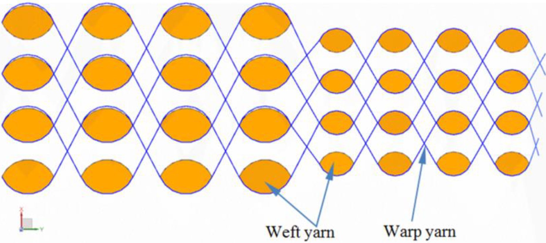
Among the various existing 3-D woven fabrics, 3-D interlock woven fabric 5 –7 and especially, the 3-D layer-to-layer angle-interlock woven fabric (LLAIWF) can provide a relative good compromise between raw material consumption and manufacturing costs. 8 –10 The structure of 3-D LLAIWF is very ingenious, and two layers of weft yarns are joined by weaving of the warp yarns, as shown in Figure 1. Consequently, all the yarns through the thickness are joined by weaving. The resulting material is 3-D with no third yarn set in the transverse direction, but the properties through the thickness are much improved. 11 This structure is very simple, but the possible delaminations of the 2-D laminated composites are overcome. Furthermore, the most attractive advantage of 3-D LLAIWF is the near-net shape-forming capacity to manufacture complex shapes and structural composite parts in different sizes due to excellent deformability, 2,12 –15 especially in-plane shear behaviors. 16

Structure of 3-D layer-to-layer angle-interlock woven fabric.
Variation of fabric thickness
The 3-D woven fabric-reinforced composite blades have been successfully applied to aeroengines, such as the fan blade of Leap-1C aeroengine. The main characteristic of aeroengine fan blade fabric is that the thickness gradually varies in both longitudinal and transverse directions (see Figure 2). There are two ways to change fabric thickness. First, the yarn fineness are changed. The weft yarn fineness can be different in various places of the fabric along the warp direction. Finally, the thickness of the reinforcement can vary along the part (see Figure 3). Second, the number of yarn layers is reduced and then, the thickness of the fabric is reduced (see Figure 4). Both methods have their advantages and disadvantages. For the first method, the production process is simple, but the range of thickness variation is limited. For the second method, the thickness of prefabricated parts can be greatly changed, but the production process is very complex due to warp yarns that need to be rearranged.

The forming stage of blade fabric.
The thickness of the fabric is changed by changing the yarn fineness.

The thickness of the fabric is changed by reducing the number of yarn layers. (a) The outer yarns are reduced and (b) the inner yarns are reduced.
In-plane shear deformability of the fabric
From the 3-D LLAIWF, composite parts are obtained by resin transfer molding (RTM) process. This process is composed of two main stages. First, the 3-D LLAIWF is formed to obtain the geometry of the final part. Subsequently, resin is injected within porous fabric. The final composite part can be complex, such as aeroengine fan blades. This geometry of blade is double curved and the thickness is variant, in-plane shear strains are necessary to reach the shape. The deformability of the fabric defines the fiber orientations and density, which influences directly the permeability of the fabric, and, finally, the mechanical response of a composite component. 17 Yarn fineness and number of yarn layers influence directly the in-plane shear deformability of the fabric. 18,19
At present, excellent in-plane shear deformability of 3-D LLAIWF has been widely recognized by researchers. 12,20 –22 Despite all of these existing research results, choosing the optimized combinations of deformability and process parameters of a 3-D LLAIWF, responding to given specifications of the final composite material solution, is still quite a challenge. One of the reasons that could explain this difficulty may lie in the lack of experimental data of this specific 3-D LLAIWF. Moreover, a clear understanding of the influence of product and process parameters, considered alone or combined together, has not yet been revealed.
Thus, the objective of this article is to provide more knowledge on deformability of 3-D LLAIWF with different yarn fineness or layers. Two kinds of 3-D LLAIWF were designed and produced by changing the yarn fineness and the number of yarn layers. The influence of yarn fineness and the number of yarn layers on the in-plane shear behaviors in the case of the 3-D LLAIWF was studied by bias-extension test, during the bias-extension tests, force, displacement, and image data were collected. Then, shear angles in different zones were determined by the image correlation software (UG NX 11.0). Finally, we discussed the influence of yarn fineness and yarn layers on the in-plane shear deformability of the fabric.
Materials and experiments
Materials
T300 carbon fiber 3-D LLAIWF was used in the current work, and the basic properties are listed in Table 1. This fabric is a plain weave with thickness change by reducing the number of yarn layers (sample L) or reducing yarn fineness (sample D). There are yellow tracing yarns in the weft direction and white tracing yarns in the warp direction in the surface of the fabric (Figure 5). The tracing yarn is used to measure the shear angle of the fabric and to observe the change of the mesostructure of the fabric. The shear angles of the sample S with tracing yarns and without tracing yarns were compared by experiments. The results show that the tracing yarns have no effect on the deformability of the samples. The preparation process of T300 carbon fiber 3-D LLAIWF is shown in Figure 5. Firstly, the fabric is cut along the direction of 45° with the yarn. Secondly, the clamping parts at both ends of the sample were cured with room temperature curing resin. Finally, the aluminum sheet is pasted on both ends of the cured sample.

Carbon-fiber 3-D layer-to-layer angle-interlock woven fabrics for the bias-tensile test: (a) plain weave, (b and c) tailoring and tracing yarns, (d) solidifying, and (e) sticking aluminum sheet.
Material properties of the fabric.
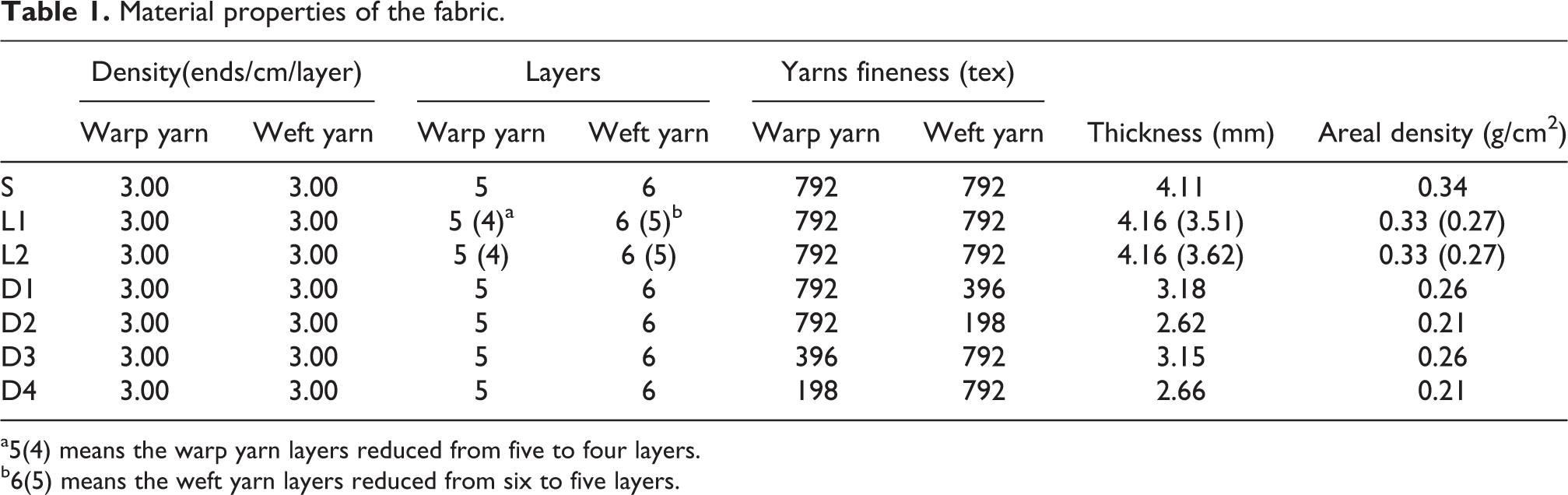
a5(4) means the warp yarn layers reduced from five to four layers.
b6(5) means the weft yarn layers reduced from six to five layers.
Sample L changed the thickness by reducing the number of yarn layers, and the line of reducing yarns is in the center of the sample (see Figure 6). Sample L1 reduced yarn layers by the method shown in Figure 4(a) and sample L2 by the method shown in Figure 4(b). The thickness of sample D remains unchanged, but the fineness of warp yarns is different from weft yarn, so this fabric is called unbalanced. More extensive experimental campaigns should be carried out to determine the strain threshold until which the integrity of the unbalanced fabric is preserved. 23 The thickness of sample S remains unchanged, and all yarns have the same fineness. According to the experimental requirement, the sample was cut to a rectangular shape with dimensions of 210 × 70 mm2, while the effective dimensions are 140 × 70 mm2, 23 as shown in Figure 6. Five samples were tested for every configuration.
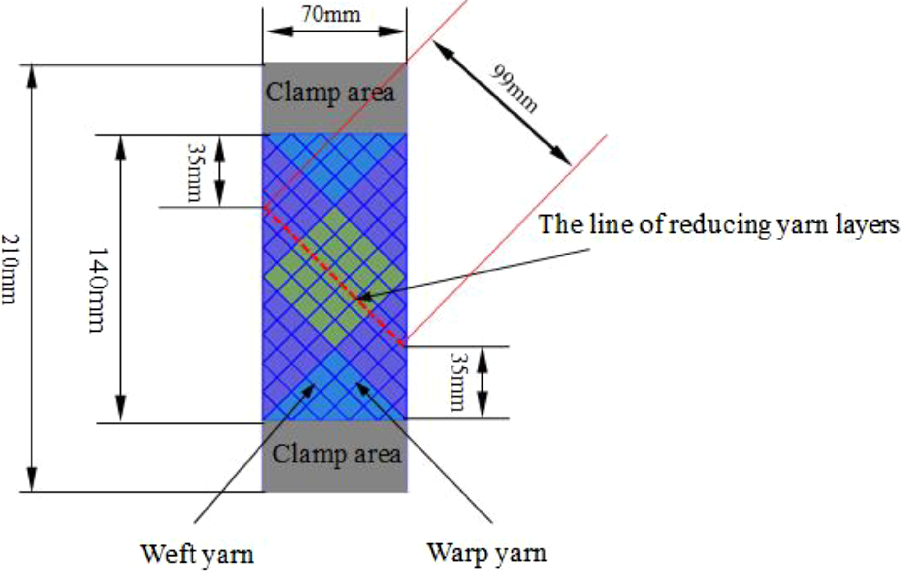
Diagram of sample L.
Equipment
The samples were tested using a Shimadzu 1-kNE universal testing machine (Japan), and the load cell of the testing machine was 1 kN. All bias-extension tests have been carried out at a displacement rate of 10 mm/min. 24 Images were collected by digital image correlation (DIC) (see Figure 7) during the bias-extension tests. Then, shear angles in different zones were determined by the image correlation software (UG NX 11.0) by manual measurements.

Tensile test with digital image collecting setup and shear angle measurement: (a) image collecting and (b) the location of each measured angle.
The bias-extension test is a mechanical test very well-known in the field of woven composite manufacturing and is used for in-plane shear characterization of woven fabrics. 16,25 –30 This test is performed on a rectangular sample, where the fibers in warp and weft directions are initially oriented at ±45° from the load direction (see Figure 8). The ratio λ between the length H and width W of the sample should not be smaller than 2 (λ = H/W) to obtain pure shear in the center of the sample. It is generally assumed that there are three shear states: in zone A, no shear deformation occurs; in zone C, pure shear zone occurs; and in zone B, the shear angle is half of that in zone C. However, zone B1 and zone B2 are asymmetric for sample L, and zones B1 and B3 are asymmetric for sample D, so the carbon fiber 3-D LLAIWF showed a different deformation pattern, which will be discussed in the following section.

Diagram of the (a) initial and (b) deformed sample under a bias-extension test.
Shear angle
When woven fabric is under external force, the rotation of yarns at their crossovers will occur. The variation in the angle of warp and weft yarns after deformation is defined as “shear angle: γ.” 31 As shown in Figure 8, assuming that the angle between warp and weft before deformation is 90°, the resulting deformation due to external load will change the angle to θ, so, γ = 90° − θ. The critical angle is called locking shear angle (γ locking). 32 Bias-extension test provides a simple method of estimating a material’s γ locking, that is, the angle at which intraply sliding and/or out-of-plane bending (wrinkling) become significant deformation mechanisms. 33 γ locking is an important index of fabric deformation performance, but it is difficult to measure accurately. In this article, the shear angle in the zone of C is considered the γ locking when the shear angle is basically unchanged.
Results and discussion
Shear angle during bias-extension test
There are several ways to determine the shear angle in zone C of the material during the test. 34 First, the shear angle can be calculated by equation (1):
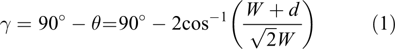
where W is the width of the sample and the length H = 2W. The assumption of this method is that there is no slippage between the yarns. The second one is DIC technology. 16 The test is susceptible to intraply slip as the fabric reaches relatively high shear angles. This slip limits the maximum shear angle that can be explored using the first method. The second method is not suitable for this study due to the sample in this study is asymmetric. This fabric asymmetry is caused by the differences between the warp yarn and the weft yarn fineness. In area B, the finer yarn is easily drawn from the fabric. It makes the fabric surface more uneven. So, it is difficult to measure the in-plane shear deformation properties of fabrics for DIC technology. Because the more flat the sample surface is, the better the measurement is. Further, the surface of the sample used in DIC technology must be painted. It is difficult to observe the change of the mesostructure of the sample.
Therefore, we only use DIC technology to collect sample images but do not use this technology to process the images. Then, it is not necessary to paint the fabric surface. Finally, shear angles in different zones were determined by the image correlation software (UG NX 11.0) by manual measurements.
The measuring is done in the different part of the sample to make sure that the measurement results are comprehensive. Figure 9 shows the evolution of shear angle during bias-extension test for sample S. The result is consistent with the literature. 16,31,35 The shear angle in zone B is half the value of the one zone C (pure shear). 24 In addition, the experimental and computational results in the C zone are consistent at low shear angles, but the consistency becomes less so as the shear angle increases.

Shear angle versus displacement of sample S in bias-extension test.
The sample D is bilaterally asymmetrical. Such as sample D1, the thick yarn in zone B1 is clamped, and the thin yarn in zone B2 is clamped. The shear angle of B1 zone and B2 zone was measured to analyze the asymmetry of sample D, as shown in Figures 10 and 11. There is a small shear deformation in area A, and the shear angle is less than 5°. The point of divergence between calculation and measurement for sample S is earlier than that of sample D (see Figures 9 and 11). The yarns of sample S are thick, then the space between the yarns is small, and the space for the yarn to rotate around the weaving point is small. So, the point of divergence between calculation and measurement for sample S is earlier.
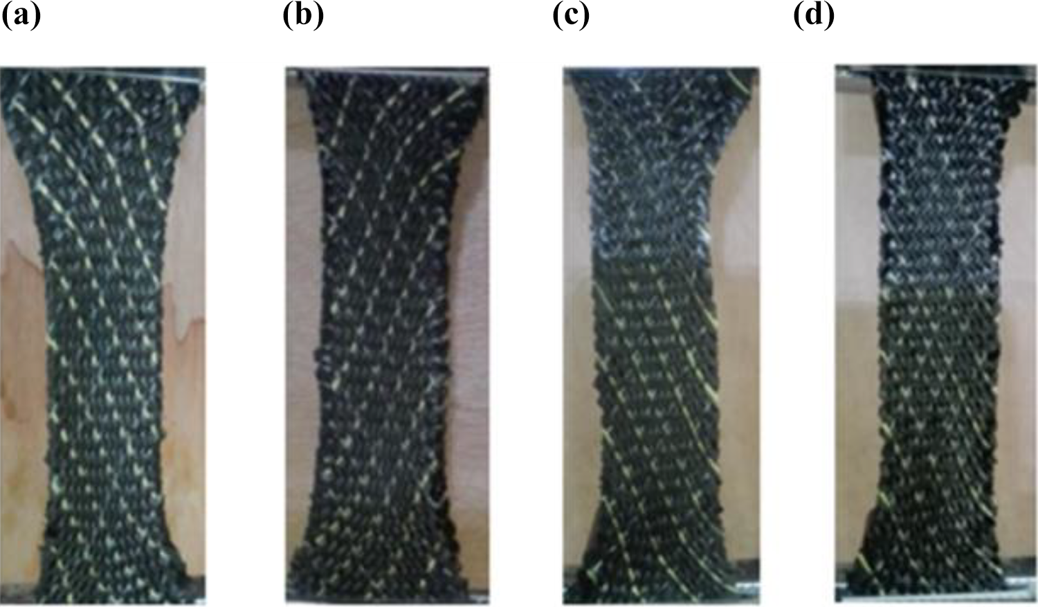
The deformation of sample D during bias-extension: (a) sample D1, (b) sample D2, (c) sample D3, and (d) sample D4.

Shear angle versus displacement during the deformation process of sample D: (a) sample D1, (b) sample D2, (c) sample D3, and (d) sample D4.
The shear angles of B1 zone and B2 zone are different due to the asymmetry of the sample. The bigger the difference between the warp yarn and the weft yarn fineness is, the bigger the difference between shear angle of sample B1 and that of B2 will be. The difference of shear angle between sample D1 and sample D3 is very small. The main feature that determines the properties of the fabric is the friction between the yarns and the in-plane bending stiffness of yarns that both prevent the slipping and generate the shear rigidity of the woven fabric. This shear stiffness greatly influences the overall deformation of the fabric being usually orders of magnitudes lower than the elongation stiffness of the yarns. Unbalanced fabric with different warp and weft fineness leads to peculiar responses, such as shown in Figure 12. The bending stiffness of warp and that of weft is different due to that the fineness of them is not the same. More particularly, the thick yarns are sensible to exhibit higher resistance to bending. Depending on the nature of the externally applied load and/or boundary conditions, the yarns can experience some relative slipping. More precisely, it is possible that the contact point between two yarns can move during the deformation of the macroscopic piece, as shown in Figure 12.

Deformation of the thick and thin yarns as observed.
Considering sample L is up–down asymmetrical (see Figure 13), the shear angle of C zone in the upper and lower part of the sample L was measured, respectively. The shear angle of sample L1 is smaller than that of sample L2. The structural parameters of these two samples are same, but the location of reducing yarn is different. It can be seen that an obvious gap is in sample L2 (see Figure 14) by the observation of its mesostructure. The interlayer interaction of fabric is weakened due to the existence of gaps, and the deformation of fabrics is easier. The shear angle of C1 is larger than that of C2 due to that it is easier to deform after yarn layers were reduced.

(a) Shear angle versus (b and c) displacement of sample L.

Mesostructure of the sample L2 with reduced inner yarns: (a) surface of sample L2 and (b) section view of sample L2.
Mechanical behaviors in bias-extension test
The load of sample D and that of sample L during bias extension is shown in Figure 15. It can be seen that the nonlinearity is the main feature of the relationship between the load and the displacement. In addition, the curves rise smoothly and the relative deviations are smaller for sample D. However, the curves rise quickly, and the relative deviations are larger for sample L. For sample D, the contact area between yarns is smaller due to the yarns are thinner, so friction is relatively small, then the load is smaller than the load of sample L. There are many yarn ends in the valid zone of sample L due to the decrease of yarn layers. So, the relative deviations are larger for sample L. The load of sample D1 is similar to that of sample D3 and the load of sample D2 is similar to that of sample D4 due to that warp and weft have the same status in plain weave fabric. The load of sample L1 is larger than that of sample L2. The outer yarns were reduced for sample L1, and the inner yarns were reduced for sample L2. There is a gap in sample L2 due to reducing yarns. This gap will affect the mechanical properties of fabric, so the load of sample L2 is smaller. The main advantage of the bias-extension test is a useful assessment of the critical shear angle before interyarn slippage, compression, wrinkling, pulling out happens. These are failure mechanisms, which may occur during shear process, especially when yarns are free-ended. When the shear angle reaches γ locking, the load is called locking load (F locking). The γ locking and F locking are shown in Figure 16(a). It can be seen that sample S has largest F locking, and its γ locking is the smallest. Sample D4 has largest γ locking, and its F locking is the smallest. The γ locking and F locking of sample D1 are similar to that of D3. The γ locking and F locking of sample D2 are similar to that of D4. When other parameters of the fabric are unchanged, the smaller the yarn fineness is, the larger the γ locking and the smaller the F locking are.
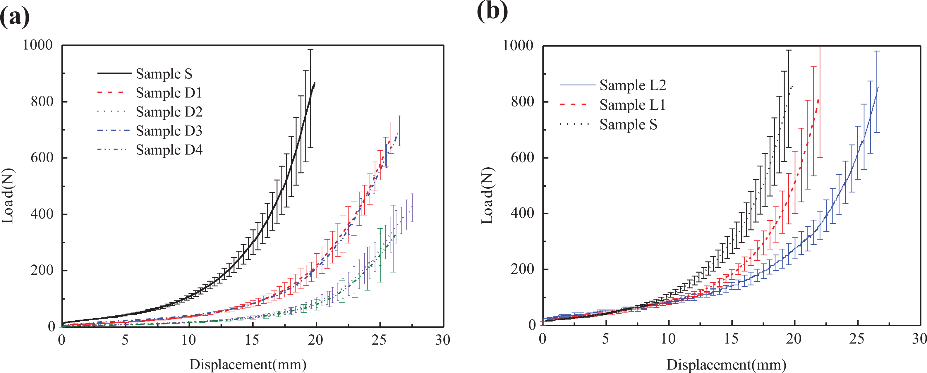
Load versus displacement during the deformation process of (a) sample D and (b) sample L.
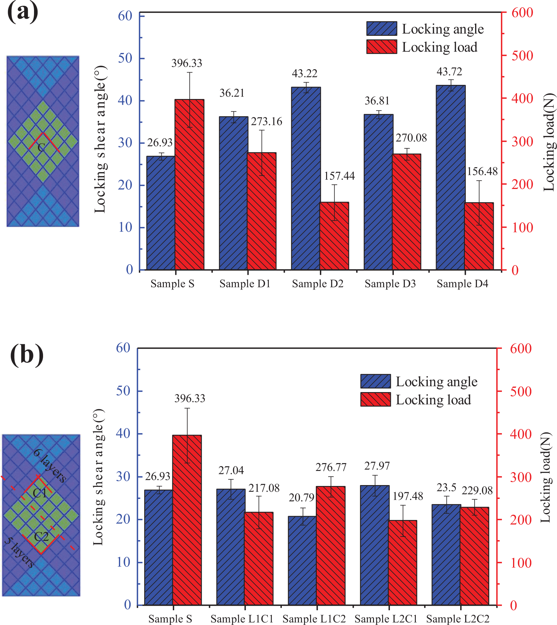
Locking shear angle and locking load in bias-extension test: (a) sample S and sample D and (b) sample S and sample L.
Figure 16(b) is γ locking and F locking of sample L in bias-extension test. It can be seen that the F locking of sample L is smaller than that of sample S due to that the yarn layers of sample L are reduced. The C1 zone with five-layer weft yarns achieves the locking state first, then the C2 zone with six-layer weft yarns achieves. The shear angle in C1 zone is larger than that in C2 zone. The effect of interlayer coupling in C1 zone is smaller than that in C2 zone, and the shear deformation in C1 zone is easier, so the shear angle in C1 zone is larger. The γ locking of sample L1 is smaller than that of sample L2, but F locking of sample L1 is larger than that of sample L2. This gap in sample L2 will affect the mechanical properties of fabric, so the load of sample L2 is smaller.
Conclusions
This work investigated the effect of yarn fineness and the number of yarn layers on the in-plane shear behaviors of carbon-fiber 3-D LLAIWF in bias-extension test with experimental tests.
Changing yarn fineness is an effective way to realize the change in fabric thickness. The yarn fineness combination of samples D1–D4 is 792 tex × 396 tex (warp is 792 tex, weft is 396 tex), 792 tex × 198 tex, 396 tex × 792 tex, 198 tex × 792 tex, respectively. The in-plane shear deformation of the left and right sides of sample D is different due to the asymmetry of this sample. In the B zone, the thin yarns were pulled out from the thick yarns. The tensile load of sample D is smaller than that of sample S (792 tex × 792 tex). For plain weave 2.5-D woven fabric, warp yarn and weft yarn play the same role in the bias-extension process. The in-plane shear properties of sample D1 (792 tex × 396 tex) and D3 (396 tex × 792 tex) are similar. Their locking shear angles are 36.21°and 36.81°, and their locking loads are 273.16 and 270.08 N, respectively. The in-plane shear properties of sample D2 (792 tex × 198 tex) and D4 (198 tex × 792 tex) are similar too.
Reducing the number of yarn layers is another way to realize the change of fabric thickness. When the number of yarn layers is reduced from 6 to 5, the in-plane shear deformation of upper and lower parts is different. The C2 zone with six-layer weft yarns achieves the locking state first then the C1 zone with five-layer weft yarns achieves. The shear angle in C1 zone is larger than that in C2 zone. Reducing the internal yarns of the fabric (sample L1) created a gap, where the yarns were reduced. The load of the sample with reducing external yarns (sample L2) is larger than that of the sample with reducing internal yarns. The γ locking of sample L1 is smaller than that of sample L2, but F locking of sample L1 is larger than that of sample L2.
Footnotes
Declaration of conflicting interests
The author(s) declared no potential conflicts of interest with respect to the research, authorship, and/or publication of this article.
Funding
The author(s) disclosed receipt of the following financial support for the research, authorship, and/or publication of this article: This work was supported by the city of Tianjin colleges and universities innovation team project (TD13-5043).