
Abstract
Glass fiber-reinforced polymer (GFRP) composites are widely applied in automotive and shipbuilding industry. However, impact damage is unavoidable to the composites during production or service, and the evaluation of performance degradation after impact is necessary. The architecture of the fiber preform shows significant influence on the impact damage behavior of GFRP. The present work focused on the influence of preform structure on damage evolution and residual load-bearing capability of the composites. The microstructure and the residual strength after the impact of GFRP with plain-weave preform structure and cross-ply preform structure have been investigated, respectively. The low velocity impact primarily caused matrix cracking and delamination, but unobvious fiber failure to GFRP. More impact-damaged plies were detected in cross-ply composites than plain-weave composites after impact. It indicated that plain-weave preform structure owes better impact damage shielding capability. However, the GFRP with plain-weave preform structure exhibited better impact resistant ability under low impact energy but less residual strength under high impact energy, compared with the GFRP with cross-ply preform structure. The interaction between the warp and weft fibers made the plain-weave composites absorbing more energy in a single ply, which was the reason for the plain-weave composites to exhibit excellent damage shielding performance but poor residual strength under high impact energy.
Introduction
Glass fiber-reinforced polymer (GFRP) composites are important structural materials with relatively low costs and excellent mechanical performances, which are used in new energy, aerospace, automotive industry, shipbuilding industries and so on. 1–3 Among them, laminated GFRPs are of mainly concerns because they exhibit satisfactory mechanical properties with unidirectional composites and lower price compared with 3-D composites. 4–6 Therefore, laminated GFRP attracts intensive interests in the last decades.
However, a major problem associated with the performance of GFRP is that they generally suffer from impact damage during the production or service. 7,8 Previous studies have demonstrated that the residual strength of fiber-reinforced composites is sensitive to impact damage, which will cause fiber breakage, interface debonding, matrix cracking, and delamination. 9,10 As low velocity impact may result in undetectable damage, it can cause even more serious potential security problems compared with high velocity impact. 11–14 Various studies have reported the influence of impact energy, impact angle, and the shape of the punch on the impact damage of composites. 15–18
Low velocity impact shows more boundary-condition sensitive compared with high velocity impact because the impact duration is long enough for the entire structure to response to the impact. The fiber preform architecture decides the boundary condition for the impact response, which is certain to exhibit significant influence on the impact mode of the composites. Although there already exists lots of literatures about the impact behavior of the composites, the researches focus on the difference of fiber architecture and impact damage mode is still lacking. There are few works focus on the differences of impact damage between plain-weave and cross-ply composites by far while both kinds of composites are used in large scale. Here in this work, the impact damage of these two kinds of composites has been tested and the influence of different preform structure on damage evolution and residual load-bearing capability of the composites has been discussed.
Experiments
Materials
The materials used here were custom-built glass fiber-reinforced epoxy resin composites with cross-ply and plain-weave preform structure, respectively. The glass fibers prepreg used were received from Lingyun Industrial Corporation (Quingpu District, Shanghai, China). The fiber preforms were received in the form of glass cloth prepreg in both plain-weave and unidirectional form. The tows in both plain-weave and unidirectional prepreg were shaped by the epoxy resin. The density of the prepreg was 70 g/m2 with a thickness of approximately 80 µm. The epoxy resin impregnated was a bisphenol A liquid epoxy E54 and the curing agent was 4,4′-diaminodiphenylsulfone (obtained from Alfa Aesar, Shanghai Chemical Industry Park, Shanghai, China) with a weight ratio of 100:30.
Before the final molding of the composites, each type of prepreg cloth was cut into rectangle shape pieces with dimensions of 600 × 600 × 5 mm3 and stacked individually. For the plain-weave cloth, the stacking direction of the prepreg cloth was kept the same. The unidirectional cloth was stacked in the 0°/90°/0°/90°/…manner to form the cross-ply preform. The preforms were vacuum preloaded for 1 h and then elevated to 80°C with a temperature rate of 2°C/min and kept at 80°C for 10 h to cure the epoxy resin matrix. After that, the prepared composites were cooled to 60°C and unloaded from mold.
The preform structures of the two types of composites are shown in Figure 1. After the curing process, the obtained composites were hand polished using abrasive papers with granularity of 800 and 1500. As for simplification, the GFRP with cross-ply preform structure was labeled as CP60-GFRP, and that with plain-weave preform structure was labeled as PW60-GFRP. The final densities of CP60-GFRP and PW60-GFRP were 2.3 ± 0.1 and 2.2 ± 0.1 g/cm3 with a volume fraction of glass fiber of 60 ± 2%.

(a) Illustration of the preform structure (up: plain-weave structure and down: cross-ply structure); (b) a schematic illustration of the impact setup; and (c) a brief description of specimen cutting from the impact-damaged sample and the setup of the flexural test.
Impact test
The impact tests were carried out using a SANS ZCJ1302 drop weight impact testing machine with a maximum impact energy of 300 J at ambient temperature. The specimens used in the impact tests were with a size of 100 × 100 × 5 mm3 and fixed on the testing machine using a home-made fixture. The radius of the impact punch was 25 mm with adjustable drop weight (5 kg in the present test) and the shape of the impact punch is shown in Figure 1(b). The impact energy levels were 5, 10, 20, 40, and 80 J by adjusting the drop height of the punch. After the impact tests, the specimens were cut through the central point of the impact area using a diamond saw and polished using abrasive papers with granularity of 800 and 1500 for the characterization of impact damage using a stereomicroscope (Leica EZ4). For the accuracy of the results, at least three specimens were tested for each energy level and preform type.
Residual strength and modulus tests
The residual modulus of the specimens was characterized in two different scales: in nanoscale and in macroscale. The test of modulus in nanoscale was carried out using a nano-indentation instrument (Hysitron TI980, Minneapolis, USA). The applied load was 10 mN to avoid the plastic deformation of the polymer matrix. The indenter used is a Berkovich type indenter and the loading rate was set to 100 nN/min. The loading direction of the nano-indentation process was vertical to the polished surface illustrated in Figure 1(c).
The residual strength and modulus in macroscale were obtained using a three-point bending method with the specimen size of 60 × 100 × 5 mm3. The span of specimens was 40 mm, and the loading rate was 1 mm/min. The placed mode and the loading direction of the composites during the flexural tests are also shown in Figure 1(c).
Results and discussion
There are two major difficulties existing in predicting the impact behavior of GFRP composites: (1) the complexity of GFRP microstructures which is mainly caused by the spatial distribution of fibers and the unfamiliar failure behavior of fiber–matrix interfaces and (2) the detection and quantification of impact damage. Due to the reasons mentioned above, the methods based on numerical simulation hardly provide satisfactory conformance in predicting the residual strength of GFRP after impact damage. Thus, in the following contents, two problems were addressed in characterizing the impact damage of GFRP: (1) how to characterize the impact damage quantitatively and (2) how residual strength evolves after impact damage. In the first part of this section, we discussed the damage evolution after impact. Specially, the effect of differences in preform structures on the damage type and degree was studied in detail. Subsequently, a comparison between residual strength of CP60-GFRP and PW60-GFRP was provided and analyzed systemically.
Influence of impact energy on the damage
There are various aspects that influence the damage evolution during the impact tests. One major concern is how the impact energy affects the damage type and degree inside the composites. Figure 2 shows the cross-section morphology of CP60-GFRP and PW60-GFRP composites. As low-energy impact causes unobvious deformation in the macroscale, no detectable fiber breakage was observed. The major damage types were matrix cracking and delamination. Also, it can be observed that the ability of damage shielding was quite different between the two kinds of composites. For the PW60-GFRP composites, there was a clear distinction between the damaged and undamaged layers, which indicated excellent damage shielding ability of the composites. Meanwhile, the undamaged area in CP60-GFRP composites was mixed with a little damaged structure, which indicated that the damage can penetrate to the undamaged area. This difference in damage shielding was closely related to the preform structure: the plain-weave structure can resist the impact in both x- and y-direction in each ply while only the impact along the fiber orientation can be resisted for the cross-ply preform. As a result, some of the impact waves which possess components vertical to the laminate plane can propagate into the next ply and cause impact damage.

Typical cross-section morphology of (a) PW60-GFRP and (b) CP60-GFRP composite after the impact. GFRP: glass fiber-reinforced polymer.
Figure 3 shows the number of plies which have suffered from impact damage under different impact energy. It can be observed that with the increase of impact energy, the number of damaged plies increased continuously for both PW60-GFRP and CP60-GFRP. And due to better shielding ability of impact damage, the number of damaged plies in PW60-GFRP was less than that in CP60-GFRP under the same impact energy level. From the above analysis, it can be informed that the energy absorbed in a single ply for PW60-GFRP was more than that in CP60-GFRP, which indicated that the coupling of the warp and weft fibers can consume more energy during the impact. However, a clear elaboration of the inherent mechanism requires further study at microscale, which would be carried out in further studies.

The number of damaged plies varied with impact energy for both PW60-GFRP and CP60-GFRP. GFRP: glass fiber-reinforced polymer.
Residual modulus in both microscale and macroscale after impact damage
Based on the above analysis, it is found that low energy impact causes damage inside the ply and delamination. Both types of damage can cause the degradation of modulus of the epoxy resin. The degree of damage inside the matrix can be characterized by monitoring the modulus of the matrix, which can be realized by the nano-indentation method. Figure 4(a) shows the typical depth-load curve of the nano-indentation process in the matrix. It can be observed that the initial displacement of the indenter and the final position of the indenter after the unloading process do not superposition with each other, indicating some degree of plastic deformation of the resin during the indentation process. The in-situ modulus of the epoxy resin can be calculated using the following equation 19
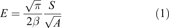
where S is the slop of the curve at the initial of the unloading process, A is the projected area of the indenter on the sample at maximum loads, and β is a constant associated with the shape of the indenter. Figure 4(a) clearly demonstrates that a detectable degradation of the matrix modulus occurred with the increase of A and decrease of S after the impact test.
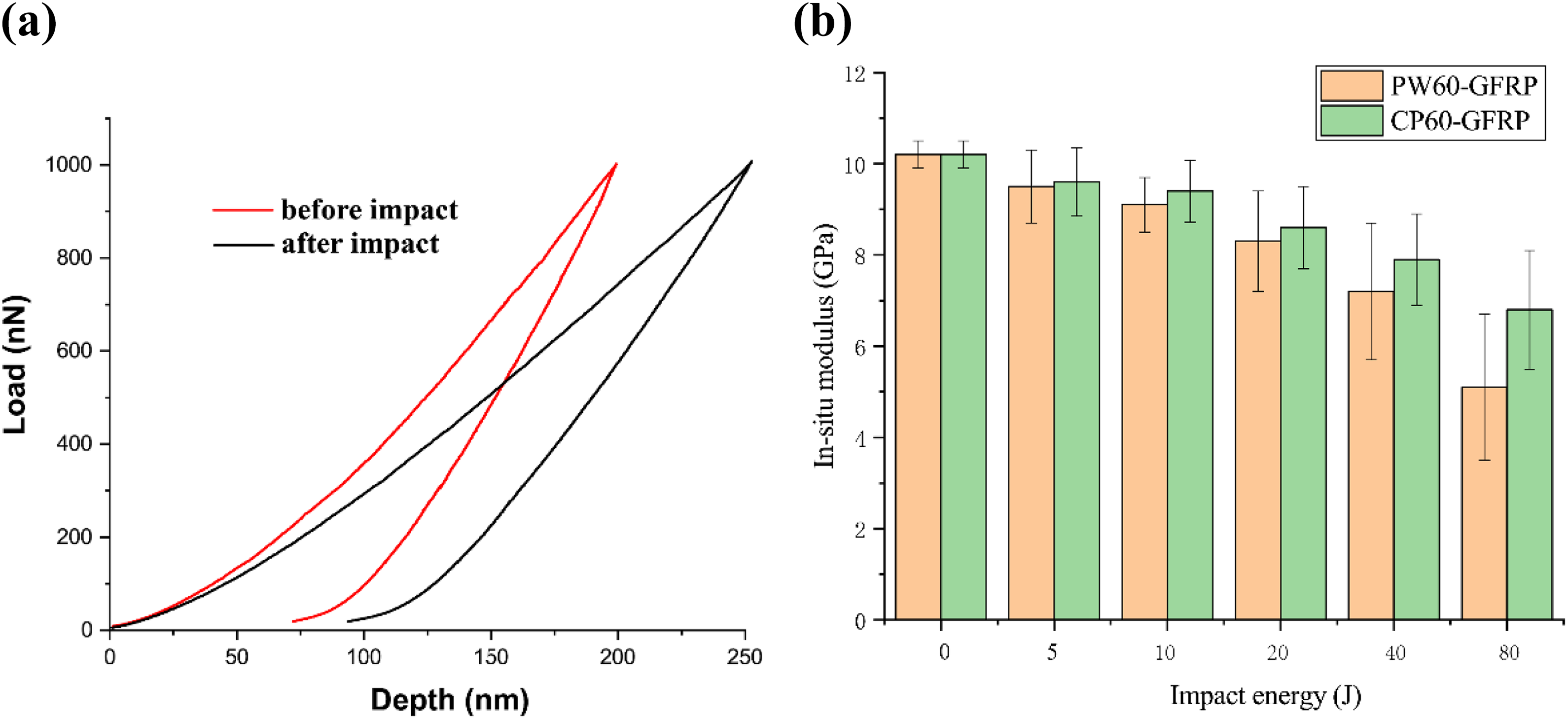
(a) Typical depth–load curve in the nano-indentation test for the matrix in PW60-GFRP composites before and after the impact with an energy of 20 J and (b) the residual modulus varied with impact energy. GFRP: glass fiber-reinforced polymer.
The initial modulus of the epoxy resin was 10.2 ± 0.3 GPa without impact damage by calculation based on equation (1). For PW60-GFRP composites, the residual modulus of PW60-GFRP composites was lower than that of CP60-GFRP composites after each impact energy test. This was consistent with the conclusion that each damaged ply in PW60-GFRP absorbed more energy than that in CP60-GFRP. Also, it can be observed from Figure 4(b) that as the energy of impact increased, the in situ residual modulus decreased nonlinearly. Besides, it can be found that the variation of residual modulus decreased as the energy increased continuously.
The residual modulus in macroscale can be estimated by the three-point bending method. Figure 5 shows the residual modulus in macroscale. Two critical phenomena can be observed here: (1) at relatively low impact energy (<20 J), the residual macroscale modulus decreased slightly and higher energy causes more serious modulus degradation; and (2) with the increase of impact energy, the decline of residual modulus of CP60-GFRP was less than that of PW60-GFRP. It is implied that CP60-GFRP can exhibit better resistance capacity under high impact energy. At the meantime, it should be mentioned that modulus degradation was a synergy effect of delamination, matrix cracking, and fiber–matrix degradation. A severe modulus degradation was detected in macroscale than that in nanoscale, indicating the delamination and fiber–matrix interface debonding took place at the same time. Also, it can be inferred that both delamination and fiber–matrix interface debonding occurred at relatively high impact energy.

Residual modulus in macroscale varied with impact energy for both PW60-GFRP and CP60-GFRP composites. GFRP: glass fiber-reinforced polymer.
Residual strength of PW60-GFRP and CP60-GFRP
Residual strength determines the capability of re-bearing after impact, which is an extremely important aspect for security. So far, most of the studies focused on the residual compressive strength of the impact-damaged composites. 20,21 However, the most common stress situations can generally be simplified into simply supported beam, where flexural stress is the dominated situation. Therefore, in the following content, the residual flexural strength of the impact-damaged composites was investigated. The loading direction of the specimen is shown in Figure 1(c).
As is well-known, polymer matrix composites generally exhibit a period of nonlinear deformation before the final failure (Figure 6(a)). This nonlinearity of deformation originates from mainly three aspects: plasticity deformation of the polymer matrix, fiber–matrix debonding, and fiber pulling-out. The intact specimen and impact-damaged specimen all exhibit a rather low period of nonlinear deformation. However, the maximum stress of the intact specimen occurred at a relatively low strain and followed by a slight decrease of stress before failure, which might be the result of fiber failure. But the maximum stress of the impact-damaged specimen was achieved at a relatively larger strain due to the decrease in interface bonding.

(a) Typical stress–strain curves for PW60-GFRP before and after impact under an impact energy of 20 J. (b) Residual strength of both PW60-GFRP and CP60-GFRP varied with impact energy. GFRP: glass fiber-reinforced polymer.
The residual strengths of both composites follow the same tendency as the macroscale modulus as shown in Figure 6(b). In short, it can be summarized that plain-weave composites exhibits better impact resistant ability under low impact energy but worse impact resistance performance under high impact energy compared with cross-ply composites.
This can be verified by examining the failure morphology of the composites as shown in Figure 7. PW60-GFRP showed more shear damage inside the ply due to the interaction between the warp and weft fibers. As is known to us, fiber failure occurs when the local high stress excesses the in situ strength of the fiber or due to high bending stress. In the present situation, the local stress at the shear damaged area was far lower than the fiber strength. Hence, matrix cracking was the predominant damage form that exists in this section. As a result, the strength of plain-weave composites depends on the shear-resistance of the polymer matrix. For CP60-GFRP composites, as fibers orients in the same direction at a single ply, the impact resulted in only severe damage vertical to the fiber direction and the load-bearing ability still preserved after the impact. However, it causes severe delamination than that in plain-weave composites. Thus, the cross-ply composites exhibited better impact resistant ability than plain-weave composites under high impact energy but worse under low impact energy.

The failure morphology of both (a) PW60-GFRP and (b) CP60-GFRP varied with impact energy. GFRP: glass fiber-reinforced polymer.
Conclusions
The low velocity impact primarily caused matrix cracking and delamination, but unobvious fiber failure for GFRP composites.
More impact-damage plies were detected in cross-ply composites than plain-weave composites, indicating that plain-weave preform structure owes better impact damage shielding capability.
PW60-GFRP exhibited better impact resistant ability under low impact energy (5 and 10 J). But CP60-GFRP exhibited better impact resistant ability under high impact energy (20, 40, and 80 J).
The interaction between the warp and weft fibers made the plain-weave composites absorbing more energy in a single ply, which was the reason for PW60-GFRP exhibited excellent damage shielding performance but poor residual strength under high impact energy.
Footnotes
Declaration of conflicting interests
The author(s) declared no potential conflicts of interest with respect to the research, authorship, and/or publication of this article.
Funding
The author(s) received no financial support for the research, authorship, and/or publication of this article.