
Abstract
Additive manufacturing (AM) techniques are increasingly applied with precision and are recognized as valuable tools across various stages of product development and production. The demand for innovative and customized products tailored to individual users is growing rapidly, and AM enables the fast creation of such items, facilitating timely market launches. Among the existing AM technologies, powder bed fusion (PBF) has gained considerable attention due to its ability to produce high-quality parts automatically. This is attributed to its compatibility with a wide range of materials and the superior quality of the final components. Despite its advantages, PBF faces challenges that must be addressed to establish it as a reliable manufacturing method. Various issues, such as poor dimensional accuracy, variations in mechanical properties, defects, residual stresses, surface irregularities, etc., limit its application in high-value, mission-critical products. The primary factors affecting the quality of parts produced by PBF are the processing parameters. Because process parameters are directly related to microstructure development and process-induced defects, optimizing parameter settings and preventing defects such as melt pool geometry is key to ensuring the production of high-quality AM components. Hence, in this work, the role of process parameters and other factors affecting the part quality is discussed in detail. Moreover, the manuscript discusses the role of advanced tools, such as machine learning, in situ monitoring, simulations, etc., to enhance the part quality during PBF-based AM.
Keywords
Introduction
Additive manufacturing (AM) is increasingly recognized as a transformative technology for rapidly producing innovative and customized products tailored to individual users.1, 2 The ability to fabricate complex geometries with minimal tooling and lead time has driven significant interest and investment in AM across multiple industries.3, 4 While the technology has matured considerably over the years, it continues to face several technical challenges that limit its broader adoption in high-performance applications. 5 Among many, poor mechanical properties, defects and surface quality are some of the primary concerns. 6 These issues often stem from inadequate dimensional tolerance, surface roughness, inherent defects such as porosity or inclusions, and residual stresses induced during the manufacturing process. Collectively, these factors contribute to the variability and often reduce the reliability of AM parts compared to conventionally manufactured components. Since the inception of AM, numerous researchers have focused on enhancing part quality, addressing the root causes of defects, and developing robust processing strategies. For example, Saha et al. 7 reviewed the use of various AM processes in fabricating microfluidic devices. The study highlights that although AM offers improved accessibility and design flexibility, it largely struggles with material biocompatibility, optical transparency, prolonged chemical stability and variability. They also specifically underlined that the main challenge with powder bed fusion (PBF) technique is its limited resolution relative to microchannel dimensions, leading to partially fused or blocked channels, high surface roughness and difficulty in complete powder removal from enclosed microstructures. Thus, consistently achieving high-quality components remains a complex challenge due to the sensitivity of the AM process to numerous variables, including material characteristics, machine parameters, and environmental conditions. Variability can occur at different stages, from powder handling to laser scanning, resulting in inconsistent microstructures and mechanical performances.
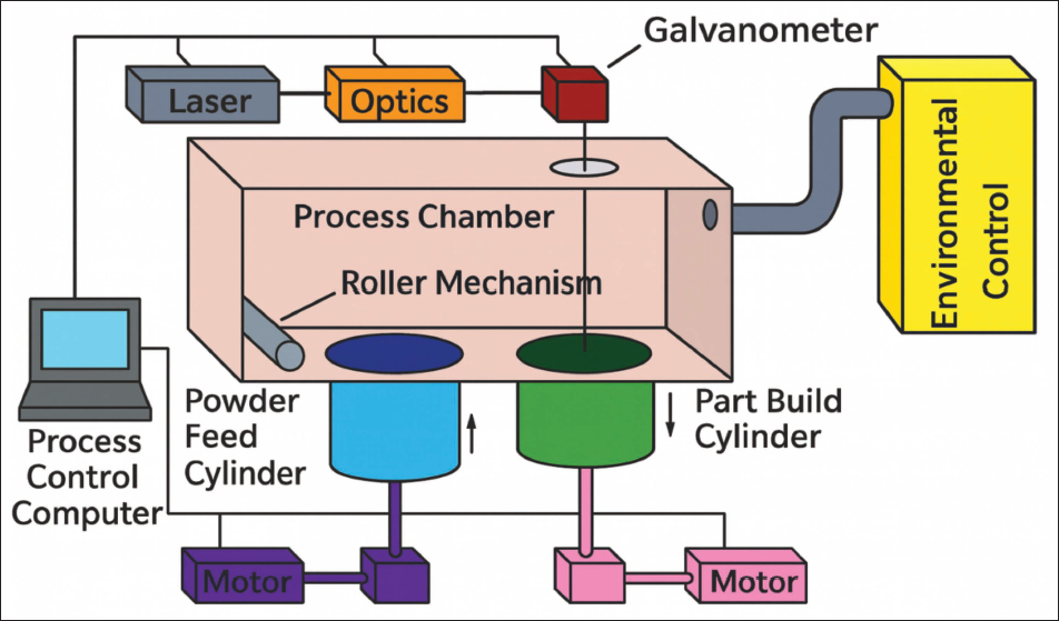
Among the various AM technologies available, PBF is frequently favored for producing parts with superior mechanical properties and surface finish. This preference is largely due to PBF’s compatibility with a broad spectrum of materials, including metals, polymers, and composites, and its capability to produce near-net-shape parts with fine feature resolution. Selective laser sintering (SLS) is one of the most widely used PBF techniques. SLS operates by employing a high-powered laser to selectively fuse powder particles.8, 9 The laser energy overcomes particle surface tension, enabling the powder to coalesce and form solid layers. The SLS process involves two feed cartridges that supply powder material, which is uniformly spread over the build platform by a rotating roller. The build platform itself is mounted on a movable piston that precisely lowers after each layer is formed, enabling the continuous addition of layers as the part is built vertically, as illustrated in Figure 1. 10 The process begins with the creation of a digital model, typically a CAD file, or converting medical imaging data, such as CT or MRI scans, into CAD or STL formats. This model is then sliced into thin cross-sectional layers that guide the laser during fabrication. 11 A computer system controls the laser’s path and energy, ensuring precise layer-by-layer fusion according to the design specifications. To prevent oxidation and mitigate the risk of powder combustion or explosion, the build chamber is filled with nitrogen gas, maintaining an inert atmosphere, as managed by the computer system. The powder is preheated to a temperature just below its melting point to reduce thermal gradients, thereby minimizing distortion and residual stresses while promoting improved bonding between successive layers. The temperature of the powder feed cartridges is carefully regulated to ensure consistent powder flow and deposition, facilitated by the rotating roller that spreads a fine, even layer of powder across the build area. The laser beam is directed through a pair of mirrors that scan the powder bed’s surface selectively, fusing powder particles to form the first layer of the part (Figure 1). After each layer is fused, the build platform lowers incrementally, and the powder feed cartridges supply fresh powder for the next layer. This cyclical process continues until the entire component is fabricated. 12
Selective laser sintering. 8
As a critical AM technology, SLS requires rigorous control over process parameters, material properties, and part positioning within the build chamber to maintain high-quality and performance. Despite these capabilities, various issues, such as inferior mechanical properties, defects and surface roughness, remain a major challenge in advancing the SLS process. Gorana and Modi 12 established that SLS parameters such as powder refresh rate, build chamber temperature and layer thickness influence porosity and strength of polyamide porous bone scaffolds significantly. They also exhibited that effective process parameter optimization leads to a good combination of strength and porosity. Often, mechanical properties, defects, and surface quality are interconnected through the thermal history of the process. 13 This is due to the fact that temperature and time exposure control the degree of powder melting, neck growth, and crystallization during SLS. If the thermal input is insufficient or cooling is too rapid, incomplete coalescence occurs, leading to high residual porosity; these pores act as stress concentrators that reduce tensile strength and fatigue resistance while also producing a rough, partially fused surface. Conversely, higher energy input or prolonged exposure above the melting temperature enhances viscous flow and interparticle diffusion, reducing internal porosity and improving interlayer bonding, which increases strength and stiffness; however, excessive heat can cause over-melting, powder caking around part boundaries, and surface waviness, degrading dimensional accuracy and surface finish. Additionally, the cooling rate governs crystallinity in semi-crystalline polymers like PA12, affecting stiffness and ductility while also influencing shrinkage and surface texture.14, 15 Thus, the thermal history simultaneously dictates microstructural evolution, pore morphology, and surface formation, making mechanical performance, porosity, and surface roughness inseparable outcomes of the same heat transfer and solidification dynamics.
Additional challenges involve limited production speeds, lack of reliability and repeatability, integration of functional materials with SLS processes, managing the high cost of machines, improving energy efficiency and cost-effectiveness at larger production volumes, and understanding the environmental impacts of SLS processes. Furthermore, supply chain complexities, the need to educate designers and engineers about AM benefits, the integration of AM with hybrid manufacturing systems, limitations in automation, and the development of industry standards and certification processes all require ongoing attention. Quality control across distributed manufacturing networks, maximizing machine utilization and addressing the availability and cost of digital designs are critical factors for widespread adoption. The fragmentation and uneven distribution of AM services further complicate the landscape, emphasizing the need for coordinated efforts to streamline and optimize the technology.16–18
SLS fabrication parameters and settings
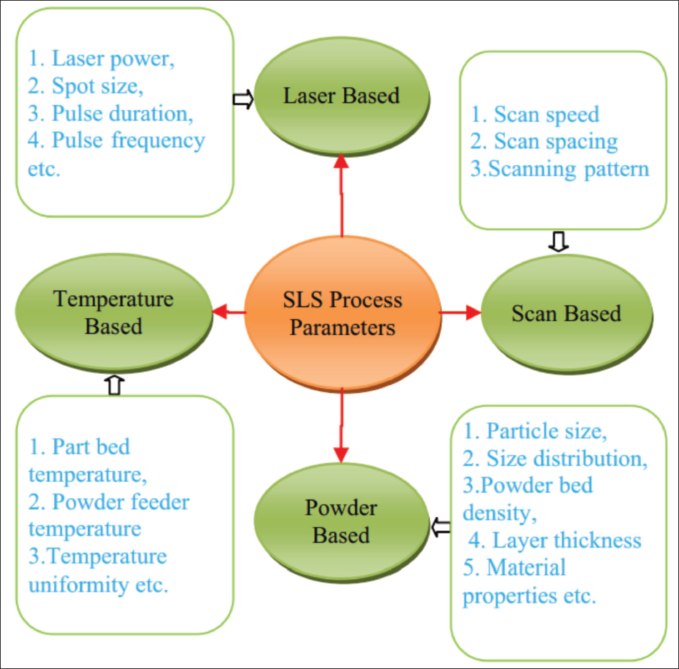
The key fabrication parameters typically include fill-laser power, laser beam speed, laser beam offset, scan spacing, scanning strategy, energy density, slice thickness, and heater control (Figure 2). Tiwari et al. 8 stated that the SLS process involves multiple fabrication parameters that impact the quality of sintered parts. These parameters are adjusted based on the properties of the powder and the specific application requirements. Additionally, the quality of fabricated parts in the SLS process is influenced by various fabrication parameters and factors. Achieving better results depends on the appropriate selection of these parameters, which can be classified into three main categories: (a) process-related factors, (b) material property-related factors, and (c) consolidation mechanisms.
SLS process parameter. 8
Process-related factors
Regarding process-related issues, Gibson et al.
11
reported that the mechanical properties and appearance of SLS parts are influenced by powder material properties, fabrication parameters, part orientation, and post-processing techniques. To achieve optimal surface finish, build rate, and mechanical properties, key fabrication parameters such as powder bed temperature, laser power, laser scan speed, laser beam spot size, layer thickness, hatch distance, and scanning pattern must be carefully optimized for each factor. It has been determined that the mechanical properties and appearance of a fabricated part are primarily influenced by the selection of material, optimized fabrication parameters, part orientation, and post-processing conditions. Tiwari et al.
8
found that the glass transition temperature (Tg) and melting point temperature (Tm) of a polymer influence the part-bed temperature (Tb) and fill-laser power (P). Furthermore, maintaining a uniform and consistent powder bed temperature is essential for achieving repeatable quality results. According to Goodridge et al.,
19
different combinations of part-bed temperature and fill-laser power significantly affect the quality of fabricated parts. A high part-bed temperature combined with high fill-laser power results in dense parts but may cause part growth. Conversely, low part-bed temperature and low fill-laser power enhance dimensional accuracy but lead to lower-density parts with a tendency for layer delamination. Additionally, low part-bed temperatures paired with high fill-laser power can cause non-uniform shrinkage and residual stress buildup, leading to part curling. Furthermore, increasing the laser dwell time at a specific location results in a larger melt pool diameter and greater sintering depth. Proper fusion of powder particles can be achieved by using a low scan speed and reducing laser power. Additionally, other material processing parameters, such as scan spacing (SCSP) and scan size, are determined by powder properties like particle size and density, as well as the specific requirements of the application. An increase in energy density can be achieved by reducing scan speed (SS) and SCSP while increasing fill-laser power. Studies have also shown that higher energy density enhances tensile strength and part density.13, 14 However, an excessively high energy density, due to large fill-laser power and/or low scan speed and hatch scanning, may cause overheating, leading to thermal degradation and over-sintering during SLS. This affects the part quality adversely by promoting excessive particle melting, distortion, warpage, curling, high residual stress, keyholing, etc.
15
In a nutshell, energy density is material-dependent and should remain below a threshold in the interest of process stability. A shorter scan vector as a processing parameter ensures a more uniform temperature distribution during sintering. It also reduces the time required to scan the next section, minimizing heat loss and enhancing the bonding quality of the part. Simchi
20
also emphasized the importance of using the same combination of process parameters to achieve better binding and produce high-quality fabricated parts. Additionally, he stated that the densification mechanism in metal sintering follows the first-order kinetic law, meaning the sintering rate depends on the input of laser energy. The sintering density of metal powder materials is expected to follow an exponential relationship with the amount of laser power applied. In direct SLS of metals, the presence of oxygen negatively impacts the sintering and densification process of the fabricated parts, as it promotes the formation of surface oxides. Blattmeier et al.
21
and Caulfield et al.
22
discovered that the formation of an oxide layer on the surface of powder particles enhances the absorption rate of CO₂ laser radiation. This effect alters the temperature-time profile of the sintering process and increases the melt volume. Additionally, their research indicated that the mechanical properties of the fabricated part are superior in the middle of the build height compared to the extreme positions. Caulfield et al.
22
found that part dimensions tend to increase as energy density levels rise, regardless of build orientation. Additionally, Despeisse et al.
23
highlighted that Hot Isostatic Pressing (HIP) and various post-processing techniques, such as infiltration, coating, and surface finishing, further enhance the density, mechanical properties, and overall appearance quality of SLS-fabricated parts. A higher beam scanning speed (BS) results in a flatter sectional sintering geometry, while increased laser duration leads to greater sintering depth and vice versa. Additionally, higher laser power combined with lower scanning speeds produces larger sintering depth and width. Moreover, an increase in powder packing density contributes to improved quality of the fabricated parts. Kruth et al.
24
studied the characteristics of SLS parts and found that a zigzag scanning pattern enhances part density. Additionally, surface quality can be improved by re-melting the parts 12 times. Moreover, achieving optimal part characteristics and quality depends on selecting the right process parameters and processing the parts under controlled microstructural conditions. Kumar
25
demonstrated that utilizing computational modeling to analyze and optimize various process parameters enhances the efficiency of the SLS machine and improves the quality of the final part. The relationship between fabrication parameters and material properties in the SLS process is outlined below in Equations (1–3). Fill-laser power (P) can be calculated using Equation (1).
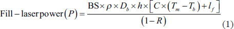
where, ρ is powder density, C specific heat, lf latent melting heat, Db diameter of laser beam on the part-bed and R is reflectivity. It should be noted here that the term “R” depends on the wavelength of the laser, temperature and physical state of the material. The wavelength of the laser depends on its type, for instance fiber laser, a green laser or CO2 laser. The reduction in temperature causes an increase in reflectivity. Further, the material in the solid state has higher reflectivity as compared to the one in molten (liquid) state. In addition to the above, reflectivity also depends on the surface condition. For example, oxidation and surface roughness usually cause a reduction in the reflectivity. Next, the energy density is related to process parameters as per Equation (2).
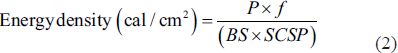
where, f is a conversion factor. Laser beam offset plays a crucial role in determining the accuracy of SLS parts. It encompasses factors such as the laser-spot diameter, the heat-affected area on the powder surface, and the deflection angle during laser scanning. The laser-spot diameter varies at different locations on the powder surface, depending on the deflection angle of the laser beam from the scanning mirror, as shown in Figure 3. When the deflection angle (α) is zero, the laser spot achieves its minimum diameter (D), ensuring optimal focus on the scanning surface. However, as α increases beyond zero, the laser-spot diameter on the scan surface expands, following the relationship D’ = D/cos α. A difference between D’ and D is expressed in terms of additional distance in Equation (3).
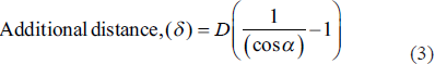
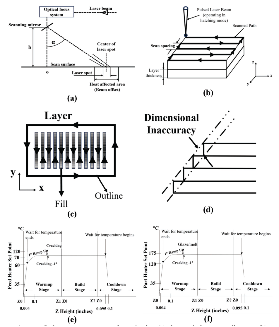
D, however, increases in direct proportion to α, but the increase in diameter is not expected to be significant (approximately 5.4% at the maximum value of α 19˚ and D = 0.42 mm). The effect of this increase is therefore usually ignored.
For high-quality part fabrication using polymer materials, typical processing parameters are selected as follows: The part-bed temperature (Tb) is maintained near the glass transition temperature (Tg) for amorphous materials, while for fully crystalline materials, Tb is set approximately 3°C–4°C below the melting point temperature (Tm). The fill-laser power (P) ranges between 50 W and 18 KW. The SCSP is kept at or below the laser beam diameter on the part-bed, typically ≤ 0.8 mm. The slice thickness (h) varies from 0.07 to 0.5 mm, with the maximum slice thickness constrained by the powder’s penetration depth (Dp). Additionally, the scan size is generally set between 55 and 85 mm.
Material property-related factors
According to Simchi, 20 utilizing a mixture of powders with varying particle sizes enhances the density of parts produced through SLS. Finer particles, due to their smaller size and larger surface area, absorb more laser energy, leading to an increase in working temperature and accelerated sintering kinetics. To promote selective melting, binder material particles are kept smaller than those of the structural material. However, in cases where the binder material, such as Cu or Co, has high reflectivity or low absorption, its preferential melting may be counteracted, particularly when the structural material is a high-temperature metal or ceramic. Kruth et al. 26 observed that combining small and large binder particles improves packing density by reducing pore size. This enhanced packing promotes the rapid spreading of molten binder through capillary action and facilitates quicker particle rearrangement. Additionally, the initial powder packing density influences the final density of SLS-processed parts. A higher sintering density and a rigid network of high-melting-point solid particles can restrict the flow of low-melting-point particles, limiting their ability to rearrange during the process. In the case of lower-density sintered parts, the liquid phase can freely flow, facilitating the rearrangement of solid particles and leading to improved densification. Shi et al. 27 found that material viscosity, which depends on molecular weight, significantly influences the density of SLS-fabricated parts. Higher viscosity materials tend to produce parts with greater density. Additionally, the quality of SLS parts is affected during the melting process, as an increase in crystallinity impacts both shrinkage and dimensional accuracy. A larger gap between the melting peak and the crystalline peak results in higher dimensional accuracy. Additionally, particle size plays a crucial role in determining the minimum layer thickness and directly influences the precision of the fabricated part. Higa 28 observed that smaller particles are preferred for their advantages; however, they are more prone to oxidation due to their increased surface area compared to larger particles. Absorptance refers to the ratio of absorbed radiation to the total incident radiation and is a crucial factor in the SLS process, particularly when sintering a two-component powder mixture. In loose powder, a portion of the incident radiation is absorbed by the outer surface of the particles, while the remaining radiation penetrates through the gaps between particles, reaching deeper layers and interacting with the underlying material. 29 According to Tiwari et al. 8 and Simchi, 20 laser absorption is generally higher in solid materials due to multiple reflections of the laser beam within the layer, which enhances energy retention. In contrast, within powder beds, multiple reflections between particles lead to increased optical penetration depth compared to bulk materials. The SLS process utilizes two primary laser sources: CO₂ and Nd:YAG lasers. The absorption characteristics of different materials depend on the laser wavelength, significantly impacting particle consolidation during sintering.
The CO₂ laser, with a wavelength of 10 µm, is highly suitable for sintering polymer powders, as these materials exhibit strong absorption at longer wavelengths. It is also an effective choice for processing oxide ceramics. In contrast, the Nd:YAG laser, which operates at a 1.06 µm wavelength, is more appropriate for carbide ceramics and metals since metals absorb energy more efficiently at shorter wavelengths. 29 According to Higa, 28 a material’s reflectivity is primarily influenced by its electrical conductivity. Metals, which have high reflectivity, require a higher energy density for effective processing. However, materials with high thermal diffusivity allow for deeper fusion diffusion without causing thermal shock or part cracking.
Consolidation mechanisms related factors
Consolidation mechanisms are fundamentally different between polymers and ceramics or metals during a typical laser sintering process. In the case of thermoplastic, densification occurs primarily through viscous flow and molecular chain interdiffusion after the particles soften or melt. Conversely, ceramics and metals consolidate largely by solid-state sintering (SSS), where atomic diffusion across particle contacts develops necks and progressively densifies the structure at temperatures below the melting point.31, 32 Kruth et al. 31 discussed various powder densification mechanisms, such as chemically induced binding (CIB), liquid phase sintering (LPS) – partial melting (PM), and full melting (FM), that occur in the SLS process. These mechanisms significantly influence the microstructure, properties, and overall quality of the final part. The SSS process occurs within a temperature range between half of the material’s melting point and its full melting temperature. During the sintering process, physical and chemical reactions take place, leading to diffusion and the formation of necks between adjacent powder particles. As the particles bond and grow together, sintering occurs, reducing the system’s free energy. The SSS mechanism consolidates various materials through volume diffusion. However, the slow rate of the SSS process can be mitigated by preheating the powder material, allowing for the necessary laser scanning speed. In the CIB mechanism, exposure to high temperatures causes partial decomposition of the material mixture, with the liberated components acting as binder elements, as seen in materials like SiC, Al₂O₃, and SiO₄. The LPS-PM consolidation mechanism is categorized based on the presence or absence of distinct binder and structural materials. (a) In a distinct binder and structural material type consolidation mechanism, structural material remains in a solid state while the binder material undergoes melting. This type is further divided into: (i) Separate grains binding mechanism: the structural material can be either metal or ceramic, while the binder material is typically metal. The binder particles are present in significantly smaller quantities compared to the structural material. This leads to improved packing with reduced porosity and generates a strong capillary force, facilitating the rearrangement of particles for enhanced densification. Porous green parts are initially formed and can undergo post-processing in a furnace or be infiltrated with a low-melting-point material to achieve full density. Examples include metal-metal composites such as Fe-Cu and stainless steel-Cu, as well as metal-ceramic composites like WC-Co, WC-CuFeCo, TiC-Ni/Mo, ZrB₂-Cu, and TiB₂-Ni. (ii) Composite grain binding mechanism: this method leads to a high concentration of green density; however, it also contributes to an increase in surface roughness. Common examples of materials utilizing this approach include WC-Co and glass-filled polymer powders. (iii) Coated grain binding mechanism: In this, both the binder and structural components are coated with the structural material, effectively embedding the binder phase within the coating. This mechanism ensures that the binder material fully absorbs the laser power, enhancing the overall binding efficiency. (b) In the case of a no-distinct binder and structural material type mechanism, the only distinction is between molten and non-molten areas (i.e., single phase, partial molten, and fusing powder mixture). In the fusion mechanism (FM) consolidation process, both polymers and metals undergo complete melting, resulting in highly dense parts with superior mechanical properties. This approach minimizes the need for extensive post-processing of the fabricated components. The FM binding mechanism is classified into two categories: single-component single-material powder (partial melting) and single-component alloyed powder, where a powder mixture is fused to achieve a fully dense structure.26, 31, 32 The selection of an appropriate consolidation mechanism, along with precise process control, plays a crucial role in managing grain growth and microstructure development, ultimately leading to high-density and high-quality AM parts.
Addressing common problems of the SLS process
The quality of end parts produced through SLS depends on both process parameters and material properties. To consistently achieve high-quality parts, processing parameters must be carefully selected and adjusted based on material characteristics and application requirements. Optimized process parameters help minimize defects, such as geometric inaccuracies, thereby enhancing the overall properties of the fabricated parts. Enhancing part quality can be accomplished by consistently monitoring the part-building process and making necessary adjustments to the parameters accordingly. Moreover, modifications in process parameters can impact other interrelated factors, necessitating further refinements to ensure the desired quality standards are met. The manufacturers of SLS machines have carried out extensive research to establish optimized, user-friendly default parameter settings based on the properties of different materials. Various common challenges associated with the SLS process, along with their causes and effects, have been analyzed. Additionally, corrective measures to enhance part quality have been identified and demonstrated.8, 33–36
Powder fluff
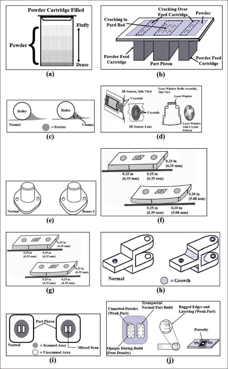
Powder fluff is a frequent challenge in the SLS process. It occurs when the powder at the bottom of the feed-powder cartridge has a higher packing density than the top, leading to uneven powder distribution, as shown in Figure 4a. Furthermore, insufficient powder feeds at the beginning of the build process cause non-uniform powder consolidation, which negatively impacts part quality. Aldahsh 36 suggest that compressing the powder with a flat plastic sheet or a heavy cardboard plate is an effective solution to minimize powder fluff and enhance the overall quality of fabricated parts. To overcome the powder fluff, the powder must be pre-dried to avoid moisture and sieved to remove sintered agglomerates. 37 If required, virgin powder can be added in an appropriate proportion to improve its flowability. The speed of the recoater should be optimized to prevent aeration during SLS. Similarly, the gap between the recoater and powder layer should be adjusted in such a way that uniform powder spreading is achieved without disturbing the previous layer.38, 39 Now, forward rollers are prescribed to spread and compact the powder during the SLS process. Sometimes, the use of a forward roller is limited in the case of a large part or inferior powder flowability. In such cases, several advanced recoating techniques, such as hybrid recoaters (a combination of forward and backward rollers or a combination of forward roller with blade), are preferred to spread and compress the powder. 40
Source: Redrawn based on data from DTM Corporation, 1996, DCN:8001-10003. 59
Cracking of part-bed and feed-cartridge
Due to the high heating rate from the part-bed and feed-heaters, partial melting of the powder can occur on the surfaces of both the part-bed and feed-cartridge. As the roller moves across these areas, cracks may develop, as illustrated in Figure 4b. To mitigate this issue, Aldahsh 36 recommended gradually lowering the temperature set points of the part-bed and feed-heaters in increments of 2°C until the cracks are no longer visible.
Clumping
The accumulation of powder in front of the roller as it moves across the part-bed surface is known as clumping. This issue results in the formation of streaks or cracks on the powder bed, which become visible behind the roller, as shown in Figure 4c. Clumping occurs due to several factors, including moisture in the powder, the use of recycled or overheated powder in the feed cartridges, and inadequate sifting. To mitigate this problem, the temperature settings of both the left and right feed-heaters are lowered, and recycled powder is thoroughly sifted before reuse to ensure better powder distribution and prevent agglomeration.
Crystals and condensation
Excessively high part-bed temperatures can lead to the vaporization of volatile materials during processing, resulting in the formation of crystals or condensation on the lens of the IR sensor, as illustrated in Figure 4d. This crystal buildup interferes with accurate temperature readings of the part-bed and can hinder the proper melting and escape of powder, leading to defects in the final part. Additionally, if crystals form on the laser window, they can reduce the laser power reaching the part-bed surface, causing weak or curled parts. To address this issue, the IR sensor and laser window should be cleaned before initiating the part-building process, but not during each build. Once the build begins, no corrective actions are recommended.
Bonus Z
Aldahsh 36 described the Bonus Z phenomenon in the AM processes. This occurs when the laser melts a part beyond the intended depth (approximately 0.004 inches or 0.1 mm) during the initial scans, leading to unintended vertical growth along the Z-axis. Unlike general part growth, which can appear on any part edge, Bonus Z specifically affects downward-facing surfaces, as illustrated in Figure 4e. The phenomenon arises due to the diffusion of unsintered powder beneath the part boundary when exposed to the laser, causing the part dimensions to exceed the specified Z-axis tolerance. To mitigate or eliminate Bonus Z, adjustments can be made by reducing the laser exposure time, thereby lowering the temperature in relation to the powder bed temperature. Additionally, decreasing the fill-laser power for the initial layers (typically the first to fourth layers) can help control excessive melting. Another effective approach involves applying a constant Z-dimension offset in the STL file, ensuring that only downward-facing surfaces shift upward according to the predefined offset value.40, 41
Curling “in-build”
Curling “in-build” refers to a condition where the edges or corners of a part extend beyond the powder bed surface during fabrication. This issue can cause parts to become narrower along the Z-axis, as illustrated in Figure 4f. Curling primarily results from temperature variations, occurring when the part temperature drops significantly after the addition of feed powder or when the part-bed temperature is too low. 43 This leads to the production of uneven or non-flat parts, especially in sections with large surface areas. In severe cases, curling may cause the part to approach the part-bed while the roller moves over it. To address this issue, the set point values for the left and right feed-heaters should be raised to the highest possible temperature while ensuring the powder remains free-flowing. Additionally, increasing the powder bed temperature helps reduce heat loss from the build to the powder bed. It is suggested that decreasing the distance between the left and right feed areas can further minimize curling during the build process. 36
Curling “post-build”
Curling “post-build” occurs when a fabricated part is not entirely flat, even though its Z-dimension remains accurate. This issue, illustrated in Figure 4g, is primarily caused by rapid cooling, where the heater temperature drops too quickly, or the part is removed from the process chamber prematurely. As a result, the part may warp, particularly in sections with large surface areas, despite maintaining the correct Z-dimensions. To address curling “post-build,” Aldahsh 36 and Tiwari et al. 8 suggested increasing the left and right feed temperatures along with the powder bed temperature. Additionally, to prevent warping, parts should be allowed to cool gradually within the SLS machine before being removed. Once taken out, they should be left to cool completely outside the machine to ensure dimensional stability.
Growth
The growth phenomenon refers to the unintended sintering of excess powder onto a fabricated part, leading to dimensional changes. This issue is particularly noticeable in fine details or small apertures and can occur along any part edge, as illustrated in Figure 4h. The primary causes of growth are excessive laser power and high part-bed temperatures, which result in heat diffusion beyond the intended part boundaries. This leads to oversized parts that may be difficult or even impossible to separate from the surrounding powder. To mitigate growth, corrective measures include reducing the part-bed temperature and lowering the fill-laser power to prevent excessive heat diffusion. 36
Missed-scan
The missed-scan issue in the SLS process occurs when the laser beam fails to completely scan the fill area of a part, as illustrated in Figure 4i. This problem typically arises due to errors in the STL file, where the CAD model contains improperly connected surface patches, leading to incomplete scanning. Although the missed-scan phenomenon is not material-dependent, it significantly affects part quality, resulting in incorrect geometry and poor mechanical properties. Dimov et al. 44 suggested that this issue can be resolved by ensuring the use of correctly formatted STL and CAD files or by generating new files with properly connected surface patches to prevent scanning errors.
Weak parts/porosity
The issue of weak parts and porosity arises when a fabricated part has low density and is brittle, as illustrated in Figure 4j. This problem is primarily caused by an obscured laser window due to crystal formation, leading to insufficient laser power. Additionally, excessively high laser scanning speeds can contribute to inadequate sintering, resulting in reduced part strength and density. 8 To address weak parts and porosity, several corrective measures can be implemented, such as: (a) Cleaning the laser window to ensure proper energy transmission, (b) Increasing the fill-laser power during the build process, (c) Raising the part-bed temperature to enhance powder fusion, and (d) Reducing the laser scanning speed to allow better material bonding. By applying these adjustments, part density and mechanical strength can be significantly improved.
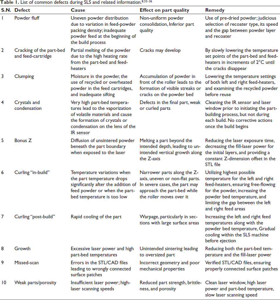
A list of all the frequent defects occurring in the SLS process is listed in Table 1. Table 1 also includes the likely source of defect, its influence on part quality and the plausible remedy to overcome those issues. Further, the above discussion clearly highlights that both over- and under-heating may cause certain defects in the SLS product.14, 16 Therefore, a narrow thermal window exists that corresponds to an optimized temperature range for preventing SLS defects. The processing temperatures below this thermal window may induce incomplete fusion, high porosity, and weak interlayer bonding results. In contrast, temperature exceeding the upper limit may cause excessive growth, melting, grain coarsening, distortion, surface instability, etc. The thermal window balances energy input, heat dissipation, and material response, thus ensuring sufficient fusion while maintaining dimensional accuracy, mechanical properties and part quality.
Recent advances and future opportunities in SLS
Recent advances with regard to the improvement of part quality during SLS have been made by optimizing process parameters, involving machine learning (ML) and in situ monitoring tools, and integrating simulations and modeling techniques. A detailed discussion is provided in the further subsections.
Process parameter optimization techniques
Polymer SLS, particularly of PA12, demonstrates strong sensitivity to process variables such as laser power, scan speed, hatch spacing, layer thickness, and energy density. Pilipović et al. 33 shown that these parameters directly influence flexural and tensile properties by controlling powder fusion and interlayer bonding. Consequently, mathematical models have been proposed to guide parameter selection for improved mechanical performance.
The most impactful finding of this review is that integrating ML with optimized SLS process parameters and in situ monitoring can significantly enhance part quality, mechanical performance, and process reliability. Yehia et al. 45 highlighted the relationship between SLS process variables, such as laser power, scan speed, layer thickness, bed temperature, etc., and part quality in terms of density, porosity, strength and surface roughness. This study also emphasized that the challenges in polymer SLS with regard to part quality are closely linked to thermal control and powder consolidation behavior. They stressed the adoption of ML as a complementary tool for parameter optimization, especially when hardware-level process adjustments are limited. In a separate study, Der and Basar 46 employed TOPSIS (known as Technique for Order of Preference by Similarity to Ideal Solution) to achieve significant improvement in the surface properties during the laser cutting of FFF-printed PLA parts.
In situ monitoring and closed-loop control
Recent studies on SLS emphasizes particularly on in situ process monitoring to overcome the issue of variability in part quality and performance. Wroe et al. 47 used infrared thermal imaging to record layer-by-layer temperature fields during SLS and directly correlate local thermal histories with tensile strength, fracture behavior and interlayer bonding in PA12 parts. In general, non-uniform thermal conditions are considered as a primary source of porosity and weak bonding, establishing real-time thermal data as a critical indicator of part quality. Because thermal and optical imaging can be used only for monitoring the surface, Gardner et al. 48 integrated optical coherence tomography (OCT) with SLS systems to enable subsurface and cross-sectional monitoring during fabrication. OCT provides high-resolution, depth-resolved information on sintering uniformity and energy input errors, offering insights inaccessible to conventional monitoring methods. Such in situ approaches have the potential to develop closed-loop control strategies aimed at correcting defects during the build process.
ML for defect detection and quality prediction
ML has emerged as an important tool for automated defect detection in SLS.49–51 Neural networks have been successfully applied to powder bed images to classify defects such as powder irregularities and surface disturbances. In fact, Westphal and Seitz 49 applied transfer learning approaches and attained accurate classification even with limited datasets, demonstrating feasibility for real-time, non-destructive quality monitoring in SLS environments.
Beyond defect identification, ML methods are also being used to predict the mechanical properties of SLS parts.50, 52 Rodríguez et al. 50 utilized regression-based models to accurately estimate the ultimate tensile strength and breaking strength of PA12 specimens based on tensile load-displacement data, significantly minimizing the need for extensive destructive testing. In addition, the use of multi-modal data further improves predictive performance, reinforcing ML as a practical tool for SLS quality control and process optimization.46, 52
Despite significant improvement in the predictive ability, the industrial adoption of ML tools is limited due to the black box nature of their algorithms. Hence, efforts are underway to develop explainable artificial intelligence (XAI) tools for defect prediction in SLS. 53 For instance, Yu et al. 54 used the Shapley Additive Explanations (SHAP) technique for hardness prediction for titanium alloy. Similarly, Maitra et al. 53 used the Local Interpretable Model-agnostic Explanations (LIME) model for predicting mechanical properties. For the non-metals, Mishra et al. 55 compared several ML algorithms for PLA12 material and eventually recommended the XGBoost algorithm for predicting surface quality. Ukwaththa et al. 56 reviewed use of several XAI methods (SHAP, LIME, feature importance analysis, etc.) and discussed their benefits over typical ML techniques. Apart from predicting defects, for example, porosity, warping, incomplete fusion, and surface roughness deviations, etc., these XAI tools also explain and quantify the contribution of various parameters to the forecasted defect. Thus, XAI enables both root-cause analysis of defects and real-time optimization of SLS process parameters.
Modeling and simulation of SLS processes
Modeling and simulation remain essential for understanding the multi-physics nature of SLS. 57 Now, simulation efforts complement in situ monitoring and ML by providing mechanistic insight into SLS-specific process–structure–property relationships. Papazoglou et al. 58 reported the use of finite element methods, discrete element methods, smoothed particle hydrodynamics, and molecular dynamics to model heat transfer, powder behavior, residual stresses, and part deformation. As per them, heat transfer modeling forms the foundation of most SLS simulations, with additional sub-models introduced as needed. Overall, the literature highlights the absence of a unified SLS modeling framework and stresses the need to balance model fidelity with computational cost.
Future directions and opportunities
In general, SLS is well-known for its ability to reuse unsintered powder, contributing to reduced material waste compared to other manufacturing processes. However, there is a major scope to make the SLS process more sustainable by improving material efficiency, waste reduction, and process optimization. Therefore, future research in SLS is strongly oriented toward closer integration of in situ monitoring, data analytics, and process control. The literature consistently identifies the transition from passive monitoring to active, closed-loop control as a critical next step, where real-time thermal or subsurface measurements are directly used to adjust process parameters during fabrication to mitigate defects and ensure consistent part quality.47, 48 Achieving this integration requires robust sensing, fast data processing, and reliable control strategies tailored to the layer-wise nature of SLS. ML is expected to play an increasingly central role in future SLS development. Recent studies and reviews emphasize the need to move beyond isolated ML models toward comprehensive frameworks that combine in situ sensor data, process parameters, and mechanical performance metrics.49, 50 Such approaches aim to enable real-time defect prediction, adaptive parameter optimization, and reduced reliance on destructive testing, while also addressing current challenges related to data availability, model interpretability, and generalization across materials and machines.50, 52
Advances in modeling and simulation are also identified as a key future direction. The literature highlights the need for more efficient and scalable multi-physics models that can capture heat transfer, powder behavior, and resulting part properties with manageable computational cost. Improved coupling between simulations and experimental data is emphasized as a pathway to enhance predictive accuracy and support process optimization, particularly when combined with ML and in situ monitoring data. 58
Overall, the future trajectory of SLS research converges on data-driven manufacturing, where sensing, ML, and simulation are integrated to improve reliability, reduce waste, and enable consistent, application-ready polymer parts. These directions reflect a shift from empirical parameter tuning toward systematic, adaptive, and digitally supported SLS process control.
Summary and conclusions
AM faces several key challenges that hinder its widespread adoption. Limited fabrication speed and consistency across technologies, along with constraints in product quality and aesthetics, often restrict output reliability. High costs of AM machines, coupled with the need to improve cost-effectiveness and energy efficiency for large-scale production, make scalability difficult. Enhancing AM’s capability to integrate functional materials remains a hurdle, as does the lack of awareness about its environmental impact and disruptions in material supply chains.
Further obstacles include limited automation in processes, the need for certification, and establishing mandatory standards and regulations to ensure quality control—especially in distributed manufacturing networks where maximizing machine utilization is essential. Seamless integration with hybrid technologies in design and production requires educating designers and engineers on AM’s advantages, while expanding access for prosumers through home-based applications demands better efficiency in the build process. Limited availability and high costs of digital design resources exacerbate these issues. Addressing these challenges will be crucial for the broader adoption and efficiency of AM technologies. Moreover, integration of modern tools such as ML, closed-loop monitoring, simulation and modeling, etc., is critical to enhance the part quality during SLS fabrication of parts.
Footnotes
Declaration of Conflict of Interests
The authors declared no potential conflicts of interest with respect to the research, authorship, and/or publication of this article.
Funding
The authors received no financial support for the research, authorship, and/or publication of this article.