
Abstract
Quartz possesses distinct characteristics such as exceptional hardness, high brittleness, non-conductivity, remarkable corrosion resistance, efficient transmission within specific wavelengths, strong electrical insulation properties, and the ability to withstand high temperatures and thermal shocks. These extraordinary attributes have led to its component in a wide range of applications, including the fabrication of microelectronic chips, biochips, biological channels, microfluidics, optical lenses, beam-splitting lenses, etc. Ultrasonic micromachining (USMM) is a highly promising technique within the realm of micromachining to create micro features on quartz surfaces. In the present research, array of square micro tools has been designed and developed by the wire-electrical discharge machining (EDM) process. By utilizing the developed array of square micro tools, microcavity arrays have been generated by the USMM process. The influences of process parameters on material removal rate (MRR), width deviation (WD), angular deviation, and taper of square microcavities have been investigated in the present research work. The higher MRR is obtained as 1.427 mm3/min at higher abrasive slurry concentration and lower WD of micro cavities is obtained as 37 µm and lower taper angle is 1.109° at 5% abrasive slurry concentration. The lower value of angular deviation is obtained as 0.836° at a lower power rating during the generation of an array of square microcavity on quartz by the USMM process. By employing array of micro tools, the accuracy of micro features can be improved, and also productivity can be increased.
Introduction
Quartz has unique properties like high hardness, extremely brittleness, non-conductivity, extremely corrosion resistance, superior high electrical insulation properties and outstanding resistance to high temperatures and thermal shock resistance, etc. Due to such unique properties, it is comprehensively used in the fabrication of microelectronic chips, biological microchips, biological conduits, micro-fluidic channels, lenses for optics, lenses, etc.1, 2 From experimental observation, it is identified that ultrasonic micromachining (USMM), is best suited for a precise and accurate array of square shaped microcavity generation on quartz. As quartz is a transparent and electrically nonconductive material; electrical discharge machining (EDM), electrochemical machining (ECM) is unable to machine quartz. Laser beam machining has some thermal effects during the machining of quartz. Various non-traditional machining techniques like laser beam micromachining, 3 chemical etching, and micro-abrasive flow machining4, 5 are used to fabricate micro features on quartz. Still, these non-traditional machining techniques have some limitations. Laser beam micromachining of glass may occurs micro-cracks, poor machined surface, and recast layer. 6 Chemical wet etching utilizing multilayer masking to produce micro features with good surface on glass, but complicated masking methods and use of chemicals like HF and HCl is very hazardous also it requires long productivity time. 7 Due to such limitations, micromachining with a tool-based method garnering attention to produce micro features on glass.8, 9 Reverse engineering method was used to developed a tool for USM from the measurement data of the existing machined cavity. The developed tool was also tested for generating hemispherical cavities on zirconia and well accepted with high accuracy. 10 Micro-USM process represents a mechanical type tools-based micromachining process that is used to produce micro features on glass. 11 USMM is also a widely recognized micromachining technique that is increasingly being embraced for its ability to fabricate complex and complicated micro features on a variety of challenging materials. This includes harder ceramic materials such as glass, quartz, and composites, as well as tougher materials like titanium and its alloys. 12 Micro ultrasonic machining (µ-USM) using a tool that vibrates ultrasonically. Abrasive particles are suspended in liquid and continuously supplied between the tool and workpiece. Micro-USM closely resembles stationary USM, differing primarily in tool size, abrasive size, and the amplitude of vibration, all of which fall within the micro range. 13 In µ-USM, the abrasive slurry flows through the machining zone and penetrates the work surface again and again by vibrating tool, and the material is removed by brittle fracture. It is quite different from other micromachining processes like EDM, laser beam machining (LBM), and ECM because no thermal, chemical, and electric phenomenon occurs in the micro-USM process. This unique quality makes it an effective machining process for fabricating intricate micro features and parts, especially on hard and brittle materials. These are some different use cases where micro USM has shown its impeccable capability. A micro hole and micro 3D cavity was generated on silicon by µ-USM. 14 A mathematical model was developed to express the material removal process in µ-USM and also validated by the experimental results. 15 Micro hole drilling was done on CFRP/Ti by conventional micro drilling and micro-USM process. The results revealed that the µ-USM process produced better hole quality with zero delamination at the entrance surface of the hole. 16 Blind micro hole was successfully generated on silicon and it was concluded that machining speed was decreased at a certain level and gathering of debris during machining was the main cause of low machining speed. 17 A new method known as chemical-assisted ultrasonic machining was introduced to get better machining efficiency and better-machined surface of the glass. In this method, a dilute solution of “hydrofluoric acid” was introduced into the Al2O3 slurry for enhancement of material removal rate (MRR) and surface finish of the machined surface. 18 Ultrasonic machining operation was performed to generate a noncircular hole on Al2O3. The effect of process variables such as abrasive size, tool feed rate (TFR), slurry concentration, and power rating on machined profile accuracy was examined. 19 Micro tools were fabricated using wire-electro discharge grinding (EDG). The further fabricated tool was used to produce micro holes on glass and it was reported that there were no fractures and cracks at a depth of cut 0.05 µm. 20 Abrasive particles were distributed in a random way in the machining area and their movement affected the machined profile accuracy. Abrasive distribution established a close relationship (convex or concave) with machined profile accuracy. 21 Micro-USM was used to generate circular micro holes on quartz using three different abrasives such as B4C, SiC, and Al2O3 of the same grit size. It was concluded that Al2O3 abrasive was appropriate for good geometrical accuracy. 22 A new method was presented for understanding the nature of the mechanism of USM by employing a simulation called SPH and FEM. SiC and Al2O3 abrasives of different shapes were integrated in the simulation to understand the fracture procedure of the workpiece as well as abrasives. The best machining result was obtained from experiments as well as simulation by selecting spherical Al2O3 abrasive particles. 23 The research focused on exploring the micro-drilling characteristics of Al-PE laminate composites by employing Taguchi L16 orthogonal array and ANOVA analyses. The study specifically examined key factors such as thrust force, exit burr height, and hole diameter. Important findings highlighted the considerable influence of the tool’s point angle on thrust force and burr height, the role of cutting speed in controlling hole diameter during micro drilling. 24 Various conventional and non-conventional machining processes were used for drilling micro holes on a wide variety of materials. Among the various processes, the USMM process is the best option for obtaining high-quality holes with different tool types and sizes, especially for materials of hardness of more than 40 RC. 25
Based on the literature review, it was found that the majority of the research work was done by a single tip tool of the circular cross-section for drilling operations. It hampers the accuracy of micro holes by repetitive use of the same tool during successive machining and also takes more time for the operation. To solve this problem, an array of micro tools has been designed and developed by the wire-EDM process. By utilizing the developed array of micro tools, a micro square cavity array has been generated by the USMM process. The array of square microcavity on quartz has a versatile set of applications in biomedical science, MEMS, telecommunications, precision sensing, and bio-sensing, micro-fluidics and lab-on-a-chip devices, microfiltration, optical components, photonics, etc. The generation of an array of square microcavity on quartz is very much needed utilizing the array of micro tools in the USMM process to save time and obtain good accuracy. In this current research, we have examined how various process parameters affect the MRR, width deviation (WD), angular deviation, and taper of square microcavities. This investigation aims to establish the applicability of a micro tool array in USMM.
Materials and methods
In the current study, experiments were conducted for the development of an array of micro tools and the generation of an array of square microcavities on quartz utilizing the developed array of square micro tools by USMM.
Design and development of array of micro tool
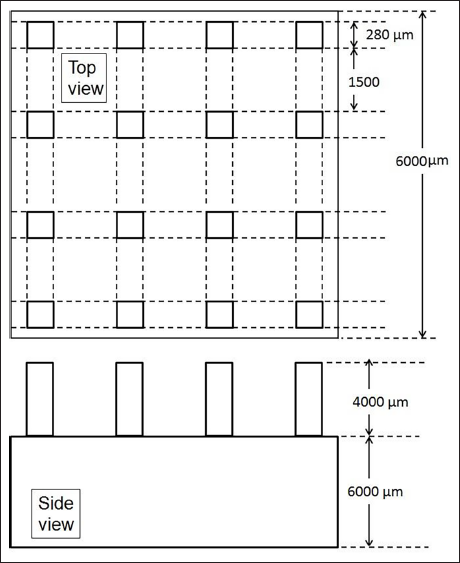
The development of microtools is one of the vital tasks for tool-based micromachining. To complete this task, a detailed understanding of the design and specification of micro-tools, like tool dimension, length, weight, and materials, along with the capabilities, advantages, and limitations of various tool fabrication techniques, is necessary. Figure 1 shows the layout and dimensions of the micro tool array. To fabricate the micro tool for USMM, various methods like reverse EDM, reverse ECM, and wire EDG are used. Reverse-EDM and Reverse-ECM are processes utilized to fabricate circular tool-tips and these are best suited for tools with low aspect ratios. Reverse-EDM was used to fabricate multiple cylindrical microtool electrodes of length 1.5 mm and diameter 35 µm from WC rods of diameter 300 µm, which took about 30 min. 26 Micro-tools fabricated by Reverse-EDM have also some taper errors. 27 Wire-EDG process is renowned for the fabrication of circular and single-tip cylindrical tools. The wire-EDM process is primarily utilized for fabricating array microtools.28, 29 Considering the limitation of the above-mentioned process, wire-EDM was chosen for fabricating the array of square micro tools. This method generates a sequence of sparks between the workpiece (anode) and the moving wire (cathode) while maintaining continuous flushing. Consequently, throughout the machining procedure, the wire electrode and the workpiece remain separated by a dielectric medium, ensuring that there is no direct contact between them. This separation effectively eliminates any induced mechanical stress on the developed tool array during the machining process. Hence, wire EDM is used over other techniques for the fabrication of an array of microtips tools. For fabrication of an array of micro tool wire-EDM (EX-40 WEDM) was used. Copper wire with zinc coated having a diameter of 250 µm was utilized as an electrode for wire-EDM. Deionized water was utilized as dielectric, with precise temperature control at 21°C. To ensure optimal dielectric flow, both the upper and lower flushing nozzles were fully opened. At first, the stainless steel (SS304) bar of square cross-section was clamped into the work table of wire EDM. Then it is cut into two steps. After the first cut work piece is rotated into 90°. Figure 2(a) shows a schematic view of an array of square micro tools and Figure 2(b) optical view of the micro tool array developed by wire cut EDM process. Each tooltip consists of a square shape of 280 × 280 µm2 cross-section and 4,000 µm height.
Micro tool array design with dimension.
(a) Schematic view of array micro tool and (b) optical view of array micro tool.
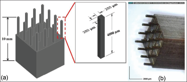
The primary objective of designing array micro tool dimensions that will be suitable for the USMM system. Authors have tried to fabricate minimum tool dimensions as well as equal dimensions of all tooltips and gaps between tips which can be generated by WEDM and utilized in the USM system for better availability of abrasive slurry in turn generation of an array of square microcavities on quartz. The aspect ratio of multi-tip micro tool is obtained as 14. The aspect ratio of the micro tools affects the machining performance. If the aspect ratio of micro tools is decreasing, the flow of abrasive slurry will not be proper in the gap between the tips of micro tools. If the aspect ratio of the micro tool is increasing, it affects the stability of the micro tool. Therefore, the aspect ratio is selected as 14 based on the experimental observation in terms of MRR, WD, angular deviation, and taper of square microcavities. The utilization of a 4 × 4 array micro-tool results in reduced machining time, serving the purpose of swiftly validating batch fabrication concepts. The square micro-tool array can be scaled up to larger sizes for the generation of more number of square microcavities within less period of machining time. However, the development of an array of micro tools of large number of tips is a challenging task for scaling up the process of generating more square microcavities in less time. The productivity of the micro USM process increases as more number of cavities is generated at a single run. It is also important to maintain consistent dimensions, tolerances, and geometries across a large number of tooltips for controlling precision and quality.
Experimental setup details and planning
Experiments were conducted using “AP sonic mill 1000” for the generation of array of square microcavities on quartz. The USMM technique involves applying mechanical vibrations at an ultrasonic frequency, approximately 20 kHz, to the micro-tool, which vibrates with low amplitude. A mixture of irregularly shaped abrasive and water is introduced into the space between the micro-tool and the workpiece. During USMM, the vibrating tooltip comes into contact with loose abrasives present in the slurry, causing these abrasive particles to gain momentum and impact forcefully on the surface of the target workpiece. Material removal takes place in the impact zone through sustained hammering and micro-chipping, which is a result of mechanical abrasion by the hard micro-abrasive particles. 11 To facilitate the machining process, the nonstop slurry is supplied between the workpiece and the tool, serving two primary purposes: first, to clear debris from the machining zone, and second, to replenish the gap with fresh slurry, thus maintaining the efficiency of the process. Figure 3 illustrates the schematic diagram of the USMM setup.
Schematic diagram of ultrasonic micromachining (USMM) setup.
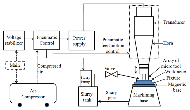
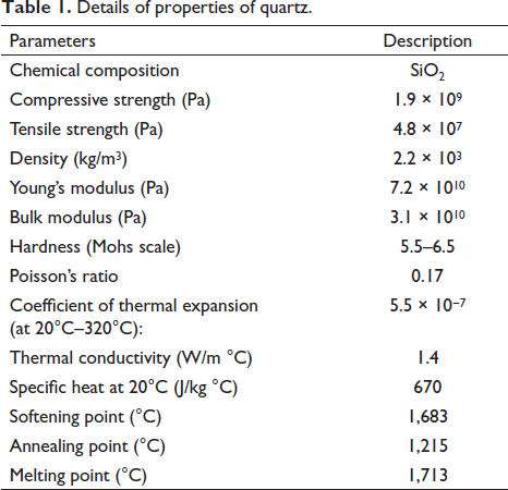
After the development of the multi-tip micro tool, it is silver brazed with a tool holder. The tool holder is fixed on the horn with a screw fitting. The square quartz workpiece plate of size 25 mm × 25 mm × 2 mm was fixed on the fixture using wax. The details of the properties of quartz are given in Table 1. The fixture is further fixed at the magnetic machining base. The initial inter-space between the micro tool and the work surface is set by a micrometer. Al2O3 abrasive has less hardness compared to SiC and B4C. In µ-USM, precise material removal and control are essential. Using Al2O3, which is less hard and brittle compared to B4C and SiC, which reduces the risk of causing micro-cracks or microchipping in the quartz material during machining. A smoother surface finish is observed using comparatively less hard abrasive like Al2O3 during machining quartz. This is important in micromachining applications where achieving precise surface quality and minimizing subsurface damage are essential. Quartz, being a crystalline material, can be more sensitive to abrasive hardness. Softer abrasives like Al2O3 are often chosen to reduce the risk of introducing defects or damaging the crystal structure of the quartz during machining. Al2O3 is also being liable to be more cost-effective compared to B4C and SiC. In certain applications, especially when the cost of consumables is considered then the use of Al2O3 can be a deciding factor during machining of quartz. The average size of Al2O3 abrasive particle is 4 µm. Liquid media, namely water, is employed in combination with abrasive. Water present in the abrasive slurry acts as a coolant during the USMM process. The striking of abrasives on the workpiece with ultrasonic vibrations generates a little heat at the tool-workpiece interface. The abrasive slurry helps dissipate this heat, preventing the tool and workpiece from overheating. The slurry absorbs some of the heat energy and carries it away, helping to maintain lower temperatures at the machining zone. The slurry also helps in flushing away these debris particles from the machining zone, preventing them from re-entering and interfering with the machining process.
Details of properties of quartz.
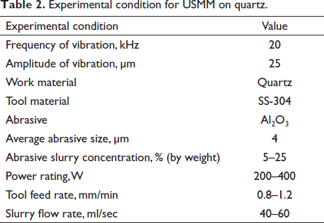
In the USMM process, the key process parameters include the power rating, concentration of abrasive slurry; TFR, and slurry flow rate. The concentration of abrasive slurry ranges from 5% to 25% by weight, the power rating ranges from 200 to 400 W during experimentation, the TFR varies from 0.8 to 1.2 mm/min in experimental settings, and the slurry flow rate modulated within the range of 40–60 ml/sec. The parameters range for the generation of square microcavities on quartz is determined based on basic experiments on quartz and literature review. Table 2 represents the experimental conditions of USMM for fabricating an array of microcavities on quartz.
Experimental condition for USMM on quartz.
Measurement of responses
The measurement procedure and calculations of responses such as MRR, WD, angular deviation, and taper angle are described in the subsequent subsections.
Measurement of material removal rate
The width of the entrance surface of the square microcavity is measured by an optical measuring microscope. The width is taken at both sides of all micro holes and the average width is calculated. The MRR is calculated using the following equation:
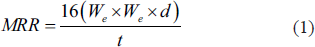
where We and d are the average the width at entrance and depth of square microcavity, respectively, which are illustrated through the diagram as shown in Figure 4 and t is the time taken for generating an array of square microcavity on quartz.
Schematic view of an array of the micro holes.
Measurement of width deviation (WD)
To determine the WD along the flat surfaces of the square microcavity, one can measure the distance between the flat surfaces on both sides of the square microcavity. The difference of measured average width along flat surfaces of microcavity on machined quartz workpieces and an average width of the utilized array of square micro tooltips will give WD. The width is taken at the entrance of square microcavities on both sides and so for a single machining operation, the width is the average of 32 measurements of 16 numbers of square microcavities. After the measurement of WD of square microcavity and width of square micro tooltip, WD is calculated by using the following equation:

where We average width at entrance of square microcavity on quartz workpiece and Wt is the average width of the square micro tooltip.
Measurement of angular deviation
The angular deviation at the corners of the square microcavity is determined by comparing the experimentally observed angles (in degrees) at all corners of the cavity with the angles of the microtool’s corners. This deviation for a specific machined corner is derived from the difference between the experimentally determined angles of the workpiece and the angle at the tool’s corner. The values of angular deviations (DA) for square microcavity were assessed by averaging the angles of all four corners of the machined micro holes.
Measurement of taper angle
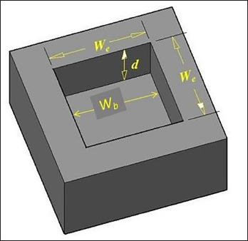
Following the measurement of the average width at the top and bottom surfaces of the microcavity, the half-taper angle is determined using Equation (3) which is represented in Figure 5.

where We is the average width of square microcavity at the entrance surface, Wb is the average width of square microcavity at the bottom surface, α is the taper angle and d is the depth of square microcavity on quartz.
Taper representations in microcavity.
Results and discussion
In this study, array of square micro tools has been designed and developed to fabricate the square microcavity array on quartz. During machining on quartz one factor at a time has been varied and other factors are kept constant at a medium level to study the influence of the USMM process. The other factors are kept at a medium level because it prevents the cracks propagation on the workpiece surface. The influence of process parameters of square microcavity array on quartz has been discussed subsequently.
Influence of power rating on MRR, WD, angular deviation, and taper angle
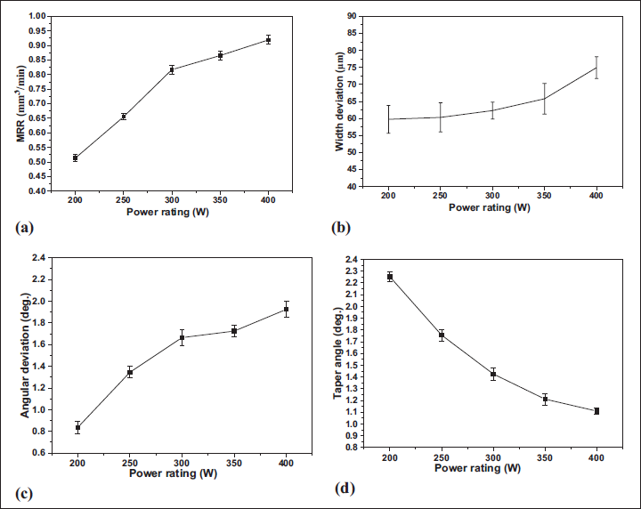
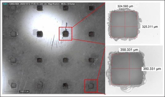
The ultrasonic power has a considerable effect on the MRR, WD, angular deviation, and taper angle of square microcavity produced on quartz. At the same time, other parameters including tool feed rare, abrasive slurry concentration, and slurry flow rate are fixed at 1 mm/min 15%, and 50 ml/sec, respectively. Figure 6(a) shows, how the MRR, varies with power rating. The lower MRR of 0.50 mm3/min was recorded for a power rating of 200 W which is much more than the higher MRR, that is, 0.198 mm3/min obtained by another researcher. 30 The MRR is affected significantly by the ultrasonic power. Increasing the power supplied to the ultrasonic transducer results in faster movements of the tool, which in turn increases the velocity. This higher velocity translates to an increase in the kinetic energy of the abrasive particles. This high energy transfer leads to more efficient material removal when abrasive particles impact on the workpiece surface, contributing to enhanced machining capabilities. From the figure, it is also clear that the MRR increases rapidly as the ultrasonic power is increased from 200 to 300 W and then increases slowly to 0.920 mm3/min at a power rating of 400 W. Initially when the ultrasonic power is increased from 200 to 300 W, it causes more effective and efficient removal of material due to increased vibration energy. This leads to a rapid increase in MRR as more material is being removed. At higher power levels, that is, after 300 W, there will be wear of the tool due to striking of abrasive with high momentum on the tool, affecting the machining process and the rate of increase of MRR from the workpiece becomes less. Additionally due to tool wear, the flatness of the bottom surface of the tooltips changes which also results in a lower rate of MRR. The effect is due to an increase in power rating, the abrasive particle strikes with more energy during the array of microcavity processing. Figure 6(b) illustrates the effect of power rating on WD of square microcavity produced on quartz. The lower WD has been observed as 59 µm at a 200 W power rating. As the power rating increases, the abrasive particles smack with higher striking energy, is forming larger indentations. Consequently, a greater amount of material is removed from the work surface, leading to an increase in WD of square microcavity. From the experiments, it has been noted that the higher WD is 75 µm at 400 W. The standard deviation of WD is higher due to the generation of more cavities in a single operation. The outer cavities situated at the periphery of a 4 × 4 array of square microcavities exhibit greater WD in comparison to the inner cavities as shown in Figure 7. This due to the non-uniform availability of abrasives at all the tips of the micro tool. It can be eliminated by utilizing the proper flow of abrasive slurry within all the tips of the micro tool.
Influence of power rating on (a) MRR, (b) width deviation, (c) angular deviation, and (d) taper angle.
Periphery of the array has more width deviation compared to the inner holes.
The influence of power rating on angular deviation is shown in Figure 6(c). The smaller angular deviation has been observed at a lower power rating. Angular deviation has been gradually increases with the increase in power rating. It has been noted that angular deviation changes from 0.8366° to 1.925° while power rating changes from 200 to 400 W. Figure 6(d) illustrates the results of power rating on the taper of square microcavity on quartz. Higher taper is observed at lower power rating and it decreases with the increase in power rating. This is attributed to the higher kinetic energy of abrasive particles resulting in a higher cutting rate. As a consequence materials are uniformly removed from the bottom part of the square microcavity, leading to reduced taper at higher taper ratings. Specifically, at power ratings of 200 and 400 W, taper angles of 2.252° and 1.11° are obtained, respectively.
Influence of abrasive slurry concentration on MRR, WD, angular deviation, and taper angle
The influences of slurry concentration on USMM process criteria during the generation of square microcavity on quartz utilizing an array of micro tools have been discussed in this section. At the same time keeping other parameters constant, that is, power rating of 200 W, TFR of 0.8 mm/min, and slurry flow rate of 40 ml/sec. Abrasive particles are primarily responsible for removing the material from the workpiece and the MRR depends on both the amount of abrasives used in the machining process and the unit removal volume per particle, both of which are influenced by slurry concentration. The effect of abrasive slurry concentration on MRR during the array of micro square cavity generation on quartz has been shown in Figure 8(a). From the findings of experiments, it has been noted that MRR significantly changes from 0.806 to 1.427 mm3/min with the change in slurry concentration from 5% to 25%. Following an increase in concentration, more abrasive is present at the bottom face of micro tool. Due to this, the numbers of impact are more, and hence more materials are removed. The higher MRR achieved during the generation of an array of square microcavity of 16 numbers employing an array of the micro tools is 1.47 mm3/min, which is much higher than that of using a single tip micro tool obtained during the machining of quartz material. From the experimental observation, it is observed that the minimum time required for machining of quartz for achieving a depth of 500 µm with an abrasive slurry concentration of 25%, power rating of 300 W, and TFR of 1 mm/min is 32 seconds. However, if a single microtip tool is utilized for fabricating 16 square holes, it roughly takes 500 seconds, and fabricated micro holes are also not in equal spacing.
Influence of abrasive slurry concentration on (a) MRR, (b) width deviation, (c) angular deviation, and (d) taper angle.
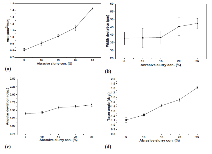
The effect of abrasive slurry concentration on WD of micro square cavities on quartz is also shown in Figure 8(b). It has been observed that abrasive slurry concentration has almost no effect on WD when it changes from 5% to 15%. It is also observed that WD gradually increases while slurry concentration varies from 15% to 25%. After raising the slurry concentration, more abrasives contribute in machining and also these are present near the side wall of the channel. So from the side wall of the channel, more materials are also removed. Hence, the width overcut of the microchannel becomes large. The influence of abrasive slurry concentration on angular deviation during the array of square microcavity generation on quartz is shown in Figure 8(c). It has been observed that angular deviation changes from 1.39° to 1.67° while abrasive slurry concentration varies from 5% to 25%. Higher abrasive slurry concentration typically leads to increased tool wear, due to more abrasive present, thus contributing to higher angular deviation during generation of square microcavities on quartz by micro-USM square microcavity. Figure 8(d) shows the effect of abrasive slurry concentration on the taper of the square microcavity. The lower taper is obtained at a 5% slurry concentration. Taper angle, of square microcavity increases with an increase in abrasive slurry concentration. The taper angle is obtained as 1.109° and 1.512° at 5% and 25% abrasive slurry concentration, respectively. In higher slurry concentrations, the mixture contains a greater amount of abrasive particles combined with water, resulting in more MRR but diminished accuracy.
Influence of TFR on MRR, WD, angular deviation, and taper angle
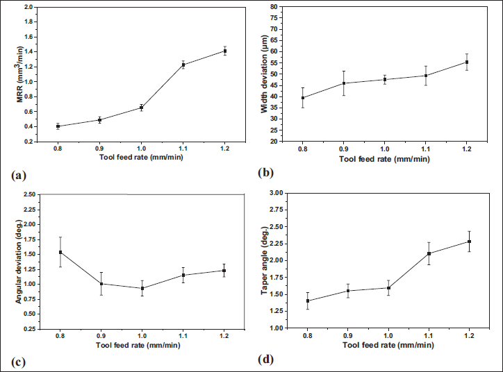
TFR is an important parameter for USMM and it can be defined as tool movement toward a stationary workpiece per unit of time. TFR is a crucial process parameter for µ-USM. The TFR was varied from 0.8 to 1.2 mm/min. The impact of the TFR has been analyzed, keeping other parameters, such as power rating, slurry concentration, and slurry flow rate, constant at 300 W, 15%, and 50 ml/sec, respectively. The influences of TFR on MRR are shown in Figure 9(a). MRR increases slowly from 0.8 to 1 mm/min TFR and then increases sharply. With the increase in TFR, impact force increases, and hence MRR increases. The higher MRR is obtained as 1.413 mm3/min, at 1.2 mm/min TFR. Figure 9(b) shows the influence of TFR on WD. When the TFR is kept low, the abrasive particles strike with relatively small force, resulting in minimal WD. However, as the TFR is raised; the striking force of the abrasive particles correspondingly increases, leading to a higher WD. WD is larger at a higher value of TFR. It was noted that the angular deviation of square microcavity decreases up to TFR 1 mm/min and then increases as shown in Figure 9(c). Using a higher feed rate with the same static force may lead to increased tool wear, so angular deviation is more. Figure 9(d) shows the influences of TFR on the taper of square microcavity on quartz. After increasing TFR, the taper angle is observed as large because at higher TFR, the impact force on work surface increases. Material removed from the top portion of the square microcavity is more since more abrasive particles are available for machining from all side walls of the square microcavity. Due to this, the top width of the cut is more than that of bottom surface of the square microcavity, so taper angle increases. Less taper angle can be achieved at a lower TFR setting. At a TFR of 1.2 mm/min, microcavity has a higher taper angle of 2.27°.
Influence of tool feed rate on (a) MRR, (b) width deviation, (c) angular deviation, and (d) taper angle.
Influence of slurry flow rate on MRR, WD, angular deviation, and taper angle
The slurry flow rate means the abrasive particles per unit of time taking part in machining. The slurry flow rate was varied from 40 to 60 ml/sec. Simultaneously, other process parameters, including power rating, abrasive slurry concentration, and TFR, remain constant at 300 W, 15%, and 1 mm/min, respectively. Figure 10(a) shows the influence of slurry flow rate on MRR. At lower abrasive slurry flow rate, MRR is low, that is, 0.518 mm3/min. With a higher slurry flow rate, MRR becomes more. Due to the raise in slurry flow rate new abrasives involved in machining and also debris particles effectively come out from the gap between the tool and work surface, so MRR increases. At 60 ml/sec slurry flow rate MRR is obtained as 1.2672 mm3/min.
Influence of slurry flow rate on (a) MRR, (b) width deviation, (c) angular deviation and (d) taper angle.
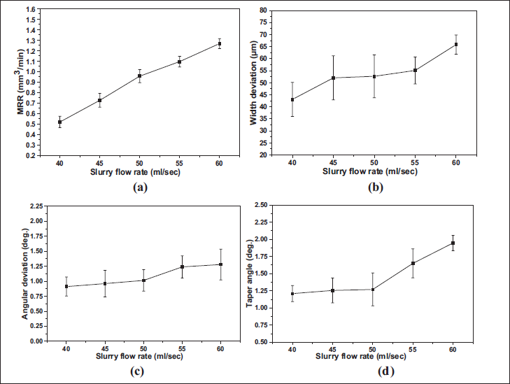
Figure 10(b) shows the influence of slurry flow rate on the WD of square microcavity. WD is taken on both sides of micro holes. At a lower slurry flow rate, WD is low, that is, 43 µm and it increases with an increase in slurry flow rate. At 60 ml/sec slurry flow rate, WD is obtained as 66 µm. By increasing the slurry flow rate, there’s an augmentation in the presence of new abrasive particles positioned between the micro holes side wall and the micro tool. Consequently, this amplifies the side-cutting action, resulting in an escalation of WD within the micro holes. Figure 10(c) shows the influence of slurry flow rate on the angular deviation of square microcavity. The angular deviation is not so much effected by slurry flow rate as observed from the experimental results. The angular deviation is 0.91° at a lower the slurry flow rate and it slowly increases up to 1.28°. Figure 10(d) shows the influence of slurry flow rate on taper of square microcavity. The increase in taper of square microcavity is very less while slurry flow rate varying from 40 to 50 ml/sec. After that, it suddenly increases at higher slurry flow rate. A higher slurry flow rate can result in more aggressive material removal from the entrance region of the hole, leading to a wider entrance compared to the bottom region, causing more taper.
Analysis based on scanning electron microscope (SEM) micrographs
SEM micrograph-based analysis involves the study of visual representations obtained through microscopic techniques are discussed in this section. By studying images captured at a microscopic level, valuable insights can be understood with respect to the structure and characteristics of materials after USMM.
The surface morphology resulting from the machining process was further studied using a SEM. Figure 11(a) shows the scanning electron micrographs of an array of microcavity (4 × 4) produced on quartz by utilizing a developed array of micro tools at 400 W power rating, 15% abrasive slurry concentration, 1.0 mm/min TFR and 50 ml/sec slurry rate. Some edge chipping is observed at the entrance surface of square microcavity which is shown in Figure 11(b) in 500× magnification. Figure 11(c) shows the corner accuracy of square microcavity at 1000× magnification.
SEM image of (a) array of micro holes (4 × 4) on quartz; (b) enlarged view of a single hole at mag. 500×, (c) zoom view at mag. 1000×.
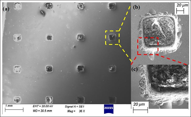
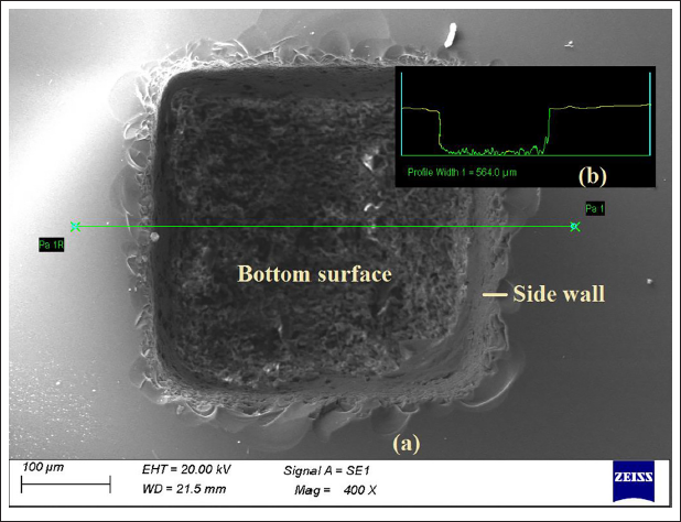
Figure 12(a) shows the microcavity at 400× magnification which revealed that the side wall of hole has a comparatively good surface finish at 5% abrasive slurry concentration, 200 W power rating, 0.8 mm/min TFR, and 40 ml/sec slurry flow rate. Figure 12(b) shows the 2D profile of square microcavity which exhibited to corner accuracy at bottom surface and also machined surface profile at bottom. The surface roughness at bottom surface and side wall is different, it may be due to thermal energy. However, the heat generated between the tool and the work surface is not so much affects the machined surface as water is present in the abrasive slurry which acts as coolant. Bottom surface has more surface roughness because more coarser abrasive particles strike at bottom surface as a result there is an overlapping of comparatively large craters generated at the bottom surface.
SEM image of (a) micro hole on quartz (b) 2D profile of micro-hole at a section.
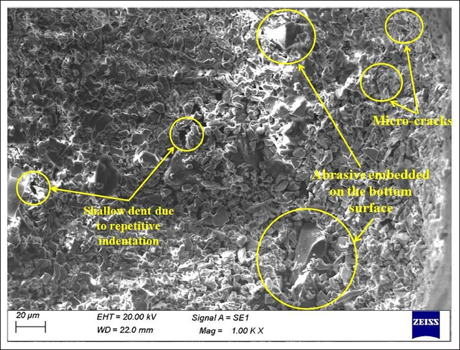
In Figure 13, an SEM micrograph displays the bottom of the machined square microcavity produced through USMM at 400 W power rating, 15% abrasive slurry concentration, 1.0 mm/min TFR, and 50 ml/sec slurry rate. Quartz material exhibits brittleness and when it is subjected to high-stress concentration, the brittles quartz material can fail. When hard abrasive particles strike by the micro tool onto the work surface, the quartz material exhibits micro-cracking due to indentation. From the SEM image, it is observed that micro-cracks are generated due to fatigue loading and brittle fracture. These cracks are propagated and intersected to remove the material from the workpiece. These observations on surface morphology corroborate the failure mechanism of brittle materials. The surface exhibited shallow dents and grooves, which were the result of the repetitive abrasive indentations on the work surface. Few abrasive particles are embedded on the machined surface due to repetitive indentation of abrasive on the workpiece surface.
SEM micrograph of bottom surface of the micro hole.
Conclusions
The current research focuses on the design and development of multiple square micro tooltips and experimental investigations into USMM. These experiments aim to generate array of square microcavities on quartz by utilizing a developed microtools array. From this research, the following conclusions can be derived:
Array of square micro tools (4 × 4) is first designed and successfully fabricated by wire EDM. Each tool tip consists of a square shape of 280 × 280 µm2 cross-section and 4,000 µm height. The aspect ratio of the multi-tip micro tool is obtained as 14. Array of micro square cavities are successfully generated on quartz by the USMM process on a single machining operation. The process parameters including power rating, slurry concentration, TFR, and slurry flow rate have significant effects on MRR, WD, angular deviation, and taper angle of the array of square microcavity on quartz. The higher MRR is obtained as 1.427 mm3/min at an abrasive slurry concentration of 25%, power rating of 300 W, TFR of 1 mm/min, and slurry flow rate of 50 ml/sec. Due to multiple cavity generation in a single operation, MRR increases and hence the productivity of the USMM process is also improved. From the experimental result, it has been observed that lower WD and lower taper angle of microcavity are obtained as 37 µm and 1.109°, respectively while process parameters are set at an abrasive slurry concentration of 5%, power rating of 300 W, TFR of 1 mm/min and slurry flow rate of 50 ml/sec. However, the lower value of angular deviation is obtained as 0.836° at a lower power rating, that is, 200 W. The machined surface of the array of square microcavities on quartz has been observed through scanning electron micrograph to recognize the nature of surface morphology resulting from the machining process. The topography of the machined surface reveals alterations, including, micro-cracks, edge chipping, and shallow micro-dents prominent at high power ratings.
The present research work has scope of its implementation for industrial use as the productivity of the USMM process has been enhanced due to the use of multiple tips micro tools for generating a large number of micro cavities on quartz at the same time. Moreover, to estimate the energy transfer during USMM and to study the overall repeatability and reliability of the process are some of the challenging areas that can be further investigated. However, accuracy improvement needs to be studied in depth which may lead to reach out the parametric combination of USMM for generating parts with an array of microcavities on quartz utilizing an array of micro tools.
Footnotes
Declaration of Conflicting Interests
The authors declared no potential conflicts of interest with respect to the research, authorship, and/or publication of this article.
Funding
The authors received no financial support for the research, authorship, and/or publication of this article.