
Abstract
Lab-on-a-chip or LOC is a term that is used to describe microfluidic devices that integrate multiple analyte detection, which are normally carried out in a laboratory, into one micro-chip unit and may have applications in diverse fields such as electronics, medicine and biomedical domains. Even though microfluidics has advanced greatly during the past decade due to increased needs for portability, reduced sample requirement and multiple analyte detection capabilities biological research has not adopted the technology at the required pace. This may be owing to the time-consuming and expensive process involved in the microfabrication of biochips, the requirement of specialised setup facilities and the extremely high cost associated with microfluidics as compared to conventional technologies. In recent years, three-dimensional (3D) printing has piqued curiosity in the scientific community. It has the potential to create complex, high-resolution structures and that too in a short timeframe depending upon device complexity. This could inspire progressive research in microfluidics, particularly finding applications in biomedical engineering and point-of-care diagnostics. This article gives an overview of how 3D printing aids in the manufacture of microfluidic devices for biological applications, as well as the existing 3D printing methods which are utilised for fabrication and the future perspective in the development of microfluidic devices.
Keywords
Introduction
Microfluidics has been used in widespread applications owing to different behaviours of fluid particles under the action of capillary forces in enclosed channels than in the macro scale. As most microfluidic devices can work with minimum sample volumes (microliter to picolitre range) for analytical assays, there are preferred techniques for analysis with limited sample quantity, such as point-of-care (POC) diagnostics.1, 2 Microfluidics was introduced around 30 years back for spectroscopy-based analysis. The research trends in genomics promulgated the area of microfluidics to take centre stage in DNA sequencing. 3 Gradually, the integration of microfluidics and microelectronics led to the development of the term, ‘lab on a chip’. 4 Microfluidic devices since then have found specific applications in multiple domains such as cellular analysis, biosensing,5, 6 environmental monitoring, 7 medicine, gas sensing and POC diagnostics8–10 with beneficial aspects such as portability, lesser sample consumption and processing of multiple analytes simultaneously. 11 Microfluidic devices with complex systems assembled into simple, miniaturised, cost-effective POC diagnostic platforms in an integrated manner hold great potential for next-generation personalised healthcare system. 12
Microfluidic devices are usually manufactured using lithography and micro injection moulding, 13 micromachining, thin film deposition, wet/dry etching, focused ion beam, e-beam machining and anodic bonding. 14 LIGA (Lithographie, Galvanoformung and Abformung) a German acronym for lithography, electroplating and replication, is a popular technique of producing high aspect ratio microstructures as low as 100 nm. This is due to the high precision and accuracy of the structures achieved through LIGA.15, 16 The use of polymers for fabricating microfluidic devices has been realised through polydimethylsiloxane (PDMS) to glass bonding and poly-methyl methacrylate (PMMA) to silicon wafer bonding. High-resolution microfluidic devices have been obtained through photolithographic techniques and have been applied in unibody fabrication of integrated detectors, 17 electrochemical and biosensors, 18 temperature generators, 19 filters 20 and photonics21, 22 integrated to microfluidic platforms. Successful integration of the microfluidics to the sensorial platforms depends on the bonding strength as defined by the surface texture and chemistry.23–25 Microfluidic arrays have been fabricated for quick and accurate multiplexed protein detection in an inexpensive manner.26, 27 Unconventional techniques such as adhesive tape-based fabrication, 28 dry-film photoresists, 29 flow lithography 30 and shape-memory polymers-based processing 31 are also used for the production of microfluidics.
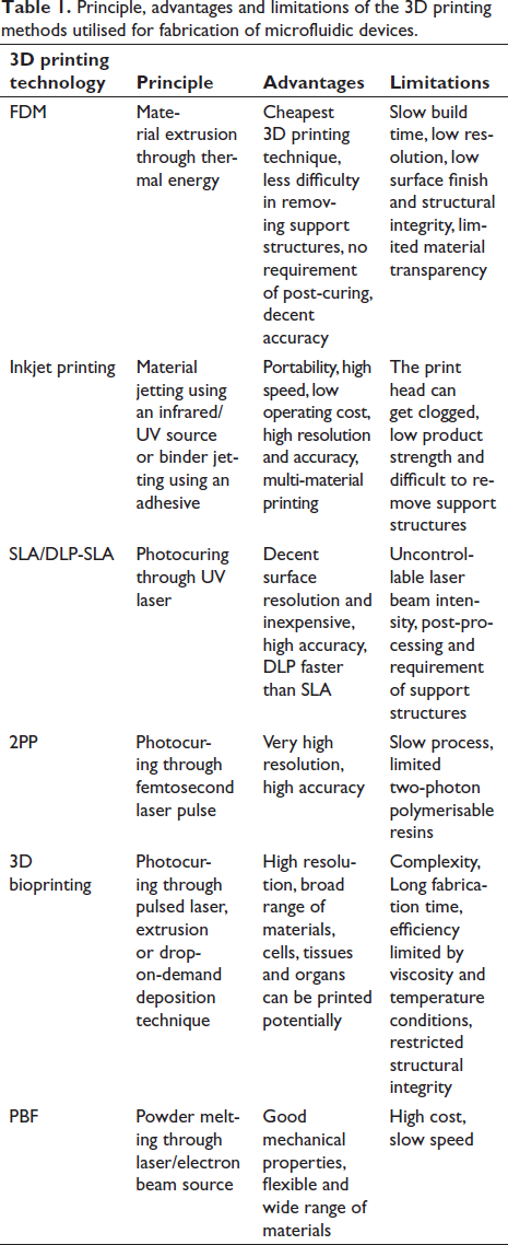
However, most of the currently used techniques are limited by high cost, large setup size and extended fabrication time.32, 33 Lithography is mostly specific to the microchannel design of single-layered 2.5D structures and often involves the use of toxic chemicals. Using lithographic techniques to create multistep microchannels necessitates the use of a costly and time-consuming masking process, which can be complicated to realise. This limits the utilisation of LIGA-based processes for the development of complex out-of-plane structures.34, 35 Further, when complex design is a necessity, such as building biomimetic structures that resemble their natural counterparts, existing manufacturing technologies, such as freeze-drying 36 and salt-leaching lack the flexibility to tweak the design locally. Therefore, a fabrication method is necessary which is faster, flexible, cost-effective and has low spatial requirements. Three-dimensional (3D) printing has evolved out as a potential solution which translates 3D designs into physical objects through additively layering suitable materials under a computer-controlled ecosystem. Hideo Kodama of the Nagoya Municipal Industrial Research Institute, Japan, first demonstrated the printing of a 3D object through UV-assisted photo-hardening of plastic material. However, Charles Hull from 3D Technique Corp. designed the first 3D printer in 1984 and later received the first patent for a stereolithography (SLA) printer (3D printer) in 1986, which is when 3D printing got its start. 4 Table 1 summarises the characteristics of the currently utilised 3D printing technologies in the fabrication of microfluidic devices for biological applications.
Principle, advantages and limitations of the 3D printing methods utilised for fabrication of microfluidic devices.
Fabrication of microfluidic devices through 3D printing
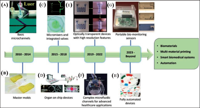
With advancements in technology and market competitiveness, 3D printing has turned out to be a simple, fast and cost-effective technology for fabricating bioanalytical microfluidic devices eliminating the intermediate steps of high-end lithography.37, 38 From initial applications in the fabrication of master moulds, 3D printing has evolved into a tool-in-demand for the development of almost fully automated functional microfluidic devices having miniaturised features (Figure 1). Extremely sustainable processes appropriate for industrial scale are made possible by the conjugation of additive manufacturing and microfluidics. 39 Some benefits of 3D printing for the microfluidics area include its simplicity, rapid and efficient prototyping without the need for photomasks, photoresists or cleanroom equipment. Users with minimum or no prior experience may easily recreate this process to build elaborate structures at micrometre scale precision. 40 3D printing involves a layer-wise deposition method working on a sliced CAD model which is fed to the desktop and integrated to a 3D printer. Powder bed sintering or selective interaction of photocurable resins or inks to a light source are often used for deposition. 41 Design modification of microdevices can be easily achieved by changing the design in a complimentary software. Recent developments in terms of speed, reliability and resolution have led to the consideration of 3D printing as an alternate method to conventional microfabrication methods such as micromachining, lithography and laser processing. 4 3D printers with several extrusion nozzles are used to create microfluidic devices made of various materials, allowing for the creation of fully integrated platforms with channels for fluidic movement, sample preparation, mixing and conductive surfaces for electrical measurements.
Devices fabricated using 3D printing include metal ion monitors, smartphone-based albumin testing systems, bacteria, protein detection systems, etc. 3D printing methods have been extensively used for manufacturing various mixers, pumps and valves at the micro scale 50 and fabrication of microfluidic devices such as gradient generators and flow-cells for analytical measurements,51, 52 microdroplet generators and components for modular microfluidics. 53 Microchannel fabrication with working speeds of 22 mm h−1 is being investigated by the microfluidic research community.54, 55 Buttner et al. 1 have demonstrated the fabrication of microfluidic devices in a few seconds using digital light processing (DLP)-SLA in a single exposure process. Printing methods and materials under consideration determine the structure of the channel printed or the durability of the model. In order to fabricate diaphragms for pneumatic actuation, stiffness is an important factor. The microfluidic system made of thermoplastic elastomers (TPE) has been found to be similar to the pneumatic PDMS microfluidic device in working mode but the calculated modulus is still eight-fold to that of PDMS. The versatile nature of 3D printing technology allows the use of various polymeric materials such as poly (vinyl alcohol), nylon, poly (ethylene terephthalate) (PET), poly (ether ether ketone) (PEEK), wood-polylactic acid (PLA) and TPE along with metals and biological entities.
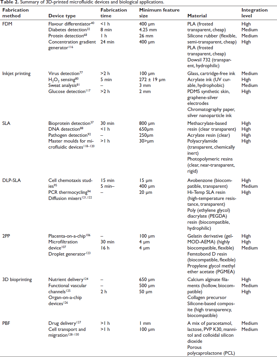
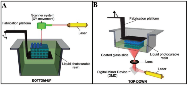
The resolution of today’s 3D printers is around 16-micron layer thickness which makes them suitable for microfluidics applications. Nonlinear optical micro-SLA is based on the multiphoton polymerisation of polymeric mixtures, enabling the production of 3D structures with submicrometric precision. Tanaka et al. 56 have reported a high resolution of 120 nm in defining 3D-printed structures. However, the full potential of 3D printing has not yet been completely exploited. 43 Most of the microfluidic devices realised through 3D-printing technologies have been fabricated through extrusion-based fused deposition modelling (FDM), SLA and inkjet printing methods. Commercial 3D printers range in price from a few hundred to thousands of dollars and can be used to print materials that cost tens to hundreds of dollars per unit mass or volume. Inkjet printing of photocurable materials is generally the most expensive category of 3D printing technologies. Inkjet printing offers an edge over digital microfluidics and paper microfluidics in terms of performance and production volume. Integrated microfluidic devices 57 have been inkjet-printed for application in transfusion medicine 58 and microelectronics for integrated circuitry. 59 FDM is typically the least expensive 3D printing technology available commercially. A heated nozzle is used to extrude fine filaments of semi-transparent thermoplastic materials. The FDM process allows for the use of low-cost thermoplastics such as PLA, PET, nylon, acrylonitrile butadiene styrene and conductive graphene filament based on PLA. 40 PEEK is also used owing to the unique mechanical properties and biocompatibility. 60 FDM has been used for the fabrication of prototypes of PDMS-based microfluidic devices, 61 direct printing of fluidic channel 62 sand fabrication of microfluidic mixers. 32 To ensure biocompatibility and transparency few researchers have also opted for direct printing of microchannels on a specifically chosen substrate through a special kind of 3D printer known as a direct ink writing printer which works similarly to the FDM process. 63 However, this technique is limited by the surface roughness and transparency of the fabricated devices. SLA-based printing requires a light source such as a laser (SLA) or digital micromirror device-based projector (DMD-PP) and photosensitive resin to fabricate objects. Acrylate-based clear plastic has been utilised to develop 3D-printed microfluidic devices 51 and fluidic devices that carry out efficient mixing through deformable diaphragms and unibody pneumatic valves. 55 Similar to inkjet printing technologies, printing devices having channels less than 250 µm size may be difficult in SLA-based printing and an additional post-processing step is necessary to maintain the structural integrity. While the majority of these devices based on DLP use top-down projection methods, bottom-up projection methods can give faster build-up time, improved resolution and reduced material wastage. 64 However, a major disadvantage is material interaction with the base plate which has been overcome by the use of a protective coating. 65 DMD-based projection printing has evolved as a high-throughput DLP technology with excellent biocompatibility for cell culture and encapsulation. The basic attempt of this article is to review the current state of development of the various types of 3D printing technologies towards the fabrication of microfluidic devices for biological applications. The following sections systematically present the major 3D printing technologies, with details of setups of the fabricated microfluidic devices and biological applications as available in the literature. The contribution of various 3D printing technologies in the development of microfluidic devices is summarised in Table 2.
Summary of 3D-printed microfluidic devices and biological applications.
3D printing technology and biological applications
Fused deposition modelling
Figure 2A represents the extrusion-based 3D printing setup developed by Yao et al. 32 A desktop 3D printer working in integration with a material extruder with a single syringe which is regulated by a stepper motor has been developed.
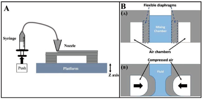
A CAD model is generated in an STL file which is transformed to a machine-readable G-code file with all the process parameters defined. The nozzle of the 3D printer follows a desired pattern as directed by the G-code to deposit the silicone material which can be cured without heating on a platform maintained at room temperature. FDM process accuracy has relied on the alignment of the coordinate axes, since belt tension, motor micro-stepping and threaded rod pitch are directly used to influence the system resolution at the micron scale. Material printing methods have affected the deposition rate, layer spreading, adhesion and thermal gradients, further affecting resolution and device performance. 66
Microfluidic devices fabricated through FDM technology
A diaphragm-driven micromixer has been designed by Yao et al. 32 to carry out active mixing of fluids. A schematic representation of the working principle of the FDM-printed micromixer is shown in Figure 2B. The device consists of one centrally located cuboidal fluid mixing chamber and two distinct air chambers. Figure 2B(a and b) demonstrates the side and top view of the diaphragm-driven micromixer. The air and fluid chambers are partitioned by two flexible diaphragms designed as the long internal walls of the micromixer chamber. The silicone rubber has been made to bond to the glass substrate firmly using the silicone rubber deposition technique. Compressed air has been used to deflect the flexible diaphragm and these deflections led to efficient mixing of the incoming fluids in the mixing chamber.
A similar device has been fabricated by Wang et al. 67 which involves a micropump actuated pneumatically and a micromixer integrated on a common platform. In another work, Kadimisetty et al. 68 developed a microfluidic device for protein detection (Figure 3). It consists of three pre-filled reagent chambers which are attached to a common microfluidic channel in a 40 × 30 mm base array.
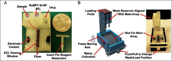
The flow of samples and reagents is regulated by a 3D-printed external insert in a horizontal position. Wash reservoirs with the capacity of ~1.6 mL buffer are used to wash off excess immunoreagent volume from the primary microfluidic array after the immunoassay. The sensor and reference electrodes have been screen-printed with carbon graphitic ink using a patterned adhesive-backed vinyl mask template. High output electrochemical double-layer supercapacitor has been used to power electrochemiluminescence (ECL), which is developed through the electrochemical oxidation of tri propylamine and RuBPY when a voltage of 1.5 V is applied on the sensors.
Biological applications
Yao et al. 32 proposed a solution to the inability of early detection of type-II diabetes using currently available diagnostic techniques by using a 3D-printed pneumatic microfluidic device (Figure 4A). Dow Corning 732 has been used as a material to print pneumatic micromixers on glass substrates in 8 minutes. IDEs are made by conventional MEMS methods. Compressed nitrogen is used to cause deflections of the diaphragm. This is followed by sample mixing in the mixing chamber. Insulin antigens are collected by the insulin antibody-coated magnetic beads. A permanent magnet located close to the IDEs holds the magnetic beads near to the electrodes for impedance measurements. The resultant spectrum is recorded by an impedance analyser (HP 4192A). The impedance has been found to decrease with increasing concentration of insulin from 10–10 to 10–5 mol L−1. Kadimisetty et al. 68 developed a novel, low cost, gravity-flow, 3D-printed, portable immuno-array for the detection of proteins with high sensitivity (Figure 4B). Capture antibodies (Ab1) have been applied to carbon sensors, followed by incubation and the addition of casein, while reagent chambers pre-filled with diluted serum samples in calf and detection antibodies flow through the main array and detection channel after removing the insert, and subsequent steps include buffer release, sample incubation and the flow of Ab2-RuBPY-SiNPs for detection.
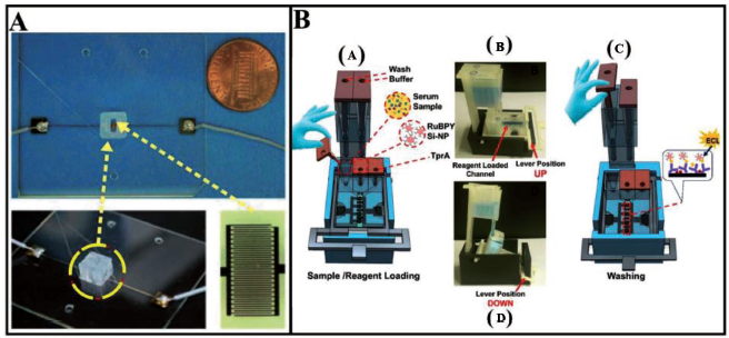
The capture of ECL through a CCD camera and estimation of light intensities has revealed accurate detection of three types of proteins with detection limits of 300 fg mL-1 for prostate-specific antigen (PSA), 420 fg mL-1 for platelet factor 4 (PF-4) and 535 fg mL-1 for PSMA ranging from 500 fg mL-1 to 10 ng mL-1. These results have fairly correlated to clinical ranges of these proteins in serum after sufficient dilutions indicating high selectivity. High accuracy and good correlation of ECL arrays with ELISA for cancer patient samples have indicated potential for next-generation clinical applications. However, it is worth to note that these devices lack complete integration in design. An Integrated microfluidic electronic device has been fabricated by Gaal et al.40 using a less expensive and easily accessible material (PLA) as a substitute to PDMS, easily integrating other materials while printing. Flexible interdigitated electrodes have been readily included as a proof-of-concept in a microfluidic e-tongue capable of differentiating fundamental flavours. Along with employing just microliters of the samples, this 3D-printed microfluidic tongue has been produced in less than an hour of time, which is difficult to do using typical PDMS processes. Romanov et al.66 have used their FDM-printed microfluidic device for DNA tracking and identification using DNA fusion analysis. On-chip DNA melting analysis has been done through their transparent, heat-resistant, 3D-printed microfluidic device. This experiment could distinguish between different DNA sequences by monitoring their distinct, temperature-dependent melting profiles as they transitioned from a double-stranded to a single-stranded state. Most of the FDM-printed devices offer poor resolution. The resolution of these printers is still limited to 250–300 microns for reproducible fabrication of open-microfluidic channels without a support structure. Lee et al. 69 have characterised 3D-printed microfluidic chips through tissue engineering-based microfluidic platforms and found that PolyJet printing offered better resolution in all axes than FDM. Circulating tumour cells (CTCs) isolation from blood has crucial prognostic and therapeutic implications for the treatment of cancer, however, due to lesser concentration of CTCs, the technique is difficult to implement. A high surface area microfluidic device with fluid flow control has been created using 3D printing technology and precisely designed inner components, boosting tumour cell capture efficiency by Chen et al. 70 The 3D-printed microfluidic approach, when combined with enzymatic lysis of the collected tumour cells and the examination of the released DNA in the blood, could allow for the isolation of rare tumour cells and early diagnosis of cancer metastasis. Using 3D-printed interconnected microchannel scaffolds, Felton et al. 71 have revealed an innovative, low cost, open-source approach for the fast prototyping of complicated microfluidic devices in PDMS. The FDM process has also been used for pathogenic bacterial detection.72–74 These single-extrusion scaffolds include interconnected ends that have been used to swiftly assemble complicated microfluidic systems before being immersed in PDMS to create an imprint of the microfluidic configuration. This simple yet novel technique has drastically lowered the barrier to microfluidics research and teaching, allowing for the quick development of POC lab-on-a-chip diagnostic equipment that is really cheap throughout the world.
Major challenges
More efforts are required towards optimisation of the design variables and development of complex 3D-printed microfluidics. The detection ability of these systems is still limited for low-concentration detection. Further integration is required in order to bring down the spatial requirements and improve portability. The 3D-printed micromixer can be combined with more micropumps and microvalves in order to further automate the assay to a lab-on-chip technology and bring down operator intervention and simplify the assay protocols. Surface roughness of the printed TPE is high as compared to moulded PDMS which can lead to trapping of sample particles. TPE NinjaFlex used in 3D-printed devices is semi-transparent affecting visibility and Young’s modulus which is higher than PDMS. The drawback of FDM is that air space and fusion lines are always persistent between each laid-down layer, and this can compromise the resolution of the final product.
Inkjet printing
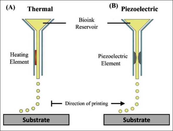
Inkjet printing operates on a ‘bottom-up’ approach, unlike the other traditional 3D printing methods as discussed earlier. An inkjet printer consists of an ink reservoir, where the ink is loaded, and a channel that links the ink chamber to the printing nozzles. The ink is jetted as droplets through the nozzle of the printhead with a volumetric range of nano-to pico-litre. 75
The structural design is developed in computer-aided design (CAD) software which is fed to an Inkjet printer. A desktop computer analyses the 2D or 3D design and actuates the base which holds the substrate, or the printhead which supports the jetting nozzle through electrical signals, where the ink is ejected from the printing nozzle and deposited on the substrate. Figure 5 demonstrates the inkjet printing setup with two popularly used actuation techniques.
Microfluidic devices fabricated through inkjet printing technology
A digital microfluidic device (Figure 6) has been inkjet printed by Dixon et al. 77 and applied in the fabrication of inexpensive, miniaturised diagnostic assays. The device consists of inkjet-printed and roll-coated flexible substrates which form the bottom plates containing arrays of 52 driving electrodes (2.8 mm × 2.8 mm).
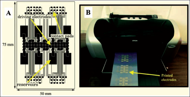
The setup includes 8 reservoir electrodes and 8 dispensing electrodes to dispense and deliver the test samples and contact pads. Inter-electrode spaces have been designed to have 100 µm spacing. The electrodes have been printed onto a roll of inkjet-printed material to create the substrate. Post printing, the 1 m roll is exposed to room temperature conditions overnight before being coated with a dielectric layer made of Cyanoresin CR-S cyanoethyl pullulan, followed by a hydrophobic coating made of an amorphous fluoropolymer. The device has been assembled by using double-sided adhesive tape to join the top and bottom plates. The device can process a unit droplet volume of 1.20 µL. Inkjet printing can be utilised to build digital microfluidic (DMF) circuits, making them less expensive than PCB-based designs and allowing for faster design iteration cycles 78 has demonstrated the fabrication of an inexpensive inkjet-printed digital microfluidic circuit without using a cleanroom. Hydrogen peroxide (H2O2) is the final product for many of chemical reactions and hence detection of H2O2 becomes necessary in bioanalytical chemistry. Further, hydrogen peroxide is also an important diagnostic entity in food, clinical and industrial analyses. 79 An all-inkjet-printed H2O2-sensor has been fabricated by Maejima et al. 80 for paper-based sensing of hydrogen peroxide. A step-by-step procedure of the printing process is shown in Figure 7. An EPSON PX-101 inkjet printer has been used to print all the microfluidic channels and sensing devices and it can handle at least 3 pL ink by volume.
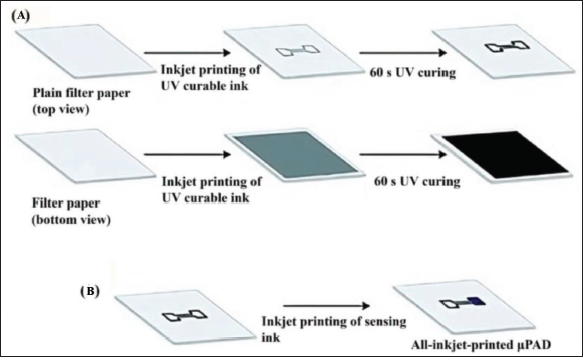
The inkjet printer is loaded with round-shaped filter paper affixed to A4 paper sheets with a circular cut-out section. The hydrophilic areas are masked through an aqueous solution of amaranth dye. The black ink is loaded into ink cartridges. On the upper side of the paper substrate, a pattern representing the hydrophobic barrier is printed. Post ejection out of the printer, the paper is exposed to UV light for 60 seconds in this work. The ink is UV-cured through continuous wavelength irradiation. The paper is then flipped over, and the process is repeated for the reverse side, with a uniform black shape fully opaque covering the full surface of the pattern printed on the topside. This work has demonstrated a fully integrated printing technology of paper-based microfluidic analytical devices.
Biological applications
Dixon et al. 77 have used their inexpensive inkjet-printed microfluidic device to carry out the detection of infectious rubella virus (RV) with excellent clinical sensitivity and specificity for RV IgG and IgM in a panel of serum samples (Figure 8A). The procedure involves dispensing and immobilisation of virus-coated paramagnetic particle droplets followed by dispensing and mixing of test samples with the paramagnetic particles for 5 minutes. The mixture is then treated with HRP conjugate solution, H2O2 and luminol-enhancer solutions followed by flow to the detection chamber wherein the chemiluminescence (CL) is detected and measured. The detection limit of 0.02 IU mL has been found to be substantially below the recommended limit of 10 IU mL for RV detection as reported in this work. The microfluidic device fabricated by Maejima et al. 80 is a truly integrated sensing device which has been successfully applied as an H2O2 detection system from enzymatic samples. The H2O2 sensing ink is loaded into the specific reservoirs and printed in 8 layers into the signal sensing region of a printed patterned paper substrate. 3 mL of the H2O2 sample in a citric acid–phosphate buffer (pH5) has been used. After loading the sample, the devices are scanned and the colour intensity in the sensing region is analysed. The limit of detection measured is 14.4 and 33.8 µm for covered and uncovered channels, respectively. It has been concluded that covering of channels leads to less volume of sample fluid reaching the detection area.
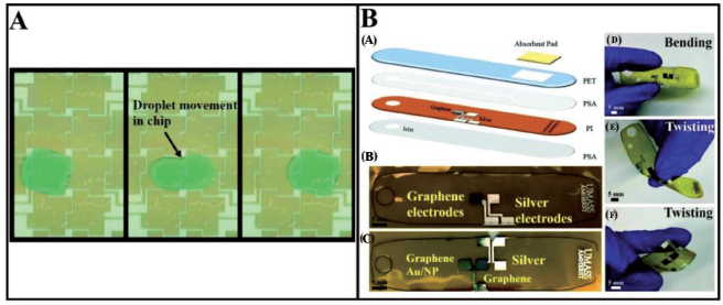
Recently, Naik et al. 81 have carried out the fabrication of a microfluidic device for sweat analysis. Electrochemical measurements have been made through biosensing materials in the form of graphene and silver electrodes and an adhesive-based microchannel. A synthetic skin is developed to simulate a sweat delivery system through eccrine pores on the human body and hence validate the potential of the inkjet-printed device towards real-time sweat detection when integrated to the human body. A detection limit of 10 pM has been achieved for both cortisol and glucose detection. Figure 8B shows the fabrication process of the microfluidic device. The device has opened a window of inkjet-printing methods for the fabrication of inexpensive, multiple-detection and flexible wearable devices for single-use and continuous biomarker measurements. In addition to continuous glucose measurements and single-use cortisol measurement, the inexpensive wearable inkjet-printed devices developed by Naik et al. 81 can also be used for real-time detection for other analytes and integrated with electrochemical systems with slight modifications. A similar work has been executed by Nyein et al. 82 and Matsusaki et al. 83 have developed 3D Human Tissue Chips through inkjet cell printing. A combination of single-cell printing and LbL printing of FN-G solutions has been used to effectively accomplish quick and automated hierarchical cell manipulation, resulting in the construction of 440 micro-arrays of human tissue constructions comprising of several cell types on a single chip. Distinct multi-layered structures have been clearly detected.
Major challenges
The devices prepared often have reported limited functionalities. Some researchers have been able to produce high-performance devices but those again involved expensive materials. The biggest limitation of most of the devices produced by inkjet printing has been the production of dielectric and hydrophobic coating layers through spin coating and other vapour deposition processes which necessitate a cleanroom-like environment which in turn limits scalability and production rate issues. Although Dixon et al. 77 could overcome these issues but scalability by using commercial inkjet printers still remains unaddressed. The radial flow of material due to solvent evaporation and a corresponding reduction of the solution quantity often leads to non-uniform deposition which is better known as a coffee-ring effect. Furthermore, nozzle clogging due to viscosity limitations of the ink material 84 also restricts the free expansion of Inkjet printing technologies towards microfluidic device fabrications.
Stereolithography
SLA is a 3D printing method that uses a laser or DLP source to cure molten polymer material (Figure 9). SLA is a little more expensive than FDM but it is superior to FDM in terms of surface finish, resolving capacity (up to 300 µm) and ability to fabricate highly transparent devices using acrylate-based resin.
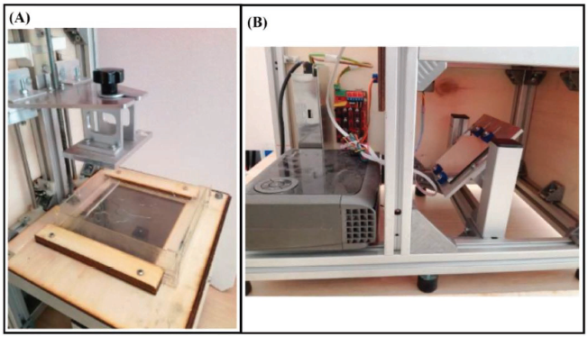
Tang et al. 37 have used a desktop 3D SLA printer, Form-lab Form 1+ and clear transparent methacrylate-based resin to fabricate an automated microfluidic device. It is worthy to note that the Form-lab Form 1+ desktop SLA printer is capable of printing layers down to 25 µm thickness with a minimal feature size as low as 300 µm. 86 The CAD model for this design is developed using the software 123D design and converted to an STL format. The CAD model is then transferred to the Form-lab software, Pre-Form, where optimisation of the printing process is carried out. A UV laser source is used to scan the desired region to cure the fluid resin material. The high-intensity laser then is used to harden the cured resin material. The build surface moves down along the z-direction by a dimension equivalent to the thickness of a single layer. A recoating blade sweeps over the build platform to apply a new layer of resin. This process goes on until the build is completed. The SLA printer can yield a good resolution of fabricated products at a relatively low cost due to minimal utilisation of the liquid medium. In addition, the design of the SLA printer is focused to be portable, faster and inexpensive to make it ideal for personal use.
Microfluidic devices fabricated through SLA technology
Tang et al.
37
have fabricated a 3D-printed fluidic device which consists of three reagent reservoirs with a volume of 125 ± 5 µL, separated by empty reservoirs to prevent the mixing of the reagents. Figure 10A shows the schematic representation of a printed microfluidic device used for protein detection in their work. A 3D mixer network of around 100 turns and a volume of 210 ± 10 µL has been printed ahead of the reservoirs. This is followed by a 30 ± 2 µL detection chamber in the device design. The detection chamber is characterised by a PDMS base and consists of a poly-
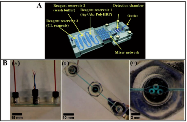
Bishop et al. 41 have also developed microfluidic devices through a Form 1+ 3D printer and transparent methacrylate resin (Figure 10B). Currently available in the market, threaded fittings are multiplexed with PEEK tubing and ferrules and put into SLA-printed ports to facilitate flow into the microfluidic channels. ‘Ag’ wires of 0.5 mm diameter and pencil graphite rods have been used to make the disc electrodes. The graphite electrodes are wrapped up and put into threaded fitting’s opening. Adsorption by layer-wise deposition of polycation PDDA and DNA in 0.5 microlitre volume on the pencil graphite electrode is used to create multilayer DNA-coated graphite electrodes. A bipotentiostat is used to conduct electrochemical tests.
Biological applications
Tang et al. 37 have used a valve-free automated microfluidic device to generate an integrated unibody immunoassay to detect protein biomarkers (Figure 11) for early cancer detection. As shown in Figures 10A and 11A, reservoir 1 has been filled with a mixture of detection antibodies and diluted poly-HRP, reservoir 2 has been filled with a wash buffer and reservoir 3 is pumped with a mixture of the chemiluminescent reagent. Then, a mixture of protein in 500-fold diluted calf serum and human patient serum is loaded into reservoir 1 and made to flow to the 3D mixing chamber thereby triggering a reaction between the immuno-reagents and corresponding protein partner. 3D passive mixing has ensured cost-cutting and better mixing performance. A programmed syringe pump is incorporated to regulate the flow of the mixture into the immobilised capture antibodies in the detection chamber. CL measurements have been carried out using a G: Box bioimaging system equipped with a CCD camera and GeneSnap software.
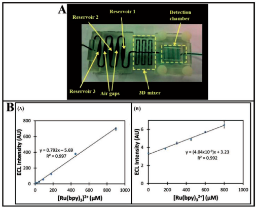
A detection limit of 0.5 pg mL−1 has been reported for prostate cancer biomarker proteins PF-4 and PSA in diluted calf serum. Results have been fairly validated through comparison with results on human patient serum samples with ELISA which indicated high selectivity and specificity of the 3D-printed device towards detection of two proteins out of many in human serum. This protein detection immuno-device has been developed in an unibody fashion for early cancer detection in a total assay time of 30 minutes. The device developed in the work is reported to be a fast and reliable immuno-array for cancer detection at a low cost, although sensitivity and detection limits reported are inferior to some earlier fabricated devices. 87 A similar fabrication method has been used by Bishop et al. 41 for the development of a fluidic device through SLA using transparent plastic electrodes assembled to a closed 3D-printed fluidic channel which can be utilised to monitor analytical electroluminescent (ECL) output. The electrodes have been included into an array with closed transparent channels to aid the flow process. This made it possible to observe the electrodes in the channel for ECL readings which are easily monitored by using a CCD bioimaging camera. A 3-cc syringe linked to the fluidic device inlet port is used to administer the reaction mixture to the electrode surface. The closed clear devices used in this architecture feature embedded pencil graphite working electrodes with Ag/AgCl reference electrodes to measure ECL signals from solutions having [Ru(bpy)3]2+ in 0.2 M phosphate buffer with 100 mM tri-n-propylamine (TPA). The measured ECL intensity increases proportionally with the concentration of [Ru(bpy)3]2+ in solution (Figure 11B). Guanine bases in DNA strands work as co-reactants for [Ru(bpy)3’s] electrochemiluminescence emission. ECL responses from DNA-coated pencil graphite electrodes, on the other hand, have been significantly lower than those monitored using 100 mM TPA as the co-reactant. These clear resin chips allow for the sensing of ECL at low levels, facilitating the path for the development of microfluidic biosensors and arrays. For a 10-second exposure period, the detection limit has been found as 7 M. The resin for the SLA-printed fluidic devices has been estimated to around cost $2.50, and printing has been observed to take 3.5 hours with a 50 µm resolution. In the same direction, Kadimisetty et al. 88 have used a 3D-printed microfluidic array (10 nm deep microwells) to detect damaged DNA from chemical metabolites in environmental samples. Liquid samples are injected into the array, where they are digested through the use of human enzymes and products react with DNA if feasible, and DNA damage is detected using ECL and a camera. Such POC diagnostic devices can also be used to detect various proteins using the ECL technique. The automated immunoassay has been shown to be useful by identifying an eight-protein prostate cancer biomarker panel in human blood samples in 25 minutes. 89 The results indicate a great hold of promise for SLA-based 3D printing technology towards the fabrication of complex and inexpensive microfluidic sensing devices. A microfluidic sensing electrode has been fabricated using the 3D printing SLA method which can monitor clozapine in blood samples at low concentrations with an acceptable detection limit and sensitivity. 90 However, most of these SLA or FDM printing methods are limited by printing of a single type of material. This restricts the functionality of the methods to wider applications without assembly and proper bonding. Ruiz et al. 91 have produced hybrid structures consisting of a hard SLA-printed component made of clear polymethacrylate-based resin and an FDM-printed soft, flexible component made of thermoplastic polyurethane elastomer. The soft material deposition is preceded by heating of the base plate on which the hard part is mounted through the adhesive. This is done to confirm the proper adhesion of the extruded TPU material to the rigid material. Three distinct devices have been developed to demonstrate the potential applications of these hybrid structures namely, a finger-powered micropump which can hold 2,000 µL of fluid per minute, sufficient for biomedical applications, a microfluidic quick connecter which can serve as a leakage-free liquid transportation device and a bacterial (Salmonella Typhi) DNA amplification assay. A similar device has been developed by Lee et al. 92 for the detection of pathogenic bacteria using SLA-printed microchannels and magnetic nanoparticles. Escherichia coli (EC) bacteria are captured in milk using antibody-functionalised magnetic nanoparticles. A light absorption spectrometer has been used to evaluate the quantity of EC bacteria, and the limit of detection has been found to be 10 cfu mL−1 in buffer solution and 100 cfu mL−1 in milk. A novel immunomagnetic flow assay on a chip has been developed in an earlier work by Lee et al. 57
Major challenges
The detection ability of the systems has been found to be limited. More efforts are required towards optimisation of the design and fabrication of the 3D-printed microfluidic device. Better sensitivity and detection limits have been offered by competing methods. Also, micropumps can be integrated to the chips to bring down the spatial requirements and achieve further automation. Further automation is highly required to bring down operator errors and simplify assay protocols.
Digital light processing-SLA
Projection SLA (DLP-SLA) is a 3D printing method that uses a DLP source to cure molten polymer material (Figure 12). In DLP-SLA, microfluidic channels are designed in CAD software and saved in STL format. 1 Slicing into 2D cross-sections is done in an open-source package. One slice is sufficient to transfer the pattern and complete the final microfluidic chip. The focus of the high-resolution DLP system is the most critical aspect. DLP lens controls the intensity of projected light and hence the exposure time. Lens alignment and focus can be adjusted by calibration property in the processing software. Higher resolution and smaller structures can be obtained by incorporating an external convex lens between the DLP lens and the microfluidic chip. However, improvement in resolution is accompanied by increasing light intensity. Beyond an optimal value, this can lead to overexposure of certain areas on the chip. The minimum area is cured for a particular optimal focal length.
A DMD in an example of a DLP chip. The micro-mirrors project patterns constructed with pixels for a total resolution of 1,920 × 1,080 pixels and cure the resin through projected light. After exposure, curing and cleaning, the input and output tubing are attached to realise the chip. The DLP-SLA system fabricated by Tzivelekis et al. 94 has used 405 nm (27.5 mJ cm−2) UV light to project high-definition patterns with a 50 µm resolution on a maximum construction area of 64 × 40 mm. The chips and channels have been printed through Formlabs Hi-Temp SLA resin because of its resistance at high temperatures and transparent nature. The printed parts can withstand temperatures up to 289°C with the least deformation after UV curing for 1 hr and isopropyl alcohol washing.
Microfluidic devices fabricated through DLP-SLA technology
High-resolution (10–15 µm) features have been developed by DLP-SLA technology for biomedical applications such as micropillars, valves, pumps and microchannels. Utilising the absorption range of the biocompatible resin Avobenzone, Boaks et al. 95 demonstrated cellular migration through their lab-on-chip device (Figure 13A). Enclosed serpentine microchannels have been fabricated through DLP-SLA by Tzivelekis et al. 94 to carry out two-step polymerase chain reaction (PCR) thermocycling. Figure 13B demonstrates the DLP-SLA-printed microfluidic chip and two-step PCR thermocycling set-up. Sacrificial wax is used to fabricate sophisticated channel patterns, infeasible at a single step. The microfluidic geometry had been made in a manner that it consisted of an open microchannel (400 × 700 µm) designed in a serpentine-like pattern over two distinctive regions covering a 51 × 38 mm area.
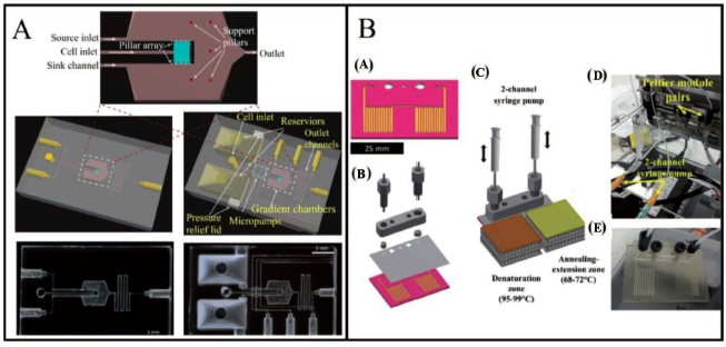
Flow is controlled by a cap with 500 µm inlets. The thermocycling step is further defined by the time of residence of the sample fluid on specially designed temperature regions supported through Peltier elements. The fluid exchanges heat with the Peltier pairs on a chip during the flow process. The ‘wet’ channel area is approximately 349 mm2 with a capacity of 50 µL reaction fluid containment. Enclosed drilling or laser ablation can be used to make inlet and outlet holes 1 as shown in Figure 14.
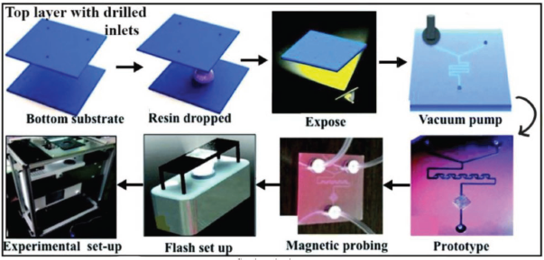
In their device, the resin is sandwiched between two 25 mm × 25 mm PMMA sheets or glass slides with drilled inlets and outlets. The pattern is projected onto the top surface of the glass and the device is exposed. The unbonded resin is removed using a vacuum application after the exposure step. The height of the chip is governed by the thickness of the resin material sandwiched between two surface plates, one being transparent.
Biological applications
Tzivelekis et al. 94 have further developed a monolithic microfluidic chip geometry using a two-stage DLP-SLA printing method to carry out PCR thermocycling (Figure 15A). A 50 µL sample (20% v/v glycerol in purified water) is filled into a chip through a mechanical pipette and placed in the denaturation chamber. The chip is connected to the two-channel plastic syringe (1 mL) pump and polypropylene tubing from both ends. Each serpentine channel region of the chip is then subjected to heating between the Peltier elements. The fluid sample is oscillated front and back over the Peltier region to complete the thermocycling process. Plastic syringes are used to pressurise the chips to eliminate leakages. With an 80:20 water: glycerol mixture, a full two-step PCR protocol is run at the specified temperatures for denaturation, annealing and extension steps, extending over a total time of 9.75 minutes. Post-processing of printed chips under UV light and solvent cleaning has been able to reduce PCR-inhibiting residuals. PCR inhibition is one of the major challenges in operating through microfluidic devices. The problem gets intensified when a photosensitive resin is used for the fabrication of miniaturised structures. 96 Coatings like spin-on-glass, 97 albumin, 98 etc. have been used by people to prevent PCR inhibition. Furthermore, channel surfaces dip-coated with polyethylene glycol and a silane static coating have been found to decrease the leaching interface hereby, reducing polymer interaction with enzymes and improving device efficiency for DNA amplification through PCR.
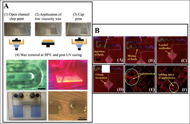
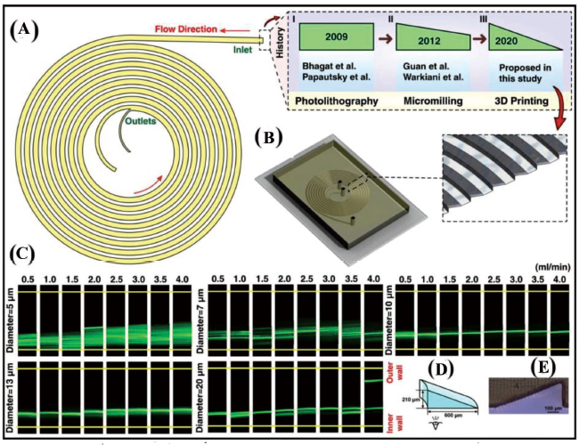
High surface-to-volume ratio chips coated with hydrophobic silane and polyethylene glycol have been observed to show slightly improved enzyme activity by limiting the leaching interface and bimolecular adsorption on the chip. Buttner et al. 1 have developed microfluidic devices such as spiral mixers, fractal gradient generators and 3D micromixers through the projection DLP-SLA printing method which can be utilised for agglutination assays for POC applications (Figure 15B). A Y-junction and 2D microfluidic mixer have been united into a microstructural region to hold cells or proteins (antigens or antibodies) known as agglutination. These microstructural zones (100 µm in size) have been fabricated using DLP-SLA methods also known as the flash microfluidic method. The antibodies are initially loaded onto latex support followed by reaction and precipitation with an antigen to exhibit an agglutination process. Agglutinates are captured at the V-shaped structures encircled in blue in Figure 15B. This fabrication technology may be useful in the analysis of single-cell or drug-delivery systems. Compared to other commercially available 3D printing methods, this has proved to be a fast fabrication method and has been utilised for the development of different types of micromixers, gradient generators and 3D capture zones for agglutination assays. Furthermore, this technique has been used to fabricate solid channels by image inversion and mould-making for PDMS casting. Razavi Bazaz et al. 99 have proposed a DLP-SLA fabrication technique as a solution to current limitations in terms of microchannel geometry (rectangular or trapezoidal) being developed by conventional lithography techniques (Figure 16). Traditional microfabrication techniques have limitations such as difficulty in producing sharp corners or generating spiral loops in the vicinity to each other. A right-triangular cross-sectioned (600 × 210 µm) spiral inertial microfluidic channel has been developed within 2 hours, that can be used for DU145 cell separation for various Reynold numbers in biological assays. A double-coated pressure-sensitive adhesive tape has been used to seal the open channels and transparent top surfaces. The cultured cells post-separation have shown a resemblance to standard morphology. Flow cyclometry has revealed preserved viability among the cells. The real-time PCR analysis has revealed similar gene expressions for treated and untreated cells, indicating that cell metabolism and progression is not significantly affected during their processing in microchannels. The device demonstrated has been versatile, robust and exhibiting good stability in cell separation processes. Large microfluidic devices are desirable as they can handle high volumes of samples in a few hours so that bacterial cells can be preconcentrated in those large-volume samples. Park et al. 100 have created a 3D reusable microfluidic magnetic pre-concentrator (FMP), which is a plastic-based unibody device that can withstand severe temperatures and pH levels. Their findings have shown that employing 3D FMP to successfully preconcentrate EC cells originally in large-volume samples into smaller volumes at the sub-millilitre scale has increased the detection limit of an ATP luminometer.
Transparency is an important parameter when it comes to the fabrication of biomedical assays. Transparent channels for flow reactors have been first investigated by Barone et al. 93 The goal of developing a bespoke 3D printer based on DLP-SLA technology has gained flexibility and overcome the usual limits imposed by regular commercial systems. The potential of DLP-SLA technology for the manufacture of micro-fluidic chip models suits well for PCR applications, which is a critical technique in biomolecular diagnostics for amplification of sequences of nucleic acid and has been studied by Tzivelekis et al. 101 The printed devices have been tested using an infrared (IR) mediated PCR thermocycler. Amplification of 75 base pair target.
DNA sequences using fluoro silane and glass-treated chips have produced amplimers commensurate with control reactions, but non-silanised chips yielded weak or no amplimers. It has been found from test results that the IR thermocycler has functioned and that the printed and silanised SLA polymer has been established to be PCR-compatible. Slip-Chips are two-part microfluidic systems that may be adjusted to modify fluidic routes for a variety of tasks such as the simulation of tissues. At this moment, the manufacture of these prototype devices necessitates the use of a competent microfluidic specialist, such as wet etching or alignment processes. In most circumstances, Slip-Chip functioning necessitates an optically transparent, smooth, planar, fluorophilic and hydrophobic surface. Catterton et al. 102 investigated DLP technology, which is fast, repeatable and readily shareable, as a method for prototyping Slip-Chips. The device has been made up of two-layered components: a sealed channel with an outlet valve and a tissue slice cultivation chamber having perusable support. After optimising the device design, the group has showed its functionality by locally loading a chemical probe to hydrogel slices and living tissue having 120 µm resolution. 102 Beckwith et al. 103 have described the creation of a completely 3D-printed microfluidic device that offered a dynamic system for permeating and maintaining tumour regions from a biopsy sample. The detailed, non-cytotoxic and see-through tumour capture includes channels for quick, leakage-free fluid interconnects, an in-line capture for eliminating bubbles generated by oxygenated fluid sample flow or tumour perfusing procedures, and an array of microchannels for supplying samples (immune cells) to the captured tumour entity. A multi-day capturing experiment has demonstrated the ability of the device to maintain a live tumour entity under dynamic suffusion—a system capable of modelling interactions of tumours with different medicine treatments in the existence of immune cells. 103
Major challenges
When adhesive sheets are used, multi-step processing becomes necessary due to material inconsistency in the microchannels. 1 Further optimisation and testing for durability on integrating different types of textures and standard electronic IC platforms are needed.
Two-photon polymerisation (2PP)
The 2PP process is similar to SLA in the fundamental working principle in that a chemical reaction leads to the photocuring of a resin material, triggered by a light source which results in the polymerisation of the resin. However, 2PP is a high-resolution 3D printing technology which can be utilised to achieve sub-micro-meter spatial resolution. Unlike SLA where single photon polymerisation is used to cure resin material near the surface, 2PP is characterised by simultaneous two-photon absorption, resulting in direct writing of complete 3D structure into photosensitive material with spatial resolution of less than 100 nm. 104 Due to the great resolution of the 2PP process, structural factors like exterior shape, pore size and interior porosity of manufactured objects may be accurately realised. Most of the materials used are transparent in the near-IR and have high absorption capacity in the UV spectral range. The threshold behaviour and nonlinear property of the 2PP process lets the achievement of feature resolution outside the diffraction limit of the photonics used by optimising the pulse frequency and energy. 2PP also reduces the need of cleanroom environment and eliminates the need for layer-wise deposition of traditional additive manufacturing techniques.
Microfluidic devices fabricated through 2PP technology
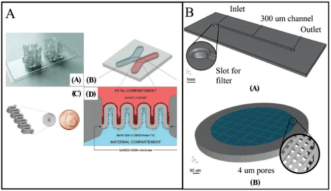
Complex structures have been fabricated successfully by using the 2PP method. Microchannels with varying cross-sections and heights can be easily coupled in a single device. 105 Mandt et al. 106 have used a customised microfluidic chip geometry to match the complicated structure of the placental barrier and the necessity of two central individually perusable channels. The microfluidic chip has two neighbouring chambers with a rectangular footprint of 76 × 26 mm. At the outermost points of each chamber, there are four inlets and outlets (Figure 17A(a)). The X-shaped chambers have a 1.4 × 1.0 mm intersection area, resulting in an adequate structure area (Figure 17A(b)). Poly-dimethacrylate with a molecular weight of 700 has been employed for chip production. Perrucci et al. 107 have developed a suspended micro filter created using a 2PP technique and successfully integrated into a 3D-printed microfluidic framework. It consists of two main components: a microfluidic channel (Figure 17B(a)), fabricated by SL, and a 4 µm porous filter (Figure 17B(b)) integrated to the channel entry through the 2PP method. The suspended micro-filter has been created using a 2PP Micro-3D Structuring System with a Femtobond D resin drop, which is made using a regular SLA system and an inexpensive resin. The microfluidic filtering system comprises of a single channel with a single inlet and outlet, as shown in Figure 17B(a). In another application of the SLA technique, a 3D printer equipped with a laser source of 405 nm, installed on a Galvo scanner has been used to create the single-channel chip. The microfilter structure is created with two major elements, as shown in Figure 17B(b): a solid circular outward ring and a grid filter structure. The novel printing strategy combining SLA-2PP technology has enabled the development of a multi-layered horizontal sieve structure with 4 µm pores inside a previously 3D-printed microchannel which is unlike most of the earlier single-layered filtration devices.
Biological applications
Although 2PP is a relatively new technology, its application window is expanding to the fabrication of micromechanical devices, microfluidic systems, biological devices and scaffolds for tissue engineering.108, 109 There have been multiple insights into the applicability of 2PP 3D printing technology towards the fabrication of stimulus-sensitive micro/nanodevices for biological applications. 110 Mandt et al. 106 have fabricated a customised microfluidic system with two culture chambers to create a placental barrier. They have used a specially designed 2PP device with a pulsed laser of 70 fs and a frequency of 80 MHz at 800 nm to create 3D structures within the sterile microfluidic chip. Two unique cell kinds can be cultured under different conditions using the four ports. The membrane utilised in this investigation is a simpler version of the placental barrier’s villous form, consisting of five loops in succession. The chip has been used to build a membrane with a wall thickness of 100 µm as shown in Figure 17A(c). The membrane of the placental barrier is covered with fibronectin. The membrane walls are injected with two distinct cell types, one for each side, in a sequential order. To simulate the foetal and maternal compartments, human umbilical vein endothelial cells (HUVECs) and BeWo B30 cells have been employed. Collagen biopolymers resembling an extracellular matrix are used in place of inorganic resins. The compliance of the micro-fabricated device with microfluidic pumps allows for steady flow and thus mimicked the flow of body fluid in vivo. The effect on foetal nutrition can be investigated by employing glucose analysers to measure the glucose level in the collected precipitate. In addition, the microfluidic device has provided the platform to comprehensively analyse the effect of arterial.
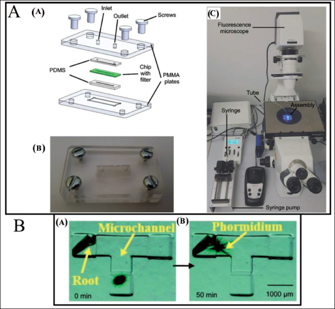
Hypertension on glucose transport by regulating the rate of pumping. The potential of 2PP technology in the production of high-resolution microfiltration systems has been presented by Perrucci et al. 107 The microfluidic chip is created using cleanroom technology, and the 2PP is employed to create the microfilter inside the channels (Figure 18A). Sorting tests are performed using fluorescence microparticles in real time to validate the applicability of the developed microfiltration device. Rather than sorting, 2PP features within an existing device are primarily utilised for the research of cell movement and motility. A special enclosure is created to seal the channels on the bottom and top, enabling for the controlled flow of liquid, because microfluidic chips have open channels. PDMS has been chosen as the sealant material because it is non-toxic (hence suitable for biological applications). Two PMMA plates are incorporated to clamp and maintain the PDMS sealings with the microfluidic chip within place, as shown in Figure 18A(a). The final assembly with the microfluidic chip inside is shown in Figure 18A(b). The created microfluidic filtration system is meant to be employed on a wide variety of cell sorting and filtration applications, such as blood cells. This work can be used as a base for the development of complex filtering systems that can be tested with real biological material, with the goal of eventually developing a multi-separation device that can function with micrometre-sized cells to nanovesicles. During the fabrication of microdevices in silicone elastomer by direct laser writing with femtosecond pulsed laser, Rekštytė et al. 112 have achieved 3D structuring with a resolution of 5 µm and a fabrication rate of 720 µm3 s−1, which exceeded previously reported figures by 300 times. Microfluidic devices have been fabricated by direct femtosecond laser writing for dynamic observation of microorganisms. Microchips known as ‘nonaquarium’ developed using direct laser writing, followed by annealing and wet etching, are capable of developing different microfluidic elements on photostructurable glass. These devices are used for the observation of microorganisms such as Euglena 113 and the mobility of Phormidium. 111 Investigation of the gliding pattern of Phormidium (Figure 18B), cyanobacteria, has helped in understanding the connections with seedling roots which help in the growth of vegetable seedlings. The use of laser-written microchannels has assisted in the reduction of gliding time (by reducing the distance between Phormidium and seedling roots) and using water as a medium which has a low viscosity. This has also brought down the evaporation of water as opposed to the case when microorganisms are cultivated on a petri dish. Furthermore, the effect of illumination wavelength on the gliding mechanism has also been studied. These integrated photonics microfluidic devices offer high functionality and keen analysis of dynamic aquatic microorganisms which can be utilised in high-grade biochemical analysis and medical sciences. Further, 2PP microfabrication and a subsequent PDMS micro moulding procedure have also been used to fabricate and study microdevices for transdermal delivery of insulin and other protein-based pharmacologic agents for the treatment of diabetes mellitus. 114 Hence, it can be concluded that the 2PP technique can be a potential 3D printing technology towards the creation of a variety of different micropumps with hydrogel materials that are controlled by PH, temperature and glucose concentration. 115
Major challenges
2PP offers a slower scan speed as compared to SLA due to the involvement of the tracing method. Also, a cleanroom environment becomes a necessity in most of cases which further raises the cost and limits the scalability and production level. The prospect of heat cure to undesired parts during the multiphoton polymerisation process may never be completely ruled out.
Further, precise laser pulse control is required to ensure extended investigations of component resolution.
Bioprinting
Current 3D printing methods may face challenges in biological structure preparation due to complex 2D and 3D microscale multi-layered structures, cell types, extra-cellular matrices and other entities in living organisms. 3D bioprinting is an advanced technology, which utilises Cells and biomaterials as printing materials. The main steps of 3D bioprinting are data acquisition, computer-aided designing of the 3D model (CAD), bioink preparation and biostructure printing. 131 Bioprinters now on the market feature distinct heads for printing diverse materials, hereby offering a significant advantage in creating multi-material cell environments. Dispensing and jetting printing heads are the two types of printing heads. Extrusion is a type of dispensing that involves the discharge of material, usually in the form of a filament. Hydrogels with a high viscosity are commonly used materials. The release of material as droplets for increased precision is referred to as jetting. It makes use of either an inkjet head or a microvalve. There are two types of techniques in this category: Continuous inkjet and Drop-on-demand inkjet. The creation of droplets is triggered by a volumetric change in the chamber, which can be thermal or piezoelectric.
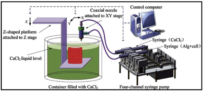
Figure 19 demonstrates a coaxial 3D bioprinting system developed by Gao et al. 124 The experimental setup includes motorised XY stages with a coaxial nozzle, a motorised Z stage with a Z-shape substrate where features are printed, a calcium chloride solution tank, a 4-channel syringe pump and a desktop computer that instructs the 3D motion stages and the pump. A high-pressure 4-channel syringe pump is utilised to discharge sodium alginate and calcium chloride solution at various fluid discharge rates. For planar feature printing, the XY stages are accurately administered to determine the nozzle placement. The Z stage is configured to maintain the speed of printing for individual layers to ensure successive fusing and gelation. The coaxial nozzle is used in the bioprinting system to fabricate hollow alginate filaments as shown in Figure 19.
Microfluidic devices fabricated through bioprinting technology
High-strength cell-laden hydrogel 3D structures with integrated microchannels have been fabricated through 3D bioprinting to carry out the nutrient delivery process. 124 Layer-by-layer production of cell-laden hydrogel structures has been achieved using a 3D bioprinting system with a Z-shape substrate. Variations in filament extrusion speed or platform motion speed might result in curved, straight, stretched or broken filaments. First, the sodium alginate and calcium chloride solution concentration and flow rate are regulated during the crosslinking procedure to obtain semi-crosslinked filaments. Following that, neighbouring hollow filament deposition in the specific area for fusion is controlled using motorised XY stages with the attached nozzle. The Z stage, which is affixed to a Z-shape platform, then slides down successively to print structure layers. The top two layers are fused always while keeping the lower layers under solidification. Figure 20A shows the fabricated 3D features with integrated microchannels. For the purpose of fabrication of vascular channels with thick collagen support, Lee et al. 125 have used 3D bioprinting technology. For the Luer connection to the media perfusion system, needle holes are punched in the central area of the flow chamber. The bottom and centre components are assembled prior to printing to provide a reservoir for the printed features.
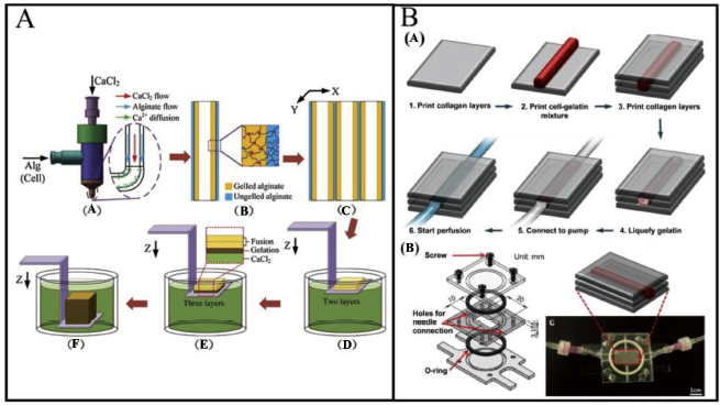
The top half is assembled when the printing procedures are completed, and the flow chamber is attached to the perfusion system, a digitally controlled peristaltic pump, a reservoir of cultivation medium and a customised flow chamber. Silicon tubing and polypropylene fittings link each component to the flow chamber. Using collagen precursor, gelatin and HUVECs, a vascular channel within a 3D collagen matrix is constructed using a layer-by-layer technique (Figure 20B(a)). A flow chamber is used to print the collagen precursor, which is then polymerised using NaHCO3 nebulisation (Figure 20B(c)). To complete the collagen gelation and, conversely, to solubilise the gelatin, the flow chamber is enclosed and maintained at 37°C for 30–40 minutes (Figure 20B(a), step 4). During the incubation procedure, the HUVECs in the gelatin slowly sink down and get connected to the channel’s inner surface. Every 10–15 minutes, the flow container is switched over to enable cells to attach to both the bottom and top sides of the channel. The flow chamber is then attached to a dispensing pump, and a mild medium flow is utilised to wash away the gelatin and create a perfused vascular channel (Figure 20B(a), steps 5–6).
Biological applications
The most exciting feature of 3D bioprinting is the provision to supply biocompatible polymers, phase-changing hydrogels without harsh chemicals, and various cell types concurrently and precisely to manufacture complex 3D biological constructions. One of the most appealing features of this printing process is its capacity to deposit live cells, growth regulators, and biomaterial scaffolds all at the same time, at specifically programmed areas to resemble the actual tissue organisation and that also using a dispensing method that is harmless for the cells. 125 Again, microfluidic devices are utilised in high-throughput screening applications such as drug screening, in vitro toxicity assays and functional genomic investigations. However, it is still challenging to replicate a sophisticated cellular structure. 86
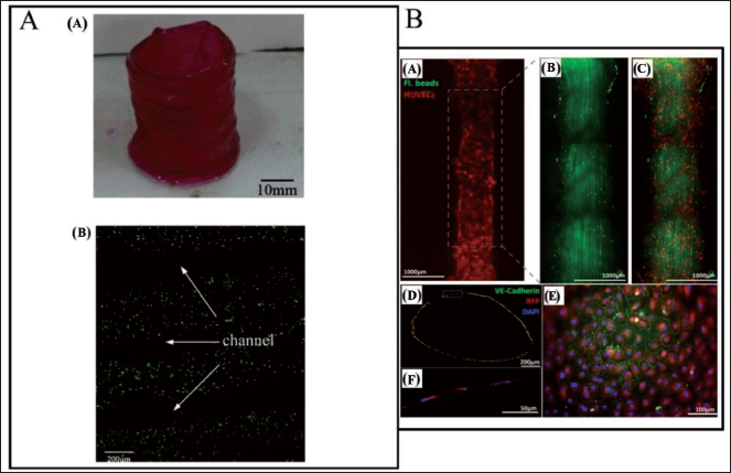
The utilisation of bioprinting as a remedy could be a viable option where cells and biomaterials are put in a precise spatial configuration. Efforts have been made to construct functioning live tissues and artificial organs with complicated structures using a mix of 3D bioprinting and microfluidics. 131 The bioprinter can create customised 3D-printed scaffolds for tissue regeneration or even pattern living materials like DNA and cells. Gao et al. 124 have demonstrated the viability of the bioprinted hollow alginate filaments with microchannels through encapsulation with L929 mouse fibroblasts (Figure 21A). Calcein AM is sustained within live cells and produces a strong uniform green fluorescence, but ethidium homodimer enters cells with damaged membranes and suffers a 40-fold increase in fluorescence upon adherence to nucleic acids, resulting in a vivid red fluorescence in dead cells. Cell viability enhancement has been seen indicating the importance of the bioprinted microchannels in the process. A similar work has been executed by Lee et al., 125 where they developed an in vitro fluidic vascular channel with perfused open lumen utilising only cells and biological matrices (Figure 21B). The total lumen surface is covered with endothelial cells to offer barrier function for plasma protein and dextran molecule. Under physiological perfusion conditions, the vascular channel has been capable of enhancing the viability (up to 90%) of tissue with a density of 5 million cells mL−1. Gene expression analysis has also been done to support the potential of the fabricated device in vascular biology.
As an in-vitro substitute for blood vessels, a fully functional hydrogel microchannel has been bioprinted by Bertassoni et al. 132 Cell culture is performed inside the microchannel to ensure that it is biocompatible. At the conclusion of each day, the cell viability is measured and found to be more within the channel as compared to the regular hydrogel blocks, demonstrating the capacity of a printed microchip to mimic in vivo conditions for cell survival, division and differentiation. 132 The technology has executed an effective method for the vascularisation of hydrogel constructs and utilisation in tissue engineering and organs-on-a-chip fabrication. Lee and Cho 133 have introduced a novel 3D bioprinting method for organ-on-a-chip applications. Although many types of organs-on-chips have recently been offered as drug discovery tools, existing investigations are constrained in terms of manufacturing methodologies. The existing production methods not only need a supplementary cell culture process and result in significant protein absorption due to the material utilised, but they also have difficulty providing different cell types and ECM conditions for spatial heterogeneity in organs-on-chips. With the bioprinting method, a simple one-step fabrication procedure is used to create an organ-on-a-chip. Furthermore, protein absorption on the printed platform is extremely low, allowing for precise measurements of metabolism and medication sensitivity. Furthermore, heterotypic cell types and biomaterials are effectively employed and positioned at the necessary place for various organ-on-a-chip applications, promoting total imitation of the organs’ normal circumstances. The liver has been chosen for testing the new process, and liver function has been shown to be greatly improved on the liver-on-a-chip generated by 3D bioprinting. Colosi et al. 134 have created a flexible 3D bioprinting technology as well as a unique bioink to create extremely viable and functioning in vitro creations with high resolution. The low-viscosity alginate bioink generates a nearly free flow, allowing the microfluidic system to deposit precisely and controllably. The 3D scaffold maintains primary cardiomyocyte beating, indicating functioning and perhaps serving as a scaffold for additional cell types. The combination of their customised bioink and a microfluidic system in a 3D printing setup aids in the development of unique bioinspired heterogeneous in vitro tissue constructs for regenerative medicine and drug development applications. Using this technology, a liver tissue mimic has been created by Snyder et al. 135 The pro-drug amifostine has been utilised to assess radiation protection to liver cells using cell-laden Matrigel printing and microfluidic chips.
Major challenges
Although 3D bioprinting has been used progressively in tissue engineering, there are still certain limitations, such as the difficulty to build tissue models with detailed microstructures for proper vascularisation/innervation or to integrate the subsequent cultivation and analysis stages.
Powder bed fusion processes (PBF)
The powder bed fusion (PBF) process uses an external energy source such as a laser or electron beam for selective melting of metallic powders and fuse them in a layer-by-layer manner, as per instructions from a computer program in order to form a solid part. PBF is commonly used to produce macro-scale objects in metals. 136 Recently, Chin et al. 137 have comprehensively reviewed the PBF processes towards the fabrication of micro and mesoscale devices. The most prevalent polymer PBF technology is selective laser sintering (SLS). As seen in Figure 22A, this technology uses a high-energy laser beam to scan through a layer of powder. Sintered material layers are fused together to generate intricate 3D features. The fundamental repeating building steps are (a) layer thickness-equivalent lowering of the printing bed, (b) powder deposition and (c) selective scanning of a laser beam on the powder bed. 136 To create a nonoxidative chamber, the printing bed is subjected to pre-heating to a suitable temperature and filled with inert gas. Polymer, glass, ceramic and polymer composite can all be used as building materials. The SLM (selective laser melting) 3D-printing technology is related to the SLS process. Powder bed feedstock and a laser power source are used in both procedures. Due of the substantially greater laser powder in SLM, powder particles are completely melted during the fusion process.138, 139 This procedure is also known as laser powder bed fusion or direct metal laser melting (LPBF). The main working concept of the SLM 3D-printing process is depicted in Figure 22B. SLM’s minimal feature size has been found to be between 40 and 200 µm. As shown in Figure 22C, electron beam melting (EBM) is an additive manufacturing process that uses an electron beam as the energy source to melt and fuse the powders completely within a vacuum condition.
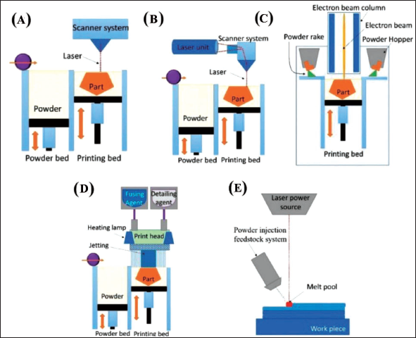
Before being fused by an electron beam, the powder metal is pre-heated. During the printing process, support structures are not necessary in EBM. Multi-jet fusion (MJF) is a variation of the PBF method that provides high resolution to produce microfluidic devices. A thin layer of powder is applied to the print bed, which has been pre-heated earlier to a consistent temperature. The fusing agent and detailing agent are then poured into specified parts of the powder bed using a thermal inkjet system, according to print requirements. After that, the print bed is subjected to an IR light, which allows the powder to fuse in certain areas (Figure 22D). A radiation-absorbing substance is introduced into the powder bed as the fusing agent. 140 Direct energy deposition (DED) is yet another 3D printing technique based on powder stock melting (Figure 22E). As a tweak to the PBF process, the DED process involves the continuous blowing of powder towards a high-energy laser source. 17 Although PBF has not been fully explored to the development of microfluidic devices, there have been few attempts in this direction. Datsiou et al. 141 have utilised the laser-based PBF method to fabricate fluidic channels with soda lime silica glass. A commercial LPBF system has been utilised to process the glass powder. A fibre laser with a wavelength of 1,064 nm selective melts3powder particles in layers of specified thickness in this system. To allow the highest particle size, a thickness of 70 µm is used. Slices of an STL model are taken at 70 µm intervals through its thickness to define the laser trajectories. The platform is shifted vertically at the end of each increment to enable an additional powder layer to be deposited, and the procedure is repeated until the complete 3D part is completed. Because of their excellent adherence to glass and high service temperature, high-purity (99.8%) alumina discs are chosen as substrates. During manufacture, the substrate is kept at 250°C to eliminate thermal gradients inside the produced pieces. Argon flow ensures an inert atmosphere inside the chamber. PBF is the most common 3D printing technology due to the high capability to reuse the powder particles, production pace, robust functional components, cost-effectiveness, no or minimal support structures, diverse fields of application and a vast range of suitable materials.
Microfluidic devices fabricated through PBF technology
Liu et al. 142 have developed a unique electrochemical additive manufacturing system design for printing mesoscale metal objects, based on the Meniscus-guided electrodeposition technique (Figure 23A). To maintain a consistent mesoscale meniscus, a microfluidic technology known as the fountain pen feed system is used. The proposed design enables for passive regulation of uninterrupted electrolyte supply at the printing tip during the printing process without liquid leakage, allowing the fountain pen feed system to automatically adjust the meniscus’s stability. The fountain pen feed system is a microfluidic system; made up of major channel components as well as the comb structure. Due to gravity and capillary action, the electrolyte flows through the primary channel to the printing head tip during the printing process. At the same time, air can flow through the primary channel into the reservoir, generating requisite back pressure for the flow of electrolyte continuously to the print head’s tip and the metal ions within the meniscus are deposited on the substrate when a positive voltage is placed between the working electrode and the substrate. The materials are then deposited at the specified spots to produce the required structure as the meniscus moves with the printing head along a programmed route. This research has paved the way for more advanced microfluidic systems to be developed in the future, allowing for improved printing resolution. Multi-layered thin glass porous channels have been fabricated by Datsiou et al. 141 With optical microscopy, the homogeneity of height and thickness of wall has been measured qualitatively as well as quantitatively; two specimens have been analysed per combination of characteristics to verify repeatability, with 10 equidistant measurements per specimen for wall thickness. The thickness homogeneity is defined by the coefficient of variation for each specimen being less than 10%. For energy densities more than ED27 J mm−2, good-quality walls are produced. The thin walls are created by repeating a laser scan in individual layers; their thickness is thus proportional to the width of the melt pool and this provides insight into the resolution feasible for more complicated structures created by LPBF. The chosen energy density has been found to be linearly proportional to wall thickness.
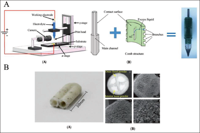
Biological applications
The ability of a laser PBF methodology to successfully form structures of glass with significant design intricacy which is impossible to achieve with traditional glass forming methods has been shown by Datsiou et al. 141 In their proposed work, process maps for the development of thin walls and solid cubes are created, and they can be used to guide the formation of any micro/nano-scale glass feature. The SLM 3D-printing technology can produce mesoscale structures in glass with features as small as 0.5 mm. PBF’s highly porous enclosed glass channels can be used as tissue engineering scaffolds (Figure 23B(a)). This is a significant advancement over traditional glass forming methods since it allowed for greater flexibility in building complicated 3D structures. 3D Printing technology has been used to automatically manufacture rapid-disintegrating medication delivery devices with loose powders based on CAD models. 127 A customised binder jet 3D-printing procedure is used to create a drug delivery device with internal compartments (Figure 23B(b)). 127 The drug delivery method has a cylindrical tablet made of fused powder on the outside. The interior of the tablet is divided into multiple compartments by fused powder walls, each of which is filled with loose medication powder. The minimum feature in the tablet’s lateral dimension is observed to be roughly 1 mm in diameter. With a mean dissolution time of roughly 23 seconds and a mean wetting time of 68 seconds, this 3D-printed medication tablet demonstrates acceptable pharmacological characteristics. It has a quick burst release, delivering almost 98% of its pharmacological load in less than 2 minutes. This is an important sector of research where PBF processes can play a major role in future.
Major challenges
One of the drawbacks of using powder 3D-printer-yielded systems for microfluidics is the poor surface finish and high porosity caused due to low resolving capacity. Despite the fact that newer powder-3D printing techniques, like MJF technology, allow the generation of components having low porosity and resolution up to 250 µm, significant post-processing dependence is there to improve surface characteristics. Further, MJF currently is impractical to work on transparent base materials. Powder-3D printing is susceptible to subsurface depletion zones and porosity, which can result in surface unevenness. Not-so-strong connection of the microfluidic device with the base material for sealing, results in undulations and poor surface characteristics which in turn can cause fluid leakage from the microfluidic chips. Also, optical transparency of 3D-printed microfluidic chips is a desirable property which is currently a challenging task to get out of PBF processes. Table 3 summarises the challenges and drawbacks of the available 3D printing technologies in biological applications and the potential research scopes.
Summary of the challenges encountered in biological applications of various 3D printing technologies and the future outlook.
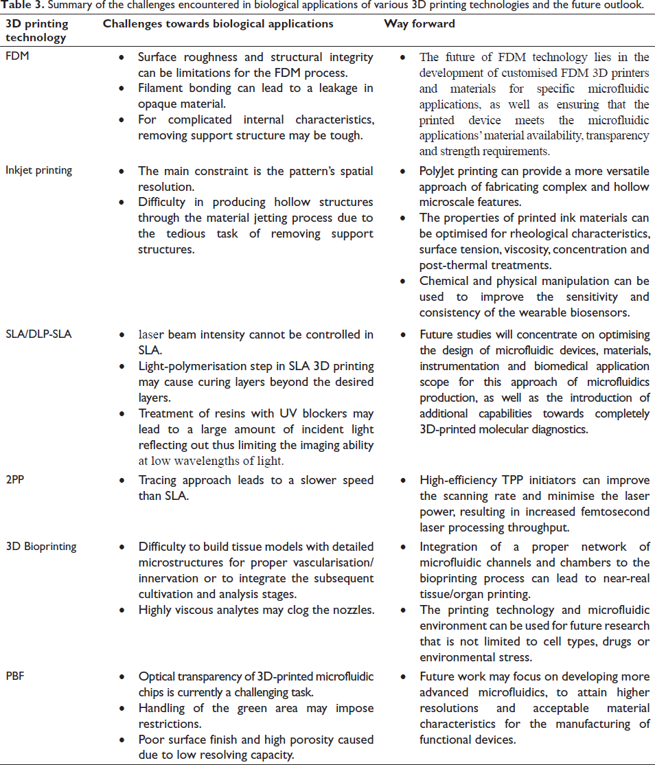
Summary and future perspectives
SLA fabrication is characterised by high surface resolution and low cost due to the comparatively reduced necessity of the liquid phase. One of the disadvantages of SLA is that the laser beam intensity cannot be controlled. The light-polymerisation step in SLA 3D printing (specifically during the printing of transparent resins) may cause curing layers beyond the desired layers. As a solution to this issue, resins are often treated with UV blockers, but again, this may lead to a large amount of incident light reflecting out thus limiting the imaging ability at low wavelengths of light. Whereas in a DLP 3D printer, the operator can adjust the power of UV light and hence manage the curing of resin. In coming times, 3D printing may open the possibility of quick iteration of different clamping systems and pre-programmed integration with manipulators.
The advantage of 2PP is that it allows for higher resolution spot size while reducing the need for an inert gas atmosphere. However, because of the tracing approach, the speed is slower than SLA. High-efficiency TPP initiators can improve the scanning rate and minimise the laser power, resulting in increased femtosecond laser processing throughput.
DLP-SLA takes a small amount of resin in the vat. In comparison to DLP 3D printing, SLA technology offers high accuracy and the print quality is superior because the resin is cured (hardened) from point to point. Future studies will concentrate on optimising the design of microfluidic devices, materials, instrumentation and biomedical application scope for this approach of microfluidics production, as well as the introduction of additional capabilities towards completely 3D-printed molecular diagnostics.
Inkjet printing is defined by high quality and precision, as well as its quick build speed and capability to print a variety of materials. The main constraint is the pattern’s minimum size (spatial resolution). The properties of printed ink materials can be enhanced further by optimising rheological characteristics, surface tension, viscosity, concentration and post-thermal treatments. Chemical and physical manipulation can be used to improve the sensitivity and consistency of the fundamental features of wearable biosensor applications.
The advantages of FDM lie in good building speed, low cost, high accuracy, flexibility and achievable structural complexity. Surface roughness and structural integrity can also be limitations for the FDM process in the fabrication of microfluidic devices. Also, due to filament bonding, there is a leakage in opaque material. For complicated internal characteristics, removing the support structure may be tough. The future of FDM technology lies in the development of customised FDM 3D printers and materials for specific microfluidic applications, as well as ensuring that the printed device meets the microfluidic applications’ material availability, transparency and strength requirements.
PBF printing methods are the most popular 3D printing technologies. PBF is advantageous in terms of reduced material waste and flexibility. However, when compared to other technologies PBF approaches are frequently thought to be slow. Any material that can be atomised into powder by a gas or plasma can be employed in PBF. There are no restrictions for printing thin walls; nevertheless, the handling of the green area may impose restrictions. Also, the application of PBF processes towards the fabrication of microfluidic devices and biological applications is limited currently. Future work may focus on developing more advanced microfluidics, to attain higher resolutions and acceptable material characteristics for the manufacturing of functional devices.
Bioprinting can be preferred where biocompatibility is a prerequisite. 3D bioprinting also allows flexibility and integrated structures on the micro/nanoscale. The printing technology and microfluidic environment can be used for future research that is not limited to cell types, drugs or environmental stress.
Author contributions
Ranamay Saha: Conceptualisation, writing original draft, visualisation, formulation of schematics; Sagnik Sarma Choudhury: Editing manuscript; Moloy Sarkar and Hemant Kumar: Editing and formulation of schematic diagrams; Geeta Bhatt and Shantanu Bhattacharya: Providing insight into fabrication techniques, supervision and review.
Footnotes
Declaration of Conflicting Interests
The authors declare that they have no known competing financial interests or personal relationships that could have appeared to influence the work reported in this article.
Funding
The authors received no financial support for the research, authorship and/or publication of this article.