
Abstract

Introduction
Posterior malleolar (PM) fractures occur in more than one-third of all ankle fractures, are typically caused by high-energy rotational forces, and are associated with poorer outcomes than ankle fractures without a PM component. 1 Although many PM fractures may be treated nonoperatively, relative indications for surgery include fragment size >25% of the articular surface, displacement >2 mm, or persistent instability following other fracture or syndesmotic fixation. 2
Several methods have been described for the fixation of PM fractures, including posterior plating, posterior-to-anterior (PA) screw fixation, and anterior-to-posterior (AP) screw fixation. 3 AP fixation via a percutaneous approach or extending existing approaches is amenable to supine positioning and eliminates the need for additional posterior incisions. Recently, fixation using AP lag screws with additional oblique positional screws has been shown to have comparable strength to posterior plating in a biomechanical model. 4
This technique tip describes the fixation of large PM fragments in the setting of bimalleolar or trimalleolar fractures using a combination of AP parallel and oblique screws, offering stable fixation without the risks and potential morbidity of posterior plating.
Indications and Contraindications
This technique is an option for bimalleolar or trimalleolar fracture patterns with a single, sufficiently large PM fragment able to accommodate 3-4 AP transverse and oblique screws with reliable purchase. Case examples are shown in Table 1 and Figures 1 to 3. Relative contraindications include significant posterior comminution, osteoporotic bone, or smaller PM fragments not suitable for screw fixation.
Included Patient and Fracture Characteristics.
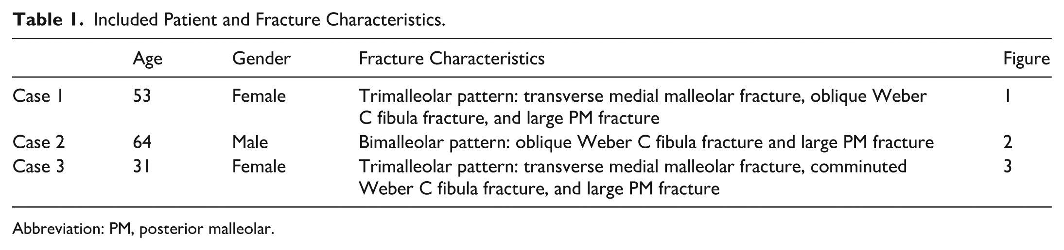
Abbreviation: PM, posterior malleolar.

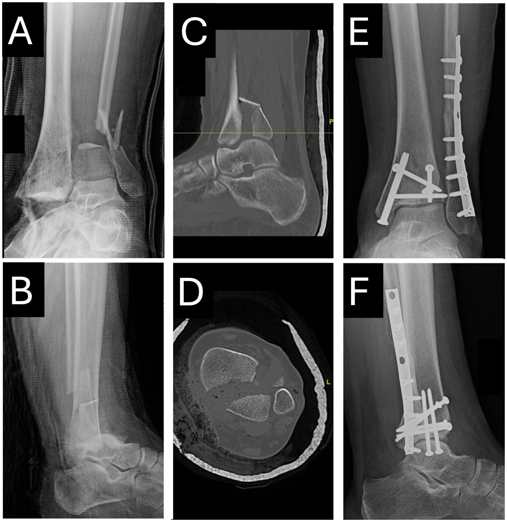
Trimalleolar ankle fracture pattern with a comminuted distal fibula fracture, displaced medial malleolar fracture, and large posterior malleolar fracture, as demonstrated on mortise (A) and lateral (B) radiographs, as well as on sagittal (C) and axial (D) CT imaging. One-year postoperative weightbearing radiographs are shown on mortise (E) and lateral (F) views. CT, computed tomography.

Bimalleolar ankle fracture pattern with an oblique distal fibula fracture and large posterior malleolar fracture with medial extension, as demonstrated on mortise (A) and lateral (B) radiographs, as well as on sagittal (C) and axial (D) CT imaging. Three-month postoperative weightbearing radiographs are shown on mortise (E) and lateral (F) views. CT, computed tomography.
Trimalleolar ankle fracture pattern with a comminuted distal fibula fracture, displaced medial malleolar fracture, and displaced large posterior malleolar fracture, as demonstrated on mortise (A) and lateral (B) radiographs, as well as on sagittal (C) and axial (D) CT imaging. Nine-month postoperative weightbearing radiographs are shown on mortise (E) and lateral (F) views. CT, computed tomography.
Technique
Preparation and Visualization
In supine position with a calf or thigh tourniquet, standard longitudinal medial and/or lateral incisions are made, depending on the need for medial and/or lateral malleolar fixation (Figure 4). Visualization and mobilization of the PM fragment can be achieved through either the medial or lateral incisions. For a distal fibula fracture, a transfibular approach with distraction of the fibular fracture line with a K-wire distractor or bone spreader allows for direct visualization of the PM fragment and removal of any incarcerated fragments (Figure 5A). For a medial malleolar fracture, the medial fragment can be retracted distally, or the medial dissection extended, to expose the PM fracture line at the plafond or along the medial cortex, respectively (Figure 5B). If articular reduction cannot be confirmed through the medial malleolus fracture line, arthroscopy may be implemented to visualize the PM fragment. Once the posterior fracture line is visualized, the fracture can be mobilized and sharp debridement can be performed. Anatomic reduction of the distal fibula to length is critical prior to attempting reduction of the PM fragment. The fibula may be provisionally stabilized with clamps or K-wires, or definitively fixed, although assessment of PM reduction on lateral fluoroscopy can be difficult with lateral hardware in place.
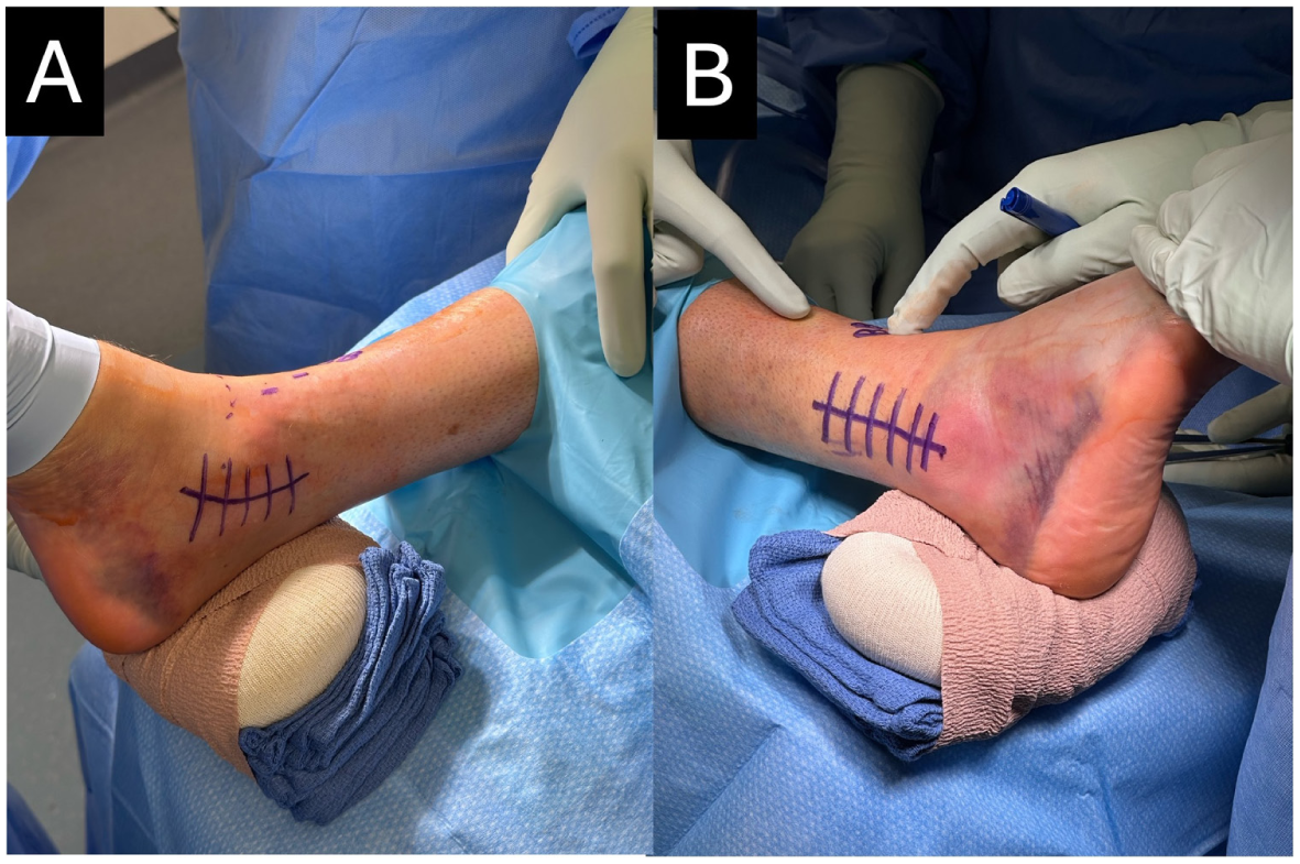
Medial (A) and lateral (B) incision markings for the visualization, reduction, and fixation of the large posterior malleolar fragment through a medial or lateral malleolar fracture.

Visualization and debridement of the posterior malleolar fracture line may be performed laterally through distraction of the fibular fragments (A) or medially by extending the medial incision (B). The posterior malleolus is then reduced with a periosteal elevator (C) or point-to-point reduction clamps (D) and held with K-wires (B, D).
Reduction and Fixation With AP Screws
Reduction of the PM fragment can be obtained using manual pressure from a periosteal elevator (Figure 5C), dental pick, or point-to-point reduction clamps (Figure 5D). One or more Kirschner wires (K-wires) are then used to hold the reduction (Figure 5B). Two 3.5-mm AP cortical screws are placed parallel to the joint surface approximately 1 cm above the joint line in a lag-by-technique fashion. Positional screws, instead of lag screws, may be preferable when the fracture is already anatomically compressed and when the fragment is smaller or the bone quality is poor. These screws may be placed through the pre-existing medial and lateral incisions or percutaneously through the anterior tibia using fluoroscopy to guide screw start point and trajectory (Figure 6, A-C). Percutaneous screw placement requires small 1 to 1.5 cm incisions and careful dissection to bone, with identification and protection of the superficial and deep peroneal nerve branches. Two additional 3.5-mm oblique positional screws, with medial and lateral start points, are placed from 3 to 4 cm above the joint line aimed toward the tip of the PM fragment (Figure 6, D and E). The medial and/or lateral fragments can then be reduced and fixed as appropriate (Figure 6F). The syndesmosis is stressed under fluoroscopy with external rotation and is stabilized if needed. The incisions are closed in standard layered fashion (Figure 7).

Fluoroscopic views of the AP parallel and oblique screw fixation technique. (A) The first cortical screw is inserted in lag configuration parallel to the plafond. (B) The K-wire is removed, and a second cortical screw is inserted in lag configuration parallel to the plafond. (C) AP view demonstrating the position of the 2 parallel lag screws. (D) A third cortical screw is inserted in positional configuration at an oblique angle. (E) A fourth cortical screw is inserted in positional configuration at an oblique angle. (F) AP view demonstrating the complete fixation of the posterior malleolus with 4 cortical screws and plate fixation of the distal fibula.

Skin closure demonstrating the location of the lateral longitudinal and anterior percutaneous incisions for screw placement.
Postoperative Protocol
Patients are placed in a posterior splint with side gussets and remain nonweightbearing initially to protect the soft tissues during wound healing. If syndesmotic fixation is not required and the bone quality is adequate, weightbearing “as tolerated” in a controlled ankle motion (CAM) boot begins at 2 weeks. If syndesmotic fixation is performed or if the bone quality is poor, nonweightbearing is maintained for 6 weeks.
Discussion
Traditionally, posterior plating has been the standard for fixation of large PM fractures because of reports of superior biomechanical stability and ease of exposure and reduction. 3 However, there are potential drawbacks to posterior plating, as the additional posterior incision or dissection to visualize the fragment required has been associated with sural nerve injury, flexor hallucis longus adhesions, damage to posteromedial neurovascular structures, and increased postoperative stiffness.5,6 Additionally, prone positioning for the posterior approach poses challenges in treating concurrent medial fractures and syndesmosis reduction and fixation, and is associated with increased risks in certain patients, including nerve injuries, cardiovascular compromise, ocular injuries, and airway complications.7,8
The described technique using AP screw-only fixation allows for treatment of select PM fractures with supine positioning and percutaneous or existing medial and lateral exposures. Unlike previously described AP screw constructs that rely solely on 2-3 screws placed parallel to the plafond, this technique incorporates additional oblique screws, creating a multiplanar fixation strategy that has been shown to be biomechanically comparable to posterior plating in an early weightbearing cadaveric model. 4
Successful application of this technique requires familiarity with ankle approaches, careful soft tissue handling, experience with indirect fracture manipulation, and the ability to obtain high-quality fluoroscopic images.
At our institution, this AP oblique screw technique has successfully been implemented in multiple patients without hardware failure or reoperation. Although these early results are promising, larger patient series and long-term follow-up are needed to confirm the durability of fixation and to evaluate outcomes relative to posterior plating.
Supplemental Material
sj-pdf-1-fao-10.1177_24730114261435960 – Supplemental material for Anterior to Posterior Oblique Screw Fixation of Posterior Malleolar Fractures: Surgical Technique Tip
Supplemental material, sj-pdf-1-fao-10.1177_24730114261435960 for Anterior to Posterior Oblique Screw Fixation of Posterior Malleolar Fractures: Surgical Technique Tip by Phillip Schmitt, Jonathan Liu, Michael Shipp, Kathryn Segal, Amanda Galambas, Brad Blankenhorn and Raymond Hsu in Foot & Ankle Orthopaedics
Footnotes
Ethical Considerations
Our institution does not require ethical approval for reporting individual cases or case series.
Consent to participate
Informed consent was obtained verbally from all participants for anonymized patient information and radiographs to be published in this article.
Funding
The authors received no financial support for the research, authorship, and/or publication of this article.
Declaration of Conflicting Interests
The authors declared no potential conflicts of interest with respect to the research, authorship, and/or publication of this article. Disclosure forms for all authors are available online.
Data availability Statement
All data generated or analyzed during this study are included in this published article.
References
Supplementary Material
Please find the following supplemental material available below.
For Open Access articles published under a Creative Commons License, all supplemental material carries the same license as the article it is associated with.
For non-Open Access articles published, all supplemental material carries a non-exclusive license, and permission requests for re-use of supplemental material or any part of supplemental material shall be sent directly to the copyright owner as specified in the copyright notice associated with the article.