
Abstract
This is a visual representation of the abstract.
Introduction
Third-generation minimally invasive hallux valgus correction involves deformity correction through a percutaneous distal first metatarsal osteotomy that is held with 2 fully threaded screws. 5 Key to the technique is that the more proximal screw passes through the lateral cortex of the proximal fragment to achieve stability. The metatarsal procedure is usually paired with a medial closing osteotomy of the proximal phalanx.
Positioning and imaging can be challenging components of this technique, with most authors using supine position with a c-arm that is flipped back-and-forth between anterior-posterior (AP) and lateral views while the foot remains stationary.1,2,4,6,7 One group recently described use of the lateral position. 3
The need to swap back and forth between views for each step causes these cases to be imaging- and time-intensive, with multiple shots obtained simply to get a good radiograph prior to even evaluating positioning of the osteotomy or hardware. It can additionally be challenging to hold and fixate the osteotomy while swapping between views.
We describe a technique involving the use of 2 c-arms positioned at 90 degrees with respect to each other to obtain simultaneous orthogonal views. This allows performance of third-generation minimally invasive correction of hallux valgus without manipulation of the foot or fluoroscopic imaging intensifier for the duration of the case.
Operative Technique
Positioning and setup
Positioning of the extremity and arrangement of the room are key (Figure 1). The patient is initially positioned supine with an ipsilateral gluteal bump and the heel hanging just off the table. The foot of the table is then hinged down at the knee, and the nonoperative leg is allowed to drop. An ankle arthroscopy positioner is used to support the operative thigh such that the tibia is suspended 45 degrees to the floor and the foot hangs in the air. The large c-arm is brought in from the operative side with a radiolucent triangle or foot positioner secured to it. Of note, we use a custom-built foot positioner that is described in the Supplementary Images, but a radiolucent triangle works as well. The foot is placed on the triangle or positioner with the heel 10 cm above the c-arm receiver and the foot angled in 30 degrees of dorsiflexion relative to the receiver. The mini c-arm is brought in from the foot with the receiver flush against the lateral foot. The foot is then sterilely prepped and draped, and the c-arms (and triangle/positioner) are covered in sterile drapes. The surgeon stands on the medial side of the foot to which he or she has full access.

Operating room setup. (A) The radiolucent triangle or foot positioner is secured to the receiver side of the large c-arm. Whichever method is used, the heel is elevated off the receiver by 10cm and the foot is in 30 degrees of dorsiflexion relative to the receiver. The elevation allows for clearance of the mini c-arm away from the large c-arm receiver for a clear lateral view. The dorsiflexion allows for a true anterior-posterior view of the first metatarsal. (B) The operative table is flexed at the knee to 90 degrees allowing the nonoperative extremity to flex at the knee and fall out of the way. The operative extremity is supported at the thigh by an ankle arthroscopy positioner, and the foot is supported by the radiolucent triangle or foot positioner on the large c-arm. (C) The mini c-arm is brought in from the foot of the bed with the receiver flush against the lateral border of the foot. (D) The foot is sterilely prepped and draped. The c-arms are draped using standard drapes, with the radiolucent triangle or foot positioner included in the drape for the large c-arm. (E) Surgeon’s perspective. The setup allows full access to the medial border of the foot as well as clear views of the large and mini c-arm screens. (F) View of the procedure from the foot of the bed. The mini c-arm is positioned to obtain lateral views and the large c-arm is positioned to obtain anterior-posterior views. The medial border of the foot is left unobstructed to facilitate instrumentation.
Procedure
Every step of the procedure is performed using simultaneous anteroposterior and lateral imaging without manipulation of the c-arms or extremity (Figures 2 and 3).

Metatarsal osteotomy and proximal screw placement. (A-D) Using simultaneous anterior-posterior and lateral imaging, a 2.5mm drill bit is passed from the proximal medial base of the metatarsal through the lateral cortex of the metatarsal just proximal to the metatarsal neck. The drill bit is exchanged for a wire, the length of the screw is estimated using a depth gauge or ruler, and a 4.0mm screw is advanced to just beyond the lateral cortex. (E-F) An osteotomy is made at the metatarsal neck using the 2mm x 20mm burr, and the correction is obtained and maintained using an elevator. (G-H) Once simultaneous anterior-posterior and lateral imaging confirms acceptable reduction, the K-wire is malleted up the shaft of the screw into the metatarsal head to lock in the correction, and the screw is advanced up the wire to the appropriate depth.

Placement of the distal metatarsal screw and phalangeal osteotomy. (A-D) The distal metatarsal screw is placed just distal and parallel to the proximal screw. A solid 2.0mm drill bit is used to create a hole for the screw, the bit is exchanged for a wire, the wire length is measured, and a cannulated 3.0mm screw is inserted over the wire. (E-H) The medial closing wedge phalangeal osteotomy is performed using a 2.0mm x 12mm burr taking care to leave the lateral cortex intact. The osteotomy is closed and a 2.0mm drill bit is used to create a hole for the screw from the medial base of the phalanx to the distal lateral cortex of the phalanx. The bit is exchanged for a wire, the wire length is measured, and a cannulated 3.0mm screw is inserted over the wire.
Five stab incisions are made on the medial border of the foot using fluoroscopic guidance: 2 for the osteotomies and 3 for the screw start points. A curved elevator is used to elevate the periosteum dorsally.
A solid 2.5-mm drill bit is then used to establish a hole for the more proximal metatarsal screw, running from the medial cortex proximally out the lateral cortex just proximal to the metatarsal neck (Figure 2A and 2B). A Kirschner (K)-wire is inserted into the hole, and the length of this screw is estimated (Figure 2C). A 4.0-mm screw is inserted over the K-wire slightly beyond the lateral cortex (Figure 2D).
The metatarsal osteotomy is then made using a 2.0 mm × 20 mm burr at the metatarsal neck (Figure 2E). Correction is performed using an intramedullary elevator (Figure 2F). Once simultaneous orthogonal images confirm optimal correction, the K-wire is malleted up the screw into the metatarsal head (Figure 2G). The screw is then advanced into final position (Figure 2H).
A second metatarsal screw is placed. This second screw is just distal and parallel to the first. A solid 2.0-mm drill bit is used to create a hole for the screw (Figure 3A and 3B), the drill is exchanged for a wire (Figure 3C), the wire length is measured, and a 3.0-mm screw is inserted over the wire (Figure 3D).
The medial closing wedge phalangeal osteotomy is performed using a 2.0 × 12-mm burr taking care to leave the lateral cortex intact (Figure 3E). The osteotomy is closed and a 2.0-mm drill bit is used to create a hole for the screw from the medial phalangeal base to the distal lateral phalangeal cortex (Figure 3F). The bit is exchanged for a wire, the wire length is measured (Figure 3G), and a 3.0-mm screw is inserted over the wire (Figure 3H).
A percutaneous lateral release is performed. A Beaver blade is inserted from dorsal to plantar under fluoroscopic guidance at the lateral aspect of the first metatarsophalangeal joint. The blade is inserted intracapsular with the sharp surface angled laterally and used to divide the lateral head of the flexor hallucis brevis (lateral sesamoid phalangeal ligament).
Discussion
Imaging is one of the more challenging technical components of third-generation minimally invasive correction of hallux valgus, wherein repeated swapping between orthogonal views is required to ensure appropriate osteotomy and K-wire placement.
The described technique enables the surgeon to perform the third-generation correction without repositioning the extremity or imaging intensifier for the duration of the case. AP and lateral views can be obtained simultaneously.
Of note, another difficult aspect of the third-generation technique is placement of the K-wires for the partially threaded screws, as the wires are small diameter and prone to “skiving.” Moreover, if a K-wire is inserted into an incorrect position, it can be difficult to create a second nearby hole if only a small adjustment is needed. Because the 2-c-arm technique makes orthogonal imaging instantaneous and easy, we were able to convert to an all-solid-drill technique, simply advancing the drill only small amounts at a time and not until we were completely happy with the trajectory on both views. This further simplifies the case.
At our institution, the time savings from this dual c-arm and all-solid-drill technique have been significant. Although more initial work is involved in setting up the room and positioning the extremity, the procedure itself is simplified, more reproducible, and easier to teach.
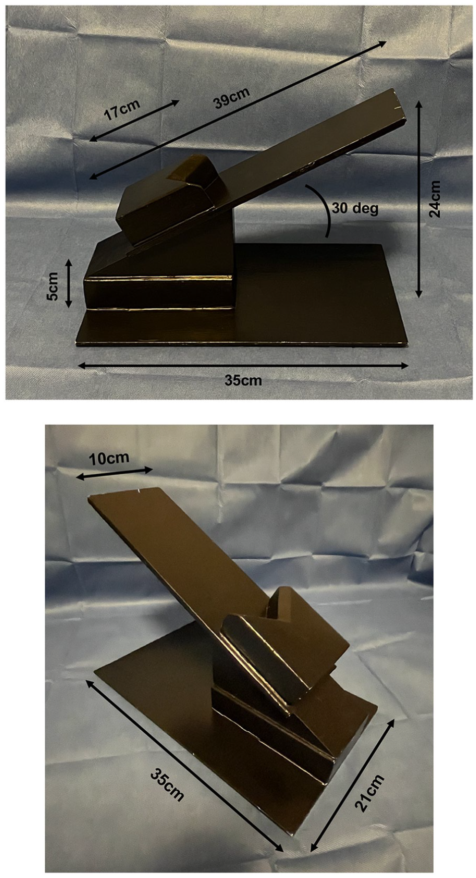
Dimensions of the custom-built foot positioner.
Supplemental Material
sj-docx-1-fao-10.1177_24730114241308574 – Supplemental material for Orthogonal C-arms for Third-Generation Minimally Invasive Correction of Hallux Valgus: A Technique Tip
Supplemental material, sj-docx-1-fao-10.1177_24730114241308574 for Orthogonal C-arms for Third-Generation Minimally Invasive Correction of Hallux Valgus: A Technique Tip by Daniel D. Bohl, Derek M. Klavas, Alaa Mahmoud and Eric C. Bellinger in Foot & Ankle Orthopaedics
Footnotes
Declaration of Conflicting Interests
The author(s) declared no potential conflicts of interest with respect to the research, authorship, and/or publication of this article. Disclosure forms for all authors are available online.
Funding
The author(s) received no financial support for the research, authorship, and/or publication of this article.
Ethical Approval
Ethical approval was not sought for the present study.
References
Supplementary Material
Please find the following supplemental material available below.
For Open Access articles published under a Creative Commons License, all supplemental material carries the same license as the article it is associated with.
For non-Open Access articles published, all supplemental material carries a non-exclusive license, and permission requests for re-use of supplemental material or any part of supplemental material shall be sent directly to the copyright owner as specified in the copyright notice associated with the article.