
Abstract
Exclusive liquid repellency (ELR) describes an extreme wettability phenomenon in which a liquid phase droplet is completely repelled from a solid phase when exposed to a secondary immiscible liquid phase. Earlier, we developed a multi-liquid-phase open microfluidic (or underoil) system based on ELR to facilitate rare-cell culture and single-cell processing. The ELR system can allow for the handling of small volumes of liquid droplets with ultra-low sample loss and biofouling, which makes it an attractive platform for biological applications that require lossless manipulation of rare cellular samples (especially for a limited sample size in the range of a few hundred to a few thousand cells). Here, we report an automated platform using ELR microdrops for single-particle (or single-cell) isolation, identification, and retrieval. This was accomplished via the combined use of a robotic liquid handler, an automated microscopic imaging system, and real-time image-processing software for single-particle identification. The automated ELR technique enables rapid, hands-free, and robust isolation of microdrop-encapsulated rare cellular samples.
Introduction
Single cells have found various important applications, such as in the study of cancer heterogeneity,1–3 developmental biology,4,5 neurobiology,2,6 and immunology.7,8 There is growing interest in identifying and isolating specific single cells from a heterogeneous biological sample to discover the unique cellular traits underlying biological heterogeneity. The isolation of single cells from a small sample pool (e.g., a few hundred to a few thousand cells), however, remains a highly challenging endeavor. Although current single-cell isolation techniques like limiting dilution, fluorescence-activated cell sorting (FACS), 9 and microfluidics10–12 can allow for the isolation of single cells at relatively high throughput, they require a relatively large sample volume and cell number to work with and could struggle to isolate single cells from a very limited sample size, which makes them unsuitable for rare-cell applications like circulating tumor cell (CTC) research.13,14 Single-cell printing techniques (e.g., from cytena) were developed to operate with only a few microliters of sample volume to isolate hundreds of single cells into microwell plates (e.g., 96- or 384-well plates) with a high yield (> 95%). The successful handling of minute amounts of samples requires an efficient liquid-handling technique that has very low loss during aspiration, transfer, and sample retrieval from culture. This is generally difficult using traditional single-liquid-phase liquid-handling and storage equipment such as multiwell plates. Aqueous liquids generally exhibit adherence to these surfaces, and thus any liquid transfer would result in residual liquid being left behind. Sample loss can be further aggregated due to nonspecific cell adhesion on solid surfaces and/or detrimental evaporation or condensation when cell culture is involved. 15 Although a variety of specialized multi-liquid-phase platforms have been developed for efficiently manipulating small amounts of cell samples without significant loss, such as droplet microfluidics, 16 they are usually based on a closed-system design, 17 which makes external access for individual cell manipulation and retrieval difficult,18,19 and also require costly and complex devices and fluid control equipment. 20
Exclusive liquid repellency (ELR) describes the conditions of a solid–water–oil three-phase system that allows for complete repellency of an aqueous droplet from the solid phase, exhibiting a contact angle (CA) of 180° (
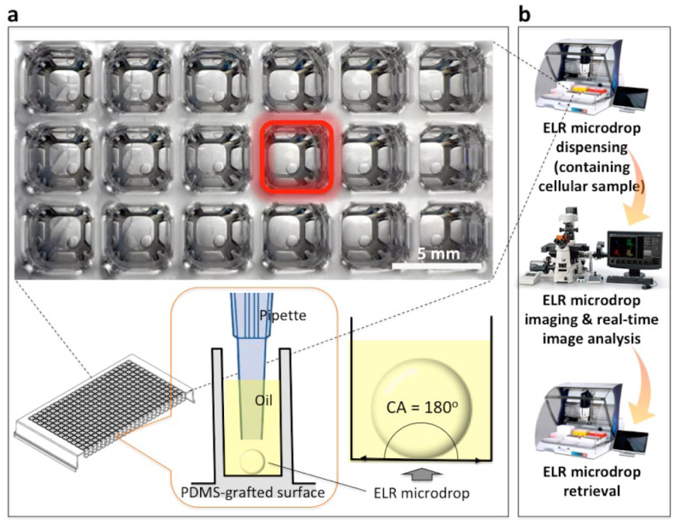
Schematic of exclusive liquid repellency (ELR) microdrop-based automated open microfluidic system. (
Materials and Methods
Conditions to Achieve ELR
In previous work, the physics and design rules for ELR were discussed.
21
In brief, in a solid–water–oil three-phase system, ELR can be achieved only if the interfacial energies (i.e., γS/W for solid–water, γS/O for solid–oil, and γW/O for water–oil) meet a boundary condition, that is, γS/O + γW/O ≤ γS/W for water in oil and γS/W + γW/O ≤ γS/O for oil in water. Determined by this principle, aqueous microdrops get completely repelled with a CA of 180° from polydimethylsiloxane (PDMS) surfaces under silicone oil (
Fabrication of PDMS-Grafted Well Plate
A standard 384-well plate (polystyrene, tissue culture treated by vacuum gas plasma, and nonpyrogenic; Corning, NY) was treated first with oxygen plasma (Plasma Surface Technology, 60 W, 3 min; Diener Electronic Femto, Ebhausen, Germany), then transferred into a vacuum desiccator for vapor phase deposition of PDMS–silane (1,3-dichlorotetramethylsiloxane, SID3372.0; Gelest, Morrisville, PA). 50 µL PDMS–silane was vaporized under reduced pressure in the desiccator by pumping down for 3 min, then condensed onto the surface of the well plate under vacuum at room temperature for 30 min. The PDMS-grafted well plate was thoroughly rinsed with ethanol (anhydrous, 99.5%) and deionized (DI) water, then dried with compressed air for use.
Preparation of Stable Fluorescence Bead Suspension
Fluorescence beads [melamine resin based, carboxylate modified, fluorescein isothiocyanate (FITC) marked, 12 µm average diameter, 90287-5ML-F; Sigma-Aldrich, St. Louis, MO] were used as model particles. The beads were dispersed in phosphate-buffered saline (PBS) containing 2 mg/mL collagen I (bovine, PureCol; Advanced BioMatrix, San Diego, CA) to give a stable suspension with a concentration of 1 bead/µL, showing no settling of the dispersed particles throughout time.
Results
Dispensing of Bead-Containing ELR Microdrops
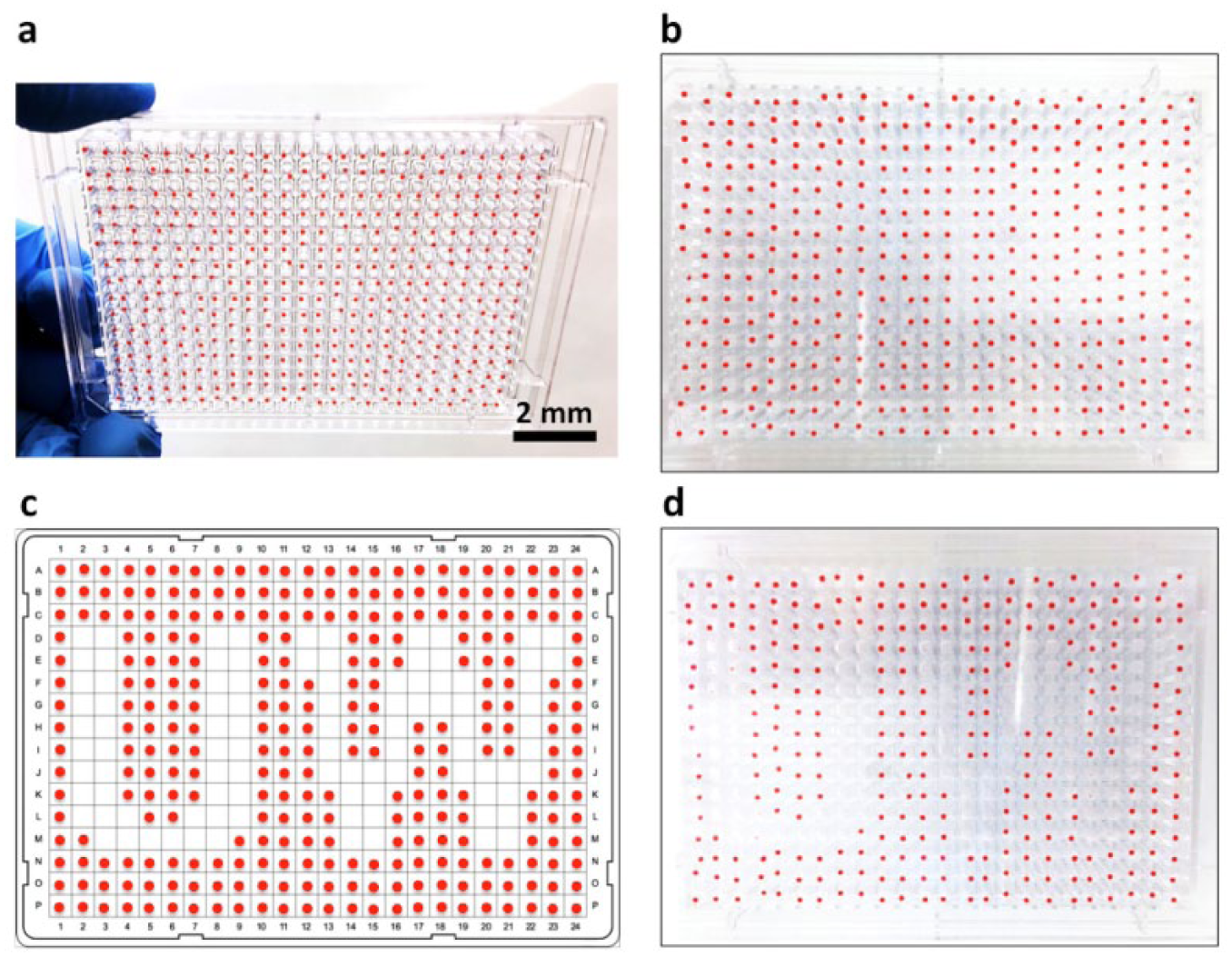
A robotic liquid handler (PIPETMAX; Gilson, Middletown, WI) was programmed for this task (
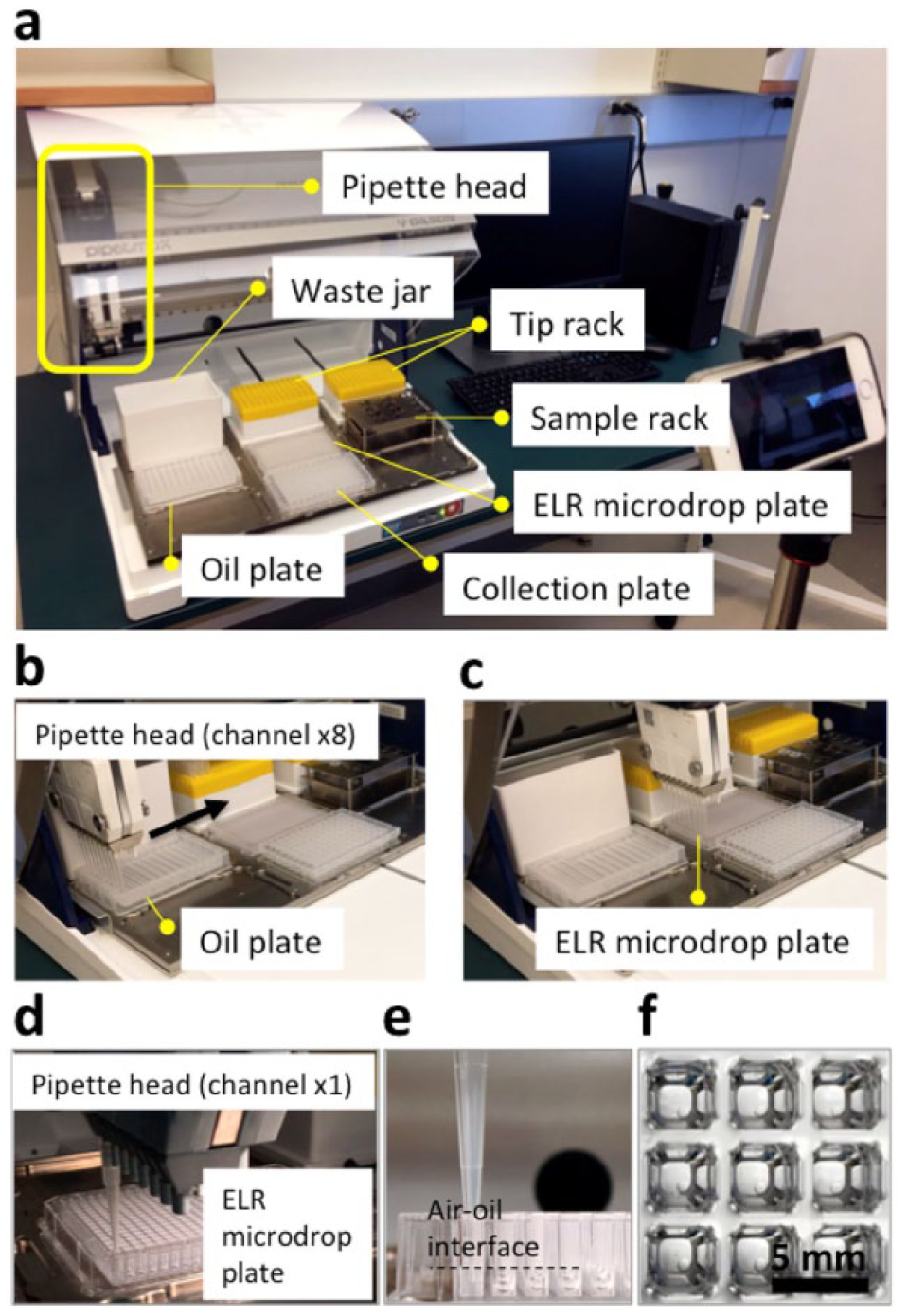
Exclusive liquid repellency (ELR) microdrop dispensing with pipette robot. (
Image-Based Microdrop and Bead Detection
The prepared ELR microdrop plate was imaged using a Nikon Ti-Eclipse widefield fluorescence microscope at 4× magnification. A single bright-field (BF) image (2 ms exposure; Fig. 3b and 3c) and a 7-slice z-stack in the 488 nm fluorescence channel (100 ms exposure, Δz = 150 µm;
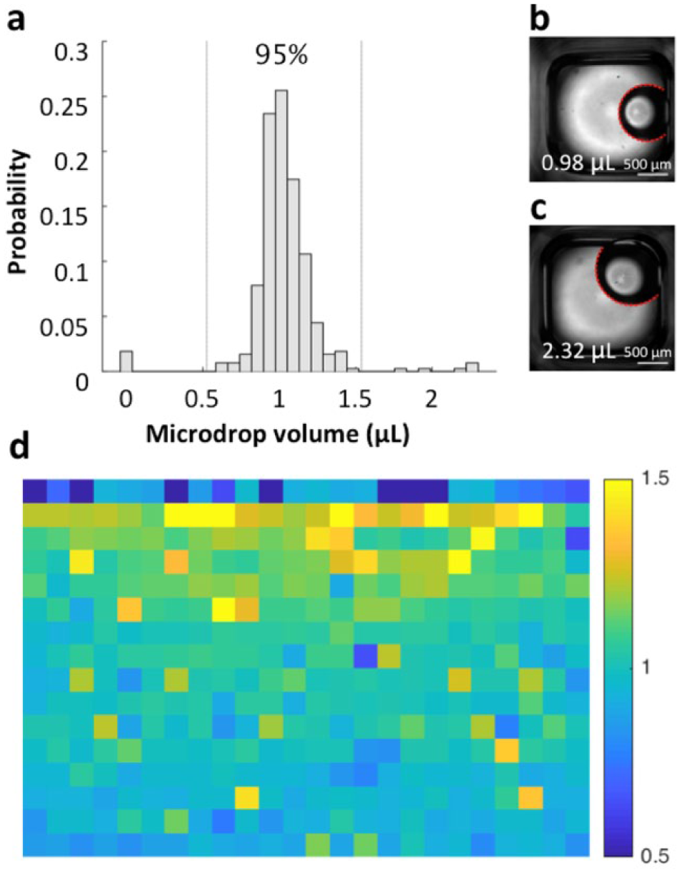
Microdrop volume. (
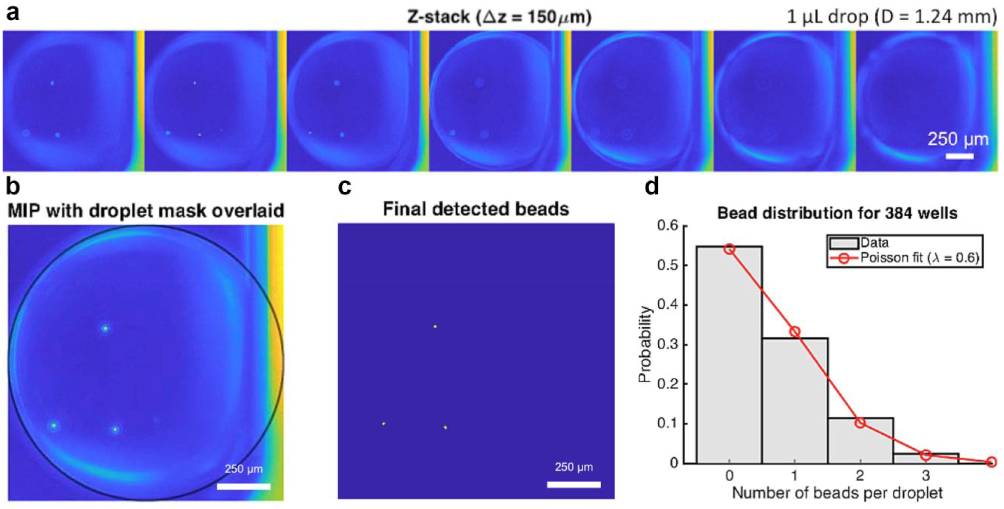
Bead detection. (
Fully automated bead detection was performed in real time during image acquisition using a custom-built program written in MATLAB (MathWorks, Natick, MA). The detection algorithm consisted of a two-step process. The first step was to identify and segment the boundary of each microdrop in the BF images (
Suppl. Fig. S1
). Its purpose was to mitigate false-positive detection by requiring that beads are located within the microdrop region. BF images were masked with an intensity threshold using the triangle method,
22
and the central region corresponding to the illumination spot was isolated based on its large size. The convex deficiency of the spot (i.e., the difference between the region and its convex hull) largely consisted of pixels within the microdrop, although it also included many unwanted small regions. Most of these pixels were removed by morphological opening with a small structuring element (disk of radius 5), followed by intersection with the original spot edge. The final microdrop mask was generated by fitting a circle to the remaining edge pixels using a random sample consensus (RANSAC) fitting routine. Because remaining unwanted pixels were relatively few compared to those of the oil–water interface (i.e., the edge of each microdrop facing the well center), they were given zero weight using the RANSAC approach. The microdrop volume was calculated using the equation for a sphere with the fitted radius. The second step was to detect beads in the 488 nm fluorescence channel (
Bead detection was validated against a manual count of beads per microdrop by an image scientist blinded to the automated results. One type of validation was to consider bead detection as a binary process (i.e., negative for zero beads and positive for at least one bead) and analyze the receiver operating characteristics (ROCs; Suppl. Fig. S2 ). ROC curves could be calculated by varying either the CNR threshold or area threshold. Because, however, the detection results were relatively insensitive to a reasonable range of minimum CNR, the area threshold was considered while keeping the CNR threshold constant at 10. The area under the curve (AUC) of the ROC curve was used to assess the overall quality of the automated approach. A second type of validation was to assess the exact number of beads detected per microdrop using the intraclass correlation coefficient (ICC; Suppl. Table S1 ).
Microdrop Retrieval
After identification with microscopy, the microdrops were registered with their location information on the ELR microdrop plate (
Microdrop retrieval. (
Discussion
The ELR microdrop-based open microfluidic system offers a set of characteristics enabling its use as a cell culture and screening platform,21,23 which includes (1) minimized media loss and interwell contamination via evaporation and condensation; (2) minimized sample loss and device fouling from sample loading, culture, transfer, and retrieval; (3) adjustable permeation of vital gases (e.g., oxygen and carbon dioxide); (4) full physical access and sample manipulation on device with external tools (e.g., pipettes); (5) compatibility with standard bioassay labware (e.g., well plates and culture dishes); and (6) low adoption barrier (i.e., easy to make and easy to use). By benefiting from automation enabled by a combined use of a robotic liquid handler and an imaging and real-time image analysis system, human labor and operator error can be significantly reduced ( Suppl. Table S2 ).
When preparing an ELR microdrop plate on the robotic liquid handler, liquid dispensing can be done with adjustable throughput by using different numbers of pipette channels (1 to 8 in this model study;
The distribution of microdrop volume was measured by fitting the detected oil–water interface (or edge of a microdrop) to a circle (
In preliminary experiments, we found that a minimum CNR of 10 and a minimum area of 10 pixels produced very accurate bead detection, so we use these values here. Any objects within the microdrop area that meet these thresholds are considered beads. Importantly, we also determined how the spacing of z-slices affects the accuracy, and we found that slices may be spaced up to 150 µm without significantly degrading the accuracy. This is helpful for acquiring the minimum number of z-slices in the interest of acquisition time (
As previously demonstrated, the number of beads per dispensed microdrop was expected to obey Poisson distribution.
21
Poisson distribution is described by the following equation: P (k events in interval) = e−λ(λk/k!), where P is the probability of occurrence with k events in interval (i.e., the number of beads per droplet), λ is the average events in interval (i.e., the concentration of bead suspension), and e is the base of natural logarithms. The automated results showed a fit of Poisson distribution with parameter λ = 0.6 bead/µL (
Owing to the advantages of underoil ELR, microdrops of interest after screening can be harvested and trans-ferred without loss with the protection of oil (
The combination of automated liquid handling, imaging, and real-time image analysis with the ELR-based microdrop system greatly improves the practicality and broad applicability of the technique in biomedical laboratories and clinics, where the highest impact is expected. Automation can release lab workers from laborious and repetitive experiments, which greatly increases the efficiency of assays and reduces inconsistency in data collection caused by operator errors.
Supplemental Material
DS_TECH853219 – Supplemental material for Automated System for Small-Population Single-Particle Processing Enabled by Exclusive Liquid Repellency
Supplemental material, DS_TECH853219 for Automated System for Small-Population Single-Particle Processing Enabled by Exclusive Liquid Repellency by Chao Li, David J. Niles, Duane S. Juang, Joshua M. Lang and David J. Beebe in SLAS Technology
Footnotes
Acknowledgements
We thank Dr. Scott Berry, Dr. John Guckenberger, and Dr. Jennifer Schehr for the early training on the robotic liquid handler and Ms. Crysta Frank for assistance on the test run of liquid-handling protocols.
Author Contributions
C.L. and D.N. contributed equally. C.L. and D.N. designed the research. C.L., D.N., and D.J. conducted experiments, and all authors interpreted the data; C.L., D.N., and D.J. wrote the manuscript, and all authors revised it.
Declaration of Conflicting Interests
The authors declared the following potential conflicts of interest with respect to the research, authorship, and/or publication of this article: D. J. Beebe holds equity in BellBrook Labs LLC, Tasso Inc., Stacks to the Future LLC, Lynx Biosciences LLC, Onexio Biosystems LLC, and Salus Discovery LLC. J. Lang holds equity in Salus Discovery LLC.
Funding
The authors disclosed receipt of the following financial support for the research, authorship, and/or publication of this article: This work is funded by NSF EFRI-1136903-EFRI-MKS, NIH R01 EB010039 BRG, NIH R01 CA185251, NIH R01 CA186134, NIH R01 CA181648, EPA H-MAP 83573701, the Prostate Cancer Foundation Challenge Award, the University of Wisconsin Carbone Cancer Center’s Cancer Center Support Grant P30 CA014520, and the Wisconsin Partnership Program Collaborative Health Sciences Grant.
Supplemental material is available online with this article.
References
Supplementary Material
Please find the following supplemental material available below.
For Open Access articles published under a Creative Commons License, all supplemental material carries the same license as the article it is associated with.
For non-Open Access articles published, all supplemental material carries a non-exclusive license, and permission requests for re-use of supplemental material or any part of supplemental material shall be sent directly to the copyright owner as specified in the copyright notice associated with the article.