
Abstract
This study investigates electromagnetic interference shielding and antibacterial activity of industrial polyester/viscose woven fabrics, including silver (Ag) treated yarns, to obtain multifunctional fabric. For this purpose, thin film-coated, nanoparticle-doped, and chemically treated yarns were used as weft in three different densities. Nine fabric samples and the control sample were woven under industrial conditions. As a result, the surface conductivity of the thin film-coated samples is significantly higher than the others in all the measurement directions. Also, these samples exhibit the best electromagnetic shielding efficiency of up to 64 dB in the 3–43 GHz frequency range. In addition, electromagnetic shielding efficiency reaches 83 dB when the samples are measured in multiple layers. The chemically treated samples exhibited better antibacterial activity, up to 74%. It was determined that the nanoparticle’s treatment type, position and density, and the number of fabric layers influence the performance properties.
Introduction
Nowadays, the increased electromagnetic (EM) pollution causes disturbances to nearby electronic apparatus and severely threatens people’s health. EM radiations influence human health and undesirably reduce the performance and lifetime of delicate electronic components. Therefore, high-performance EMI shielding materials are urgently needed to reduce electromagnetic pollution and effectively isolate the devices from EMI.1,2 Conductive textiles have been gaining popularity in academic and industrial fields as efficient shielding materials due to their superior flexibility, pliability, porosity, versatility, electrostatic dissipation, breathability, light weight and low weight cost and ease of production when compared to conventional shields like metallic sheets. Most of the textile fibers are not conductive, so they are not suitable for using EMI shielding materials. 1 The main methods used to improve the conductivity of textiles are inserting electrically conductive yarns or fibers (i.e. carbon, 3 metallic, 4 thin film coated,3–5 chemical surface treated, 6 NPs doped,7,8 composite polymer fibers/yarns,9–11 hybrid yarns)12–24 into fabric and coating25,26 fabric with conductive materials (i.e. metal particles, transparent organic metal oxides, carbon, inherently conducting polymers) by using magnetron plasma, 27 vacuum vaporization, 28 electrospinning, 29 finishing,30–32 and deposition 33 methods. The literature contains numerous studies on these approaches, which have shown promising results in terms of improving the conductivity and performance of the fibers. Functional or conductive textiles are commonly used for protective work suits, domestic textiles in the automobile, building, and nautical fields, healthcare textiles, comfortable, functional textiles, and medical and environmental friendly textiles.3,32
The conductive yarns can be shaped as a wire, staple fiber, or filament form. Their source can be 100% electrically conductive metals such as stainless steel, copper, and aluminum, or ICP (Intrinsically Conducting Polymer) such as PEDOT: PSS (poly(3,4-ethylene dioxythiophene) polystyrene sulfonate) and polypyrrole, or conductive polymer composite such as silver-based and carbon-based. Several commercial conductive yarns can be found in the market, such as silver-plated yarns, stainless steel, metallic yarns, and carbon fiber yarns. 34 Recently, researchers have frequently studied multifunctional textile materials having some properties such as EM shielding,1,28,35–41 antibacterial activity,32–40 flame retardancy,35,36 electrostatic dissipation, 42 UV radiation screen, 28 and radar reflectivity. 41 “Multifunctional textiles” describe technologically modified materials to provide a utility that is typically nonaesthetic and beyond the range of standard fabrics. 43
As known, the textile fabric can be imparted conductivity by adding conductive yarns containing conductive materials such as carbon, stainless steel, and copper. The amount of metal content and some fabric parameters including the fabric structure, density, and the number of fabric layers are critical factors for better shielding efficiency (SE). 44 The main processes of creating antibacterial fabric are to use metallic yarns, thin metal film-coated filament or staple fibers, metal NPs-doped fibers, or coating the fabric surface chemically or physically. Ag is one of the most effective antibacterial agents used for the high degree of biocompatibility and its long-term antibacterial effectiveness against many different bacterial strains. Furthermore, Ag does not induce skin irritation and is characterized by low toxicity to human cells. The main methods developed so far to produce Ag-based antibacterial coatings are the sol–gel process, microwave irradiation, and sonochemical deposition.
As mentioned in the literature, AgNPs-deposition and coating techniques can gain antibacterial properties against different bacteria species (E. coli, S. aureus, K. pneumonia, etc.). It is stated that the antibacterial feature continues even after several washing cycles for samples including Ag particles between 5 and 10wt%.45,46 This study explores the potential use of silver-containing yarns, produced through various methods, to create a multifunctional fabric with antibacterial and electromagnetic shielding properties. The three types of silver-containing yarns (thin film coated, NPs doped, and chemically treated) were inserted into the fabric as weft in three different densities using industrial conditions. The resulting fabric samples were tested and analyzed for surface conductivity, EMI shielding, and antibacterial activity. The unique aspect of this research lies in its investigation of the potential of using silver-containing yarns produced through various methods. While previous studies have focused primarily on conductive components and structural parameters, this study compares the effectiveness of three different techniques regarding antibacterial activity, surface resistivity, and electromagnetic shielding efficiency (EMSE) properties. Therefore, this research highlights the importance of selecting the most suitable production technique for silver-containing yarns, depending on the desired properties of the final fabric product.
Materials and Methods
Experimental Design and Materials
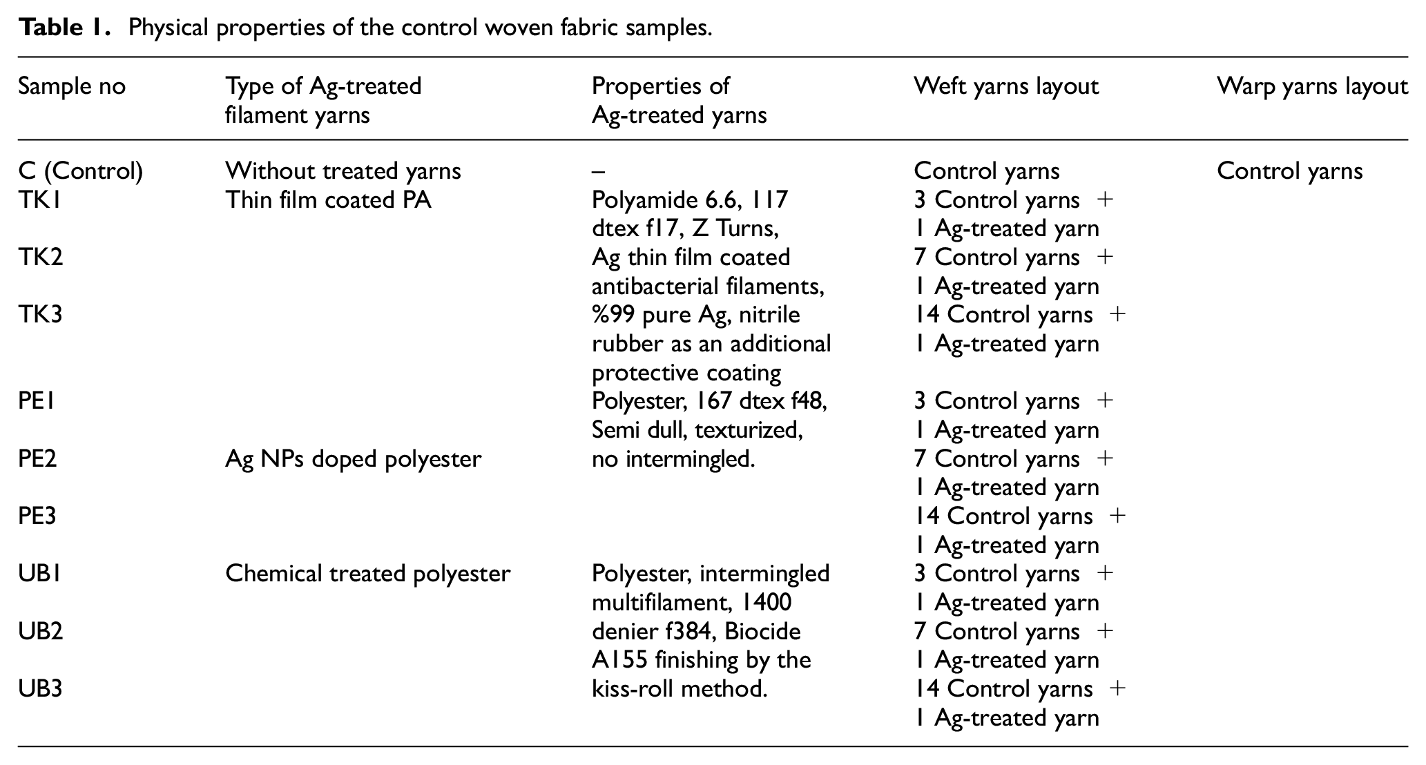
All the fabric samples are woven under industrial conditions. The structural and production parameters of the control fabric sample are presented with the general views of the finished woven fabric samples in Figure 1. The treated multifilament yarns that are polyamide (PA) thin film coated, NPs doped, and chemically finished, are provided by the Teksel Textile Products Marketing Industry and Trade Inc., the Polyteks R&D Center, the Ulusoy Textile Industry and Trade Inc., respectively. This particular type of control fabric was selected for the study due to its commercial availability and suitability for industrial conditions. The main properties of the Ag-contained yarns are given in Table 1.
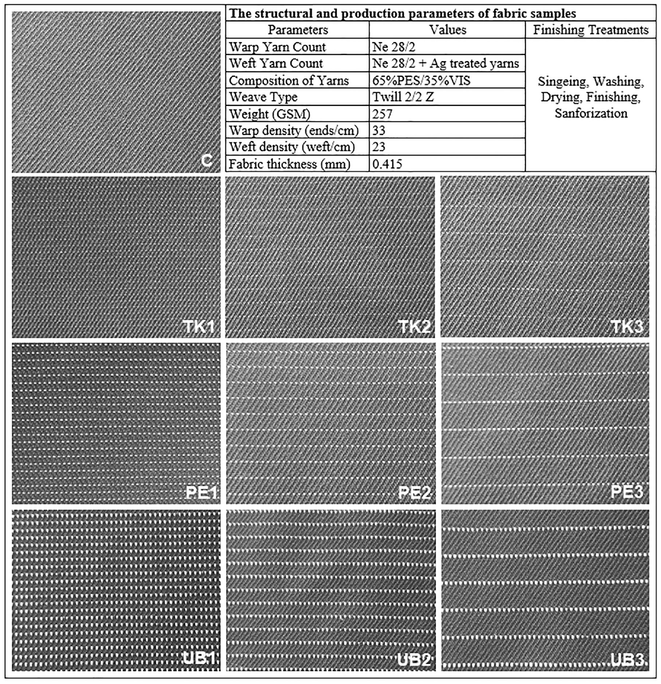
General views of the woven fabric samples.
Physical properties of the control woven fabric samples.
Applied Structural Analysis and Physical Tests
The applied structural analysis and physical tests are linear density (TS 244 EN ISO 2060), scanning electron microscopy with energy-dispersive X-ray spectroscopy (SEM-EDS), tensile for the yarns (TS 245 EN ISO 2062) and abrasion resistance (TSE EN 12947-3), pilling (TS EN ISO 12945-2), strength (TS EN ISO 13934-1), tearing (TS EN ISO 13937-1), and stiffness (ASTM D 4032-94) for the fabric samples. All the tests were carried out in accordance with the related standards.
EMI Shielding Effectiveness Measurement
The EMI shielding measurements were conducted using an Agilent PNA-L VN model network analyzer through the free space method in the 3–43 GHz frequency range. In the measurement setup, the distance between two antennas (2R) was fixed at 32 cm. The EMSE values used for normalization were calculated based on the difference in the transmission parameters (S12) obtained with and without the fabric sample. The device was calibrated at each step using the free space measurement.
EMSE is a logarithmic form of the ratio between the field or power intensity with and without shielding material. So, it was calculated as dB by using equation (1), where E is the electric field intensity; H is the magnetic field intensity; P is the power intensity; the “0” subscript represents the measurement without the sample; and the “T” subscript represents the measurement with the sample: 47
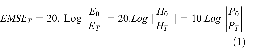
In all the measurements, if the Ag-contained threads are in the horizontal position, it is defined as the x position, and if it is in the vertical position, it is defined as the y position.
Antibacterial Activity Measurement
The AATCC 100 procedure was employed as a quantitative method to assess the fabric samples’ antibacterial activity level. Escherichia coli bacteria, known to cause various human diseases, were chosen as the test microorganism to investigate the antibacterial activity. The details of the experimental process are explained in Figure 2.

Steps of AATCC 100 procedure. 48
Surface Conductivity Measurement
The surface resistivity of the fabric samples was measured to indicate their surface conductivity. The measurements were conducted using an ELME MULTIMEG surface resistance measuring instrument under controlled conditions of 52% relative humidity and a temperature of 26°C.
Washing Test
The washing durability of the fabric samples was tested according to the TS EN ISO 105-C06 standard test method, and the washing conditions were chosen to match No. A1S washing type of the standard (five washing cycles). So, it simulated the domestic washing and thermomechanical effect. Three test samples for each fabric were prepared with a 40 × 100 mm size. Prior to the washing process, unwanted particles on the samples were removed with a vacuum cleaner.
The washing process was carried out with a 16-tube, double chamber “James H. Heal Gyrowash” washing machine. During the test, the test sample, 150 mL of grade 3 water, and 10 steel balls were added to the washing tube. The washing temperature was set as 40°C, and the duration was set as 30 min. After washing, fabric samples were dried in a drying oven at a temperature that did not exceed 60°C. To determine the effect of repeated washing on EMI shielding and antibacterial activity, the same process was repeated five times. 49
Result and Discussion
The study contains some limitations in order to obtain general judgments. The experimental design was applied to only one type of fabric. In order to obtain generalized results and optimization, it is recommended to repeat the study with different fabric types having different properties such as weight, weave, and fiber type. The Ag-treated yarns were used only in weft for cost-effectiveness. However, further optimization and efficiency can be achieved by using different placements of the Ag-treated yarns.
Analysis of Physical Properties of the Treated Yarns and Fabrics
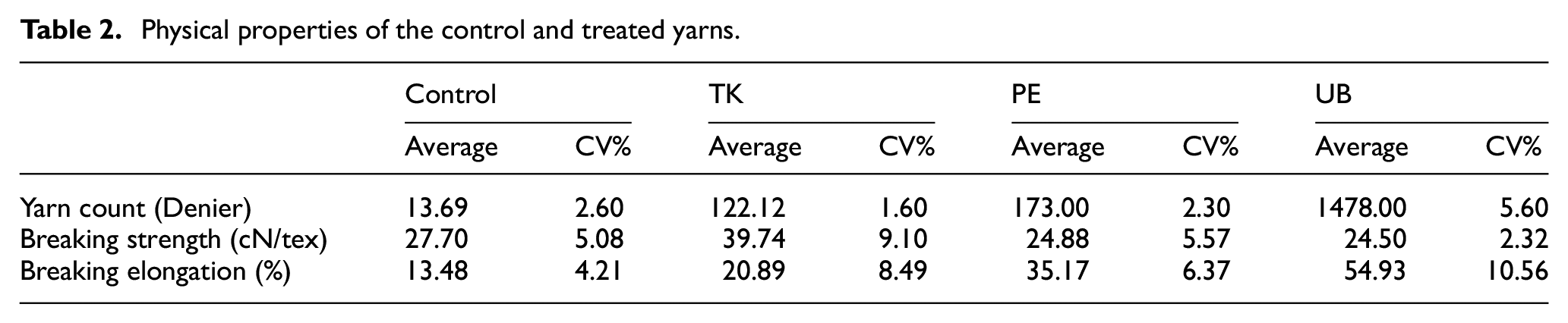
The physical properties of treated and control yarns and fabric samples are presented in Tables 2 and 3. The TK-coded yarn has significantly higher strength than others, which cannot be explained by linear density and number of filaments alone. It is suggested that the thin film coating on the filaments with a higher Ag ratio could be the reason for the higher strength and lower elongation value of TK-coded yarn. These findings show the potential of using thin film coatings to improve the mechanical properties of textiles.
Physical properties of the control and treated yarns.
Physical properties of the fabric samples.
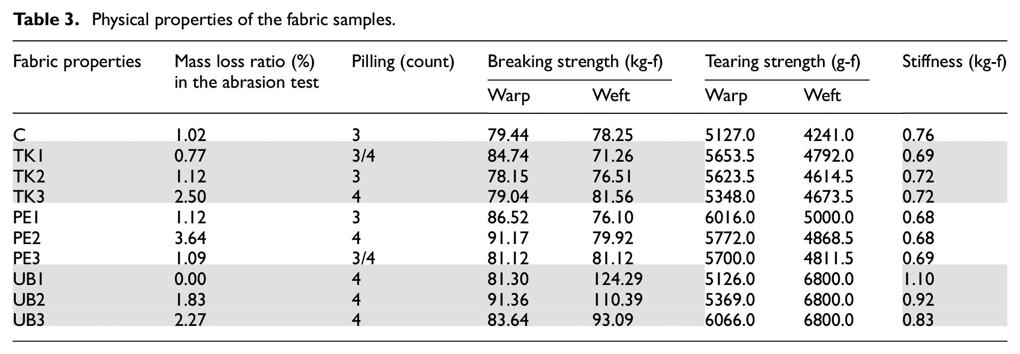
When examining the test results of the fabric samples presented in Table 3, it is observed that the abrasion resistance values of the TK and UB-coded fabrics show a significant decrease as the proportion of Ag-treated yarns increases, whereas this effect is not observed in the case of PE-coded fabric. This situation may have arisen as a result of the coating on the surface of TK and UB-coded yarns being exposed to abrasion, leading to the removal of more mass. However, the treated yarn ratio does not significantly affect the pilling property of the fabric samples.
Inserting the treated yarns into the fabrics has a negative effect on the breaking strength of TK and PE-coded samples but a positive effect on UB-coded samples in the weft direction. However, no obvious tendency of breaking strength change in the warp direction is observed for all the samples. In the literature, it is found that fabric strength in warp-wise is influenced by the warp yarn strength (31.55 %) and density (23.77 %), yarn count, raw material, weave structure, and other setting parameters.50–52 Therefore, the findings can be explained by the smaller diameter of TK and PE-coded yarns and the larger diameter of UB-coded yarns. The large contact area that arises from coarser yarns improves the frictional forces between both yarn sets, which can reduce fiber slippage during yarn failure. Thus, loaded yarns were able to withstand higher tensile force.
The proportion of Ag-treated yarns has a significant effect on the tear strength of all fabric samples, resulting in average increases of 8.1%, 13.7%, and 7.7% in the weft direction, and 10.7%, 15.4%, and 60.3% in the warp direction for TK, PE, and UB-coded samples, respectively. Although the proportion of Ag-treated yarns slightly decreases the stiffness of TK and PE-coded samples, it significantly increases the stiffness of UB-coded samples.
The treated yarn density in the fabric samples and the mass ratios of the treated yarns in the samples were measured, and then the mass ratios of Ag in fabric samples (%) were calculated in weight. It was found that the mass ratios of Ag in fabric samples (%) of TK1, TK2, and TK3-coded samples are 1.086%, 0.496%, and 0.250%, respectively. However, the other samples’ values vary in the range of 0.005–0.019%. The distances between the treated yarns are 2, 3.5, and 7 mm for TK1, TK2, and TK3-coded samples, respectively. In addition, the densities of the treated yarns (ends/5 cm) are 27, 14, and 8 for TK1, TK2, and TK3-coded samples, respectively.
SEM-EDS Analysis
SEM-EDS analyses were conducted to investigate the surface morphology of Ag-treated yarns and gather elemental analysis data. The FEI Quanta 650 Field Emission instrument was employed for SEM-EDS analyses. Figure 3 depicts SEM images of three different yarn samples (TK, thin film coated; PE, NPs doped; UB, chemically finished) at magnifications of 10,000 and 40,000.
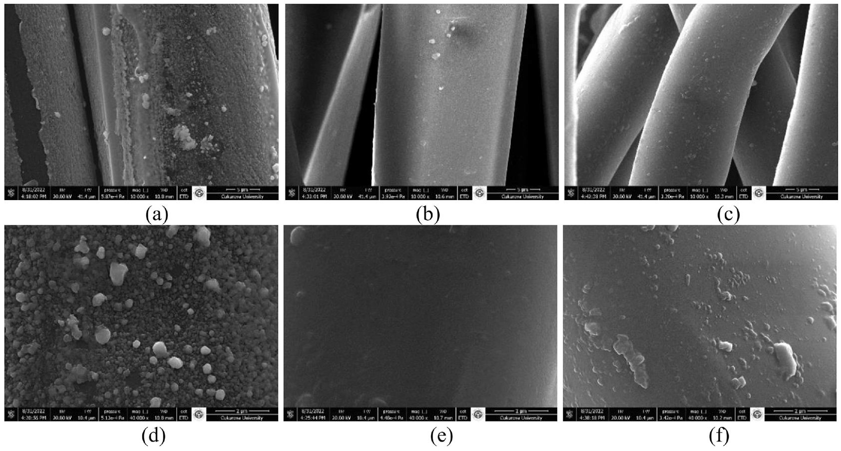
SEM images (×10,000) and (×40.000) of (a,d) TK, (b,e), PE, and (c,f) UB-coded treated yarns.
The SEM images of the TK-coded yarn sample reveal a remarkably smooth Ag layer on the yarn’s surface, which is more prominent due to the thin film coating method. The nanoparticle sizes coated on the surface of this yarn sample vary in the range of approximately 47–128 nm. In contrast, since the PE-coded yarn sample is doped with AgNPs, very few AgNP signs are observed on the surface. However, in the UB-coded yarn sample, more AgNPs and chemical substance residues are detected on the fiber surface due to chemical finishing. The nanoparticle sizes on the yarn surface range from approximately 54 to 130 nm.
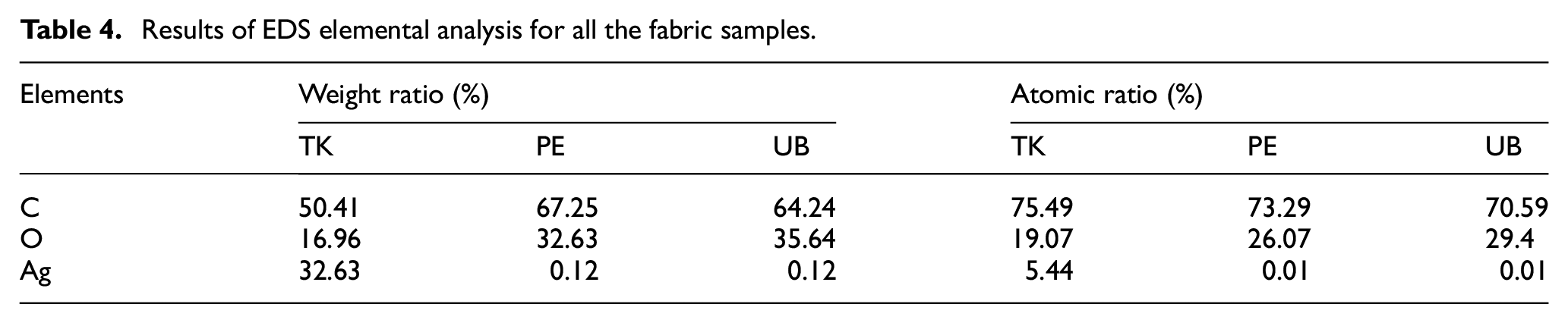
Table 4 displays the outcomes of the EDS analysis that was performed on the treated yarn samples. The obtained data demonstrate that the TK-coded yarn possesses a considerably greater amount of AgNPs (32.63% by weight) than the other yarn samples. Notably, the PE and UB-coded yarn samples exhibit a similar and low level of AgNPs (0.12% by weight).
Results of EDS elemental analysis for all the fabric samples.
Surface Conductivity of the Fabric Samples
The surface conductivity of the fabric samples is a crucial factor in developing EMI shielding materials. The surface conductivity measurements were performed on all the fabric samples for the weft-wise and warp-wise directions and 45° inclined. The results indicate that the TK and UB-coded samples exhibit an increase in surface conductivity by approximately 10 times compared to the control fabric in the 45° measurement direction but not for the PE-coded samples. Similar results were obtained in the warp direction. In contrast, the surface conductivity of the TK-coded samples shows an increase of approximately 100 times compared to the control fabric in the weft direction, while there is no significant change in the PE and UB-coded samples. These results highlight the significant impact of the fabrication method and the type of antibacterial agent used on the surface conductivity of the fabric samples. Finally, all the samples are in the antistatic (ESD) range of Electrically Conductive Spectrum (101 to 1012 Ohm/sq). Previous research has indicated that materials with surface resistivity values within the 10−2 to 101 Ohm/sq range are more suitable for electromagnetic shielding purposes. 53 The TK-coded fabric sample is the closest to this range among all the samples tested in this study. This finding is consistent with previous research and suggests that the TK-coded fabric can be used in applications where effective electromagnetic shielding is required.
Analysis of Electromagnetic SE Performance
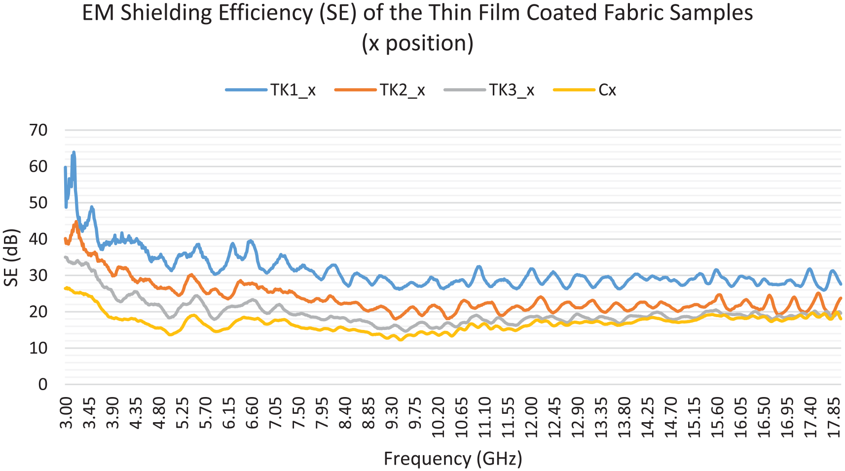
The present study involved conducting EMI shielding measurements on fabric samples at both the x (horizontal) and y (vertical) positions to assess the impact of positioning on EMSE. Moreover, samples that exhibited notable EMI shielding performance were subjected to additional measurements by being layered in different sequences to obtain insights into developing fabrics with enhanced EMSE. The EMI shielding measurement results of the TK-coded fabric samples at the x position within the 3–18 GHz and 18–43 GHz ranges are presented in Figures 4 and 5. As shown in Figure 4, all TK-coded fabric samples demonstrated significantly higher SE values than the control and other samples at the x position. This outcome can be attributed to the positive impact of the increase in the ratio of Ag content in the treated yarns and in the fabric samples. Despite this favorable difference declining up to 10 GHz, it remained significantly higher than the control sample and demonstrated stability. Notably, the SE values of TK1_x continued to be higher than 30 dB in the 3–7.85 GHz range and subsequently stabilized at the same level. The difference between TK1_x and the control sample fluctuated between 38.6 and 6.51 dB; as the frequency increases, the aforementioned difference tends to decrease. The findings highlight that the TK1_x sample exhibited the highest SE and possesses practical potential as an EMI shielding material.
EM shielding efficiency of the Ag thin film coated fabric samples (3–18 GHz).
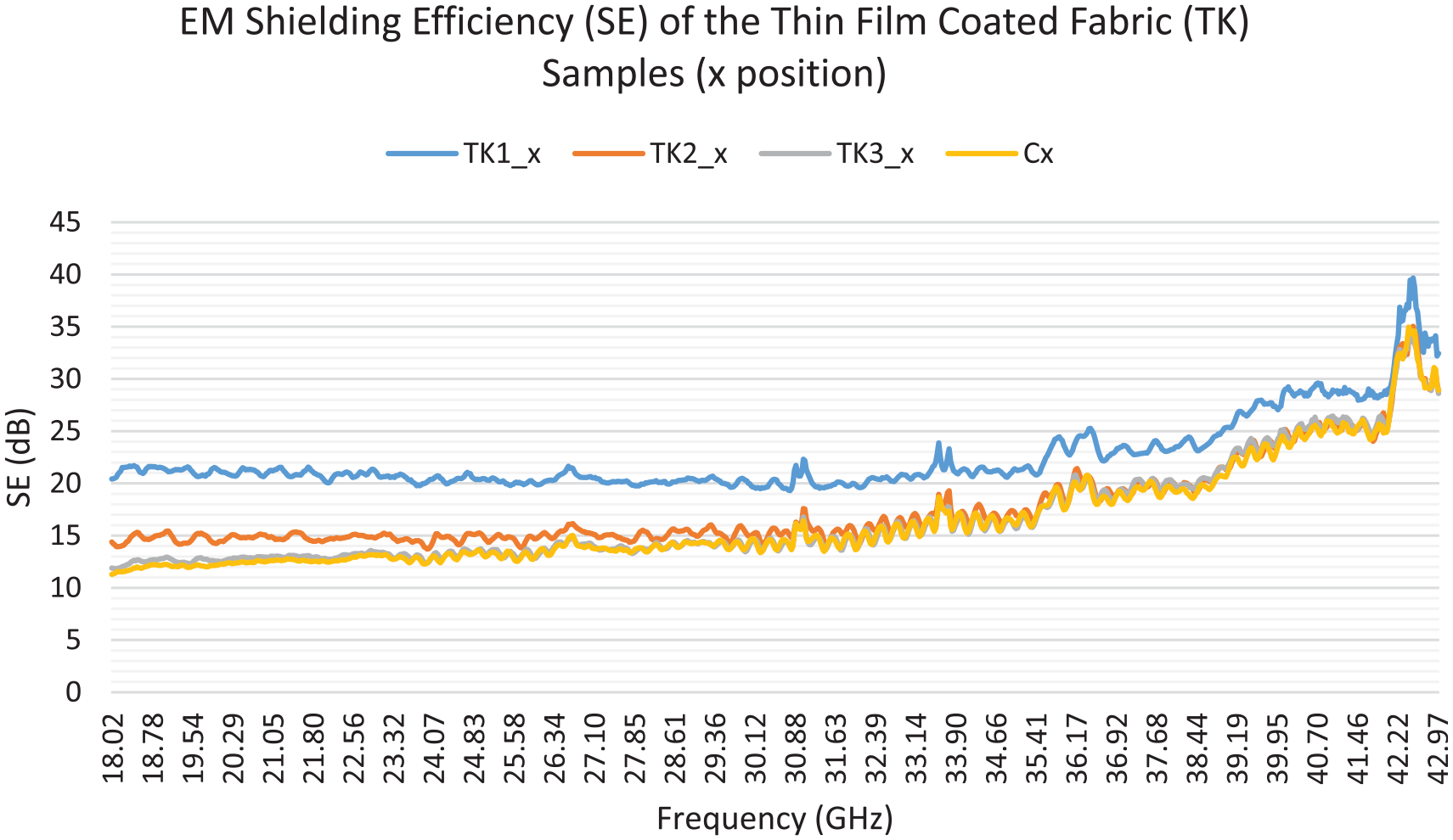
EM shielding efficiency of Ag thin film coated fabric samples in the 18–43 GHz frequency range.
The TK1_x coded fabric sample, which has the highest frequency of Ag-containing yarns, showed the highest performance in both figures. However, the efficiency of the sample remained relatively stable up to ∼30 GHz and then started to decrease with a positive acceleration, reducing the positive difference. The other two fabric samples (TK2_x and TK3_x), which exhibit significant differences in SE values in the 3–18 GHz range compared to the control fabric, continued the same trend with a negative acceleration in the 18–30 GHz range. After 30 GHz, these two samples exhibit SE values close to the control fabric, unlike the TK1_x coded sample. It is believed that the specific structure of the control fabric is responsible for the increase in SE values in all samples after 30 GHz. While only the TK1_x sample maintained the difference in SE values compared to the control fabric in the 30–42 GHz range, the other samples could not maintain this difference. After 42 GHz, the TK1_x sample also lost its SE difference. The metallized composite fabric samples generally exhibited higher SE performance in the 3–18 GHz range compared to 18–43 GHz.
However, the y-position measurements revealed that all the fabric samples did not exhibit any significant difference in shielding efficiency compared to the control fabric. Therefore, it can be inferred that the position of the fabric during EMI shielding measurement plays a crucial role in determining the SE value. Previous studies11,47 have suggested that this phenomenon is related to the direction (polarization) of the incident wave. When the conductive yarns in the metal composite fabric are aligned with the incoming wave, the EMSE becomes apparent due to the parallel polarization of EM waves. The findings of this study are consistent with the information available in the literature. In conclusion, it is recommended to consider the compatibility between the placement of conductive threads in the fabric and the direction of EM waves while designing a position-independent electromagnetic shielding material.
Figure 6 depicts the EMI SE of the fabric samples containing chemically treated UB-coded yarns. The graph illustrates that only the UB1_x coded fabric sample exhibits superior EM shielding performance, with a significant difference compared to the control fabric in the 18–39 GHz frequency range. In contrast, the other UB-coded fabric samples did not demonstrate a remarkable difference in SE values compared to the control fabric. Furthermore, the SE values of all the UB-coded fabric samples were found to be similar to those of the control fabric in the 3–18 GHz range.
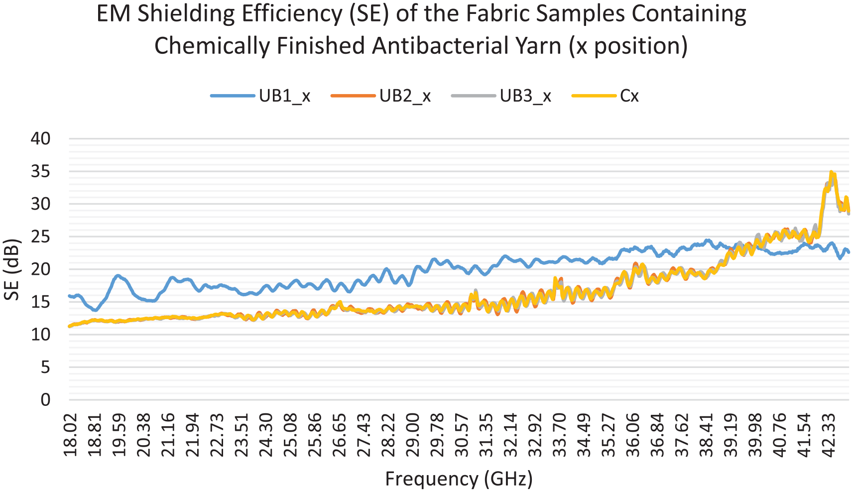
EM shielding efficiency of the fabric samples containing chemically treated yarns (18–43 GHz).
At higher frequencies (18–43 GHz), the structural properties of a material become more critical as the wavelength of electromagnetic waves becomes shorter. Therefore, fabrics with specific structural properties, such as the UB1_x coded fabric sample, may exhibit higher EM shielding performance in this frequency range. On the other hand, at frequencies between 3 and 18 GHz, the structural properties of the fabric are less influential due to longer wavelengths, and as a result, no significant difference was observed between the fabric samples. In addition, the EM shielding performance of a particular fabric sample at a specific frequency range can vary depending on the materials’ type, structure, size, and other factors.
The EMI shielding measurements conducted after the five washing cycles revealed that all the TK-coded samples exhibited enduring shielding effectiveness across all frequencies. The washing test did not exert a significant impact on the EMI shielding performance of these samples. This outcome is likely attributable to the protective polymer coating applied to the TK-coded sample fibers. However, it is noteworthy that the washing test did lead to a slight decrease in the EMI shielding performance of the UB1_x coded sample, specifically within the frequency range of 18–43 GHz. This decline may be attributed to physical and chemical damage inflicted on the coating during the washing as a result of the finishing process on the fibers.
Multilayer Fabric SE Measurement Analysis
The EMI shielding measurements have also been carried out on multilayer fabrics in different layouts such as TK1x-2x-3x or TK1x-2x. Table 5 displays the various layouts of the multilayer fabric samples used during the EMI shielding measurements.
Layouts of multilayer fabric samples during EMI shielding measurements.
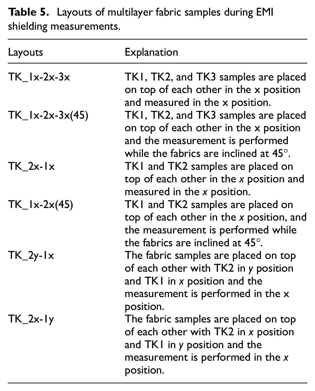
According to the results of the multilayer EMI shielding measurements of the TK-coded fabric samples, which exhibited promising results in the previous measurements, all fabric samples exhibited better SE than the control fabric with varying rates in the range of 3–18 GHz. Specifically, the fabric samples coded as TK_1x-2x-3x and TK_2x-1x demonstrated a higher SE of more than 30 dB at all frequencies in the 3-18 GHz range. The TK_1x-2x-3x sample exhibited the best performance up to approximately 10 GHz and then maintained the same level of performance efficiency as the TK_2x-1x sample. Overall, these two fabric samples substantially improved performance compared to the other samples and the control fabric. The enhanced SE performance of the TK_1x-2x-3x and TK_2X-1x samples can be attributed to the increased parallel polarization with EM waves during the multilayer layout measurements at the x position.
In the range of 18–43 GHz, all multilayer fabrics exhibit significantly better performance than the control fabric except for the TK_2x-1y coded sample. The ineffectiveness of the TK_2x-1y coded sample can be attributed to the fact that the TK2_x coded fabric sample did not show any effectiveness in Figure 5, and the TK1_y coded fabric does not have parallel polarization with EM waves. The TK_1x-2x-3x and TK_2x-1x coded samples, which showed the best performance in the 3–18 GHz range, do not maintain the same performance level in the 18–43 GHz range. After approximately 37 GHz, the TK_1x-2x-3x(45) coded sample demonstrates the best performance and continues to increase in parallel with all other samples. The increase in performance at the end of the graph may be related to the specific structure of the control fabric. Overall, it is observed that three-layer fabric layouts provide the best performance in the 18–43 GHz range.
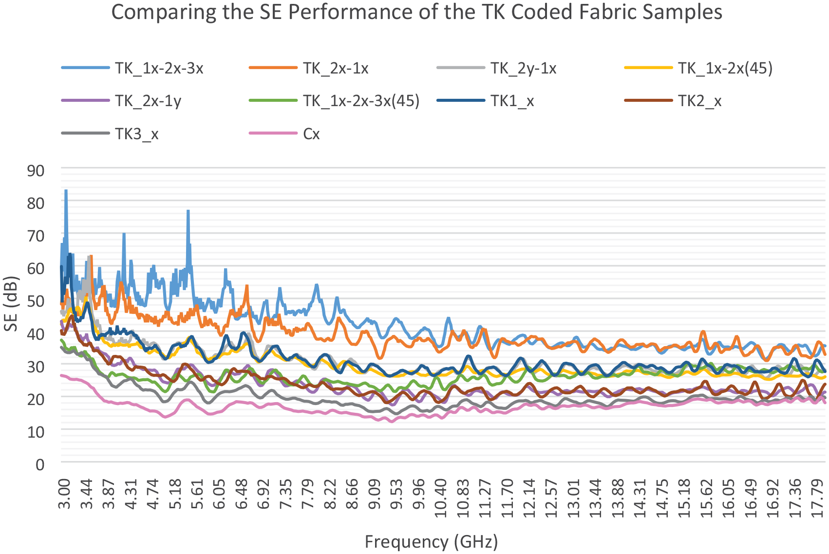
Figures 7 and 8 compare the EM shielding performance of all the TK-coded fabric samples containing Ag thin film-coated treated yarns. In Figure 7, it can be observed that the TK1_x coded sample, which had the highest density of treated yarns, provided the highest efficiency in the single-layer group (Figures 4 and 5) but showed lower performance than the TK_1x-2x-3x and TK_2x-1x coded samples in the 3-18 GHz range. Only the TK_1x-2x-3x and TK_2x-1x coded samples exhibit consistent SE performance above 30 dB in this graph. The increased performance of TK_1x-2x-3x and TK_2x-1x coded samples can be attributed to the 3D placement of treated yarns in multilayer fabrics, higher treated yarn density, and the consequent increased parallel polarization of EM waves.
Comparing the shielding efficiency of all the TK-coded samples (3–18 GHz).
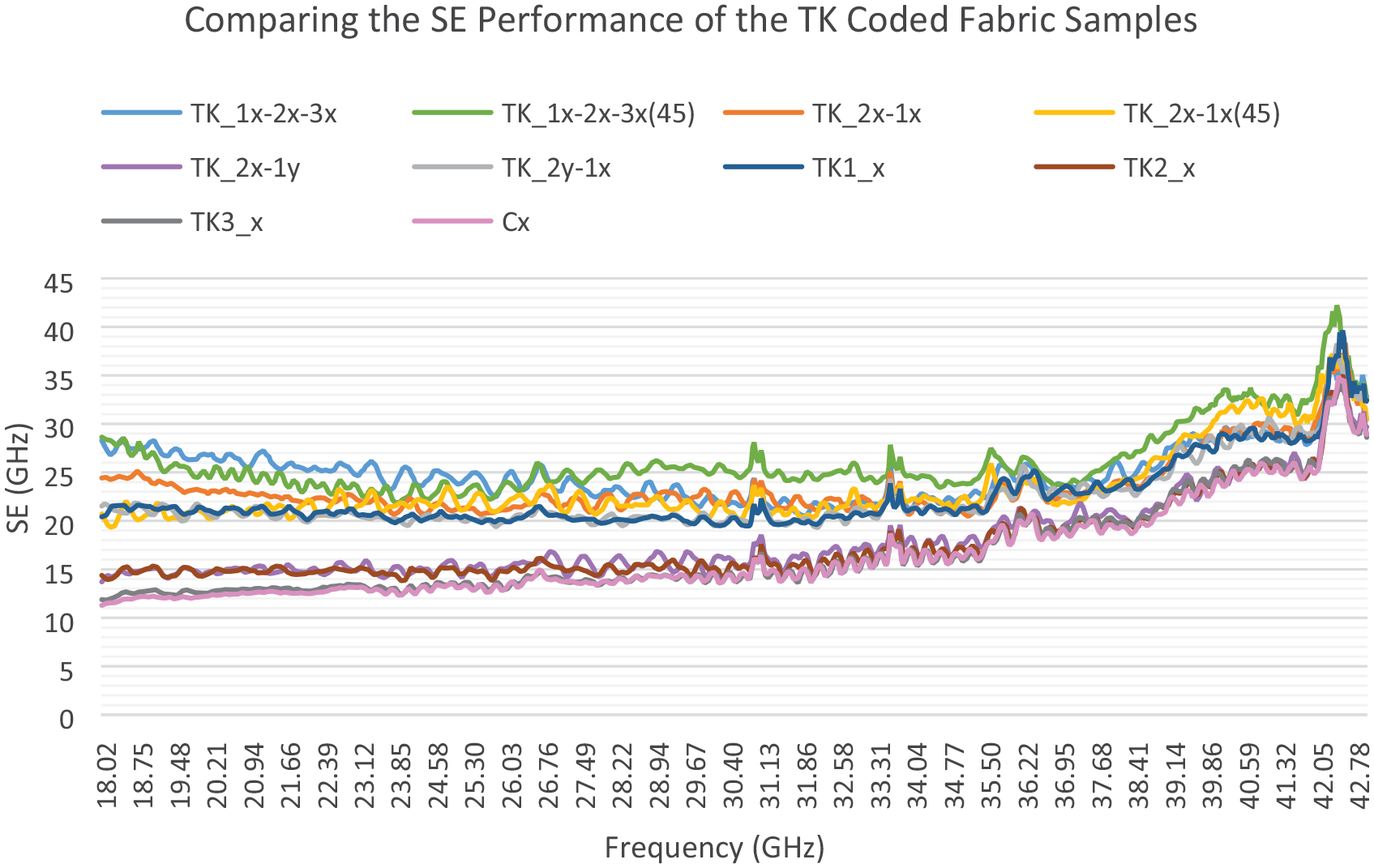
Comparing the shielding efficiency of all the TK-coded samples (18–43 GHz).
Figure 8 reveals that the TK_1x-2x-3x and TK_1x-2x-3x(45) coded samples exhibit the highest SE in the 18–26 GHz and 26–43 GHz range, respectively. Generally, the metallized fabric samples, except for the TK_3x, TK_2x, and TK_2x-1y coded samples, exhibited significantly higher shielding effectiveness performance than the control fabric. It is observed that the multilayer group outperformed the single-ply group, as depicted in Figure 7. Specifically, in the graph, all samples showed shielding effectiveness performance below 30 dB up to ∼42 GHz, beyond which the SE values increased, but the performance difference decreased relative to the control fabric in the 15–43 GHz range.
In conclusion, the results suggest that fabric samples with Ag thin film-coated yarns in the weft exhibit superior EM shielding performance compared to the other methods evaluated in this study. This could be attributed to the higher Ag ratio in the TK-coded yarns and the uniform coating of a larger fiber surface area through the thin-film coating process. Conversely, the lower AgNP ratios and non-uniform coating layer observed in the PE and UB-coded samples may be the reason for their poor SE performance. To improve the performance of NPs-doped yarns, it is recommended to increase the AgNPs ratio, and density, and improve their distribution in the yarn, while also experimenting with different NP shapes. In addition, chemically finished yarns can benefit from increasing the AgNPs ratio and coating quality to achieve higher uniformity. When designing EMI shielding fabrics with conductive yarns, it is advised to place the conductive yarns in a 3D arrangement to enhance parallel polarization with EM waves.
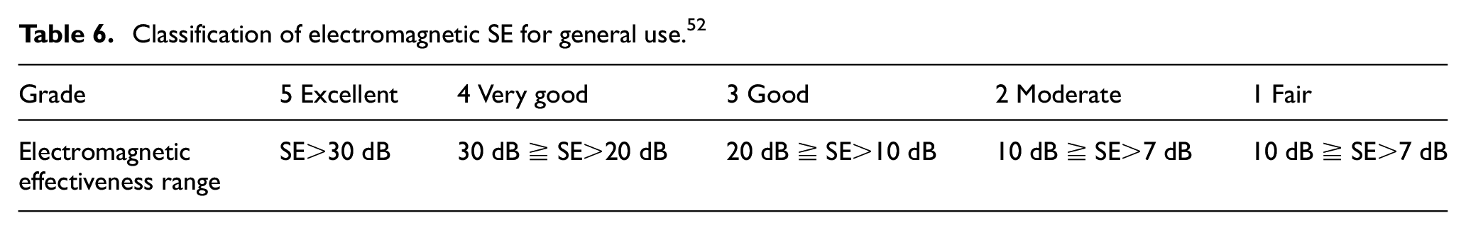
The Taiwan Textile Research Institute has categorized EMSE values into two classes: professional (Class I) and general (Class II) uses. 54 General use (as outlined in Table 6) encompasses applications such as casual wear, office uniforms, maternity clothing, aprons, consumer electronic products, communication-related products, or other novel applications. The study’s findings indicate that TK_1x-2x-3x and TK_2x-1x coded samples can be classified as “excellent” (>30 dB) for general use. In addition, all the other samples, except for T_3x coded samples, fall into the “very good” category (30 dB ≧ SE > 20 dB) within the 3–18 GHz range, which is commonly encountered in practical applications. However, in the 18–43 GHz range, all samples, except for TK_2x, TK_2x-1y, and TK_3x coded samples, can still be categorized as “very good” (30 dB ≧ SE > 20 dB) for general use.
Classification of electromagnetic SE for general use. 52
Analysis of Antibacterial Activity
The study conducted antibacterial activity tests on the fabric samples, and the results are reported in Table 7, where values of 50% and above have been emphasized in bold. It is observed that TK2, PE1, UB2, and UB3 samples exhibit bacteriostatic activities. Among the samples, TK1, TK3, and UB1 exhibit remarkable antibacterial activities against E. coli bacteria. It is found that the chemically Ag-treated PES yarn (UB1) with the highest density of treated yarns shows the best antibacterial activity. The thin film-coated polyamide antibacterial yarns (TK1 and TK3) perform second-level antibacterial activity. On the other hand, the NP-doped antibacterial yarn (PE1) exhibited only bacteriostatic antibacterial activity and not the other two samples (PE2 and PE3). It is suggested that this finding is due to the sparse distribution of AgNPs on the fiber surface and the NPs in the inner regions not showing any effect, as Gao et al. (2019) reported.
Antibacterial (AB) activities of the samples against E. coli.
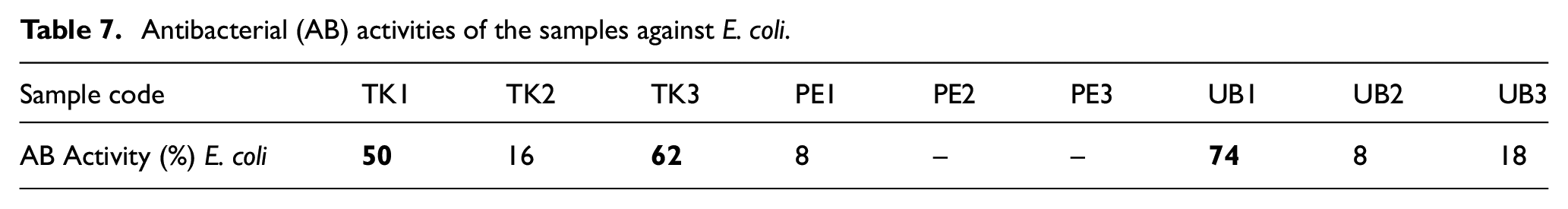
After the fifth washing cycle, the antibacterial activity of fabric samples coded TK1 (52%), TK3 (57%), and UB1 (75%) did not change significantly against E. coli. The test results have indicated a deviation of approximately 1–5% in antibacterial activity after washings. Due to the inherent nature of the test, these deviations are considered acceptable. This outcome supports that the five washing cycles did not exert a significant impact on antibacterial activity. The chosen A1S type washing standard represents the mildest procedure. Different washing conditions may have varying effects on antibacterial activity. This could be a noteworthy research topic for future studies.
In addition to increasing the AgNPs ratio and optimizing their distribution in the yarn, other parameters, such as the shape of the NPs and the type of fiber used, could also be investigated to enhance the antibacterial activity of the yarn further. Moreover, the underlying mechanisms behind the antibacterial activity of AgNPs on fiber surfaces could be explored through more advanced analytical techniques. Overall, the findings suggest that incorporating AgNPs onto the fiber surface through a thin-film coating method or chemical finishing can significantly improve antibacterial activity.
Conclusion
In conclusion, the present study investigated the performance of conductive and antibacterial yarns for EMI shielding and antibacterial applications. Physical tests indicated that thin film coating increases the strength and decreases the elongation for TK-coded yarn but this does not increase the fabric strength. The results showed that the Ag thin film-coated yarns exhibited the highest EMI shielding performance (up to 64 dB), with the highest density of treated yarns showing the best results. The multilayer fabric samples performed better than the single-layer group. The maximum EMI shielding performance of multilayer fabric samples has reached up to 83 dB. The 3D placement of treated yarns in multilayer fabrics increased the parallel polarization of EM waves, resulting in higher EMI SE. The lower AgNP ratios and a non-uniform coating layer on the fiber/yarn surface can lead to a reduced EMI performance.
Regarding antibacterial activity, the chemically finished AB yarns showed better results (74%) than the NP-doped yarns against E. coli. The antibacterial finished PES yarn with the highest density of treated yarns showed the best antibacterial activity, while the thin film-coated polyamide antibacterial yarns exhibited a second-level antibacterial performance. It was observed that AgNPs on the outer surface of the yarn are more effective in increasing the antibacterial activity of the yarn. In addition, it was determined that subjecting the fabric samples to five washing cycles did not result in a substantial alteration in their antibacterial activity and EMI shielding performance.
Overall, the study provides valuable insights into the design of conductive and antibacterial fabrics for practical applications. The findings suggest that the Ag thin film-coated yarns with high density and 3D placement in multilayer fabrics can be an effective approach for EMI shielding. In contrast, chemically treated yarns with AgNPs on the outer surface are more effective for designing antibacterial fabrics. The study also highlights the importance of optimizing the ratio and distribution of AgNPs in the design of conductive and antibacterial yarns.
Footnotes
Acknowledgements
The authors also wish to express their sincere thanks to the Polyteks R&D Center, Ulusoy, Oğuz, Matesa and Bossa Textiles Corporations for their contributions.
Declaration of conflicting interests
The author(s) declared no potential conflicts of interest with respect to the research, authorship, and/or publication of this article.
Funding
The author(s) disclosed receipt of the following financial support for the research, authorship, and/or publication of this article: This study was supported by the Research Fund of Mersin University in Turkey with Project Number 2021-1-TP2-4150.