
Abstract
Introduction
Shoulder arthroplasties have been demonstrated to provide reliable pain relief as well as functional benefits. The advent of the reverse shoulder arthroplasty allowed for expanded indications for shoulder replacement. Several studies comparing the outcomes of anatomic and reverse total shoulder arthroplasties have demonstrated decreased range of motion in the reverse arthroplasty cohort, especially in internal rotation. The authors hypothesized that slight modifications to the humeral component of a reverse shoulder arthroplasty could result in increased impingement free range of motion without significant sacrifices to stability.
Methods
A reverse shoulder arthroplasty model was fashioned to mimic a setting of anterior mechanical impingement after replacement. Sequential resections were taken from the anterior aspect of the polyethylene up to a resection of 10 mm. A solid modeling software was utilized to compare the experimental group to the control group with regard to impingement free motion. Finite element analysis was subsequently utilized to assess stability of the construct in comparison to the nonmodified polyethylene.
Results
Impingement free internal rotation increased minimally at 3 mm of resection but considerably at each further increase in resection. A resection of 10 mm resulted roughly 30% improvement in impingement free internal rotation. Instability in this model increased with modifications beyond 7 mm.
Conclusion
Slight alterations to the geometry of the humeral tray and polyethene components can result in improvements in impingement-free internal rotation without substantial increased instability in this model. Further work is needed to determine in vivo implications of modifications to the humeral tray and polyethylene.
Introduction
Although shoulder arthroplasty procedures have been performed since the late nineteenth century, the modern era of shoulder arthroplasty began with Charles Neer and his anatomic prosthesis—first described in 1953. From that time onward, shoulder arthroplasties have been demonstrated to generally provide reliable pain relief and functional benefits. 1 Two categories of shoulder arthroplasty exist—anatomic total shoulder arthroplasty (TSA) and reverse shoulder arthroplasty (RSA). The modern RSA, primarily developed by Dr Paul Grammont, was initially used for patients with rotator cuff arthropathy and is now commonly used for several additional indications.2,3
Both TSAs and RSAs can be effective treatment options for patients with various shoulder pathologies. Total shoulder arthroplasties are typically used for glenohumeral osteoarthritis with an intact rotator cuff and have been shown to significantly improve function 4 as well as significantly decrease shoulder pain. 5 Good outcomes have also been shown after RSA with many studies demonstrating low reoperation rates 6 and good long-term outcomes. 7
Achieving stability while maximizing range of motion (ROM) at the glenohumeral joint is a complex balance relating to both bony anatomy and dynamic structures. 8 Several studies comparing the outcomes of TSA and RSA have noted significant differences in postoperative ROM. Patients who underwent a RSA showed a significant decreases in internal ROM when compared to patients who underwent a TSA.9,10 The exact cause of the loss of internal ROM may be due to multiple, coincident factors but the end result is often significant difficulty as it relates to bringing the hand behind the back. The recovery of functional internal rotation after RSA is critical for many activities of daily living (ADL), primarily toileting and bathing, with upward of 20% of patients reporting difficulty with toileting 11 and others describing significant limitations in other ADL associated with internal rotation. 12
Several factors have been proposed to be the root cause of this lack of internal rotation, including positioning of the glenoid component and degree of lateralization. One study showed that the degree of inferiorization had a significant effect on internal rotation 13 while another study found that lateralization of the center of rotation resulted in ROM improvements. 14 Others have examined varying the size of the glenosphere as well as different baseplate options. 15
The advent of 3D planning software has demonstrated that most patients will eventually reach a point where further internal rotation is inhibited by mechanical impingement of the polyethylene on the glenoid. The degree to which this affects internal rotation varies widely based on the size and geometry of the native glenoid as well as the glenoid component location and size chosen. In this study, the authors have created a model resulting in early mechanical impingement. They then altered the polyethylene component to increase impingement free rotation and to assess the overall impact on stability of the components. This was done through incremental removal of the anterior aspect of the polyethylene and humeral tray. We hypothesized that an innovative geometry of the humeral component will result in less anterior impingement of prosthetics allowing for greater internal rotation with minimal loss of stability of the components.
Methods
Two separate tests were performed as it relates to the computerized experimental design. Both utilized a glenoid/glenosphere model that would result in early impingement in internal rotation which can be seen in the setting of significant anterior osteophyte formation, a large native glenoid, or a small glenosphere component. The first portion of the study was to assess improvements in impingement-free internal rotation with increasing incremental removal of the anterior aspect of the humeral polyethylene. The second portion of the study was to assess the degree to which these alterations resulted in increased instability.
Impingement Testing
The authors utilized SolidWorks, developed by Dassault Systems (Vélizy-Villacoublay). This software is a solid modeler whereby models and assemblies are created using a parametric feature-based method initially developed by PTC (Creo/Pro-Engineer). The process of creating our 3D modeled glenoid, glenosphere, and polyethylene component begins with creating a 2D sketch consisting of points, lines, arcs, conics (except the hyperbola), and splines to determine the geometry. Dimensions are added to define the size and location of features within the sketch. Relations are used to define attributes such as tangency, parallelism, perpendicularity, and concentricity. Features such as extrusions, cuts, sweeps, and fillets are utilized to create and modify the 3D model. In an assembly, mates are analogous to sketch relationships. Assembly mates define relations with respect to the individual parts or models, much like how sketch relations define conditions such as tangency, parallelism, and concentricity.
To measure the angle of impingement, the authors initially constrained the humeral tray so that it could only rotate around the local Y-axis. To do this, the authors constrained the face of the humeral bearing that would be in contact with the humeral tray and the face created from resecting the humeral bearing to be perpendicular with the XZ-plane. Next, the authors created a temporary constraint with the former face and glenoid so that their planes are parallel. Then the authors displace the humeral bearing 1 mm in the +Z direction, creating a start position consistent across all configurations. The temporary constraint was then removed (Figure 1).

Top view of the humeral bearing impinging the glenoid. The control and configurations 1 to 9 mm (increasing resection of polyethylene from left to right, continuing in second row).
To rotate the humeral bearing, the authors displaced the aforementioned face (contacting the humeral tray) 1 mm in the X-direction and 0.5 mm in the Z-direction simultaneously. This was repeated until the humeral bearing was nearly in contact with the glenoid, the displacements were then reduced to 0.2 mm and 0.1 mm, respectively, until the humeral bearing impinges the glenoid. If smaller movements were required, further reduction of the displacement values were still able to function correctly as long as the X:Z displacement ratio is 2:1. The authors then repeated this process for each configuration of the humeral bearing. Using these values, the authors were able to calculate the percent increase in the ROM of the humeral bearing as described in the results section.
Stability Testing
The finite element analysis for device stability was performed in Abaqus version 2021 (Dassault Systèmes, Vélizy-Villacoublay) using the built-in implicit dynamic solver. The implant geometry from SolidWorks was imported to Abaqus using the SAT neutral transfer format. After import, the glenoid was treated as a rigid body with a triangular surface contact element mesh of 0.3-mm average edge length, while the humeral bearing was meshed using quadratic tetrahedrons with an average edge length of 0.7 mm in the regions of anticipated contact with the glenoid (Figure 2). The surface-to-surface contact algorithm was utilized with surfaces selected based on their potential to be in contact during the simulation (Figure 2).

Finite element models of each humeral bearing configuration.
Boundary conditions were set as completely fixed on the glenoid shaft end as demonstrated in Figure 3 while the humeral bearing was fixed from rotation in all degrees of freedom. A time-dependent displacement constraint in the negative X-direction was imposed on the bearing to simulate the glenoid sliding off the bearing to determine the point of instability. Last, a constant 50N force was imposed on the bearing parallel with the glenoid shaft axis to maintain a constant normal force between simulations.

Finite element model loads and boundary conditions.
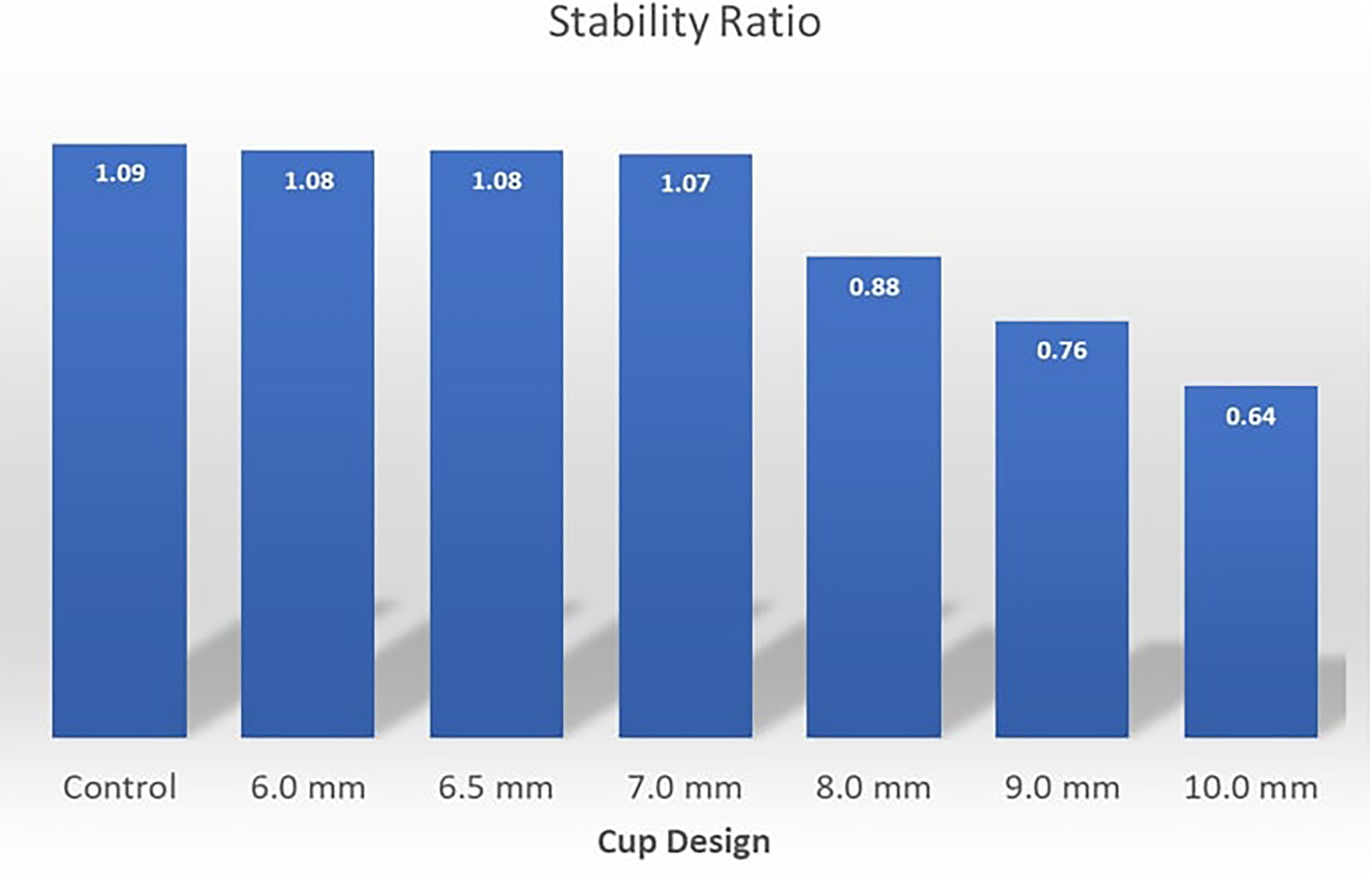
The dynamic solver settings were chosen to maintain a quasi-static environment until the moment of instability with kinetic energy monitored and verified to always be less than 0.1% of the total energy throughout the simulation. Results post-processing consisted of extracting the tangential sliding force (X-direction) versus time and subsequently converted to a stability ratio by dividing by the normal force of 50N. The ensemble of stability ratio versus time curves for all geometry cases was plotted for comparison in an X-Y chart (Figure 3).
Results
Impingement Testing
In our 3D model, resection of 2 mm or less did not result in any corresponding increases in ROM due to the resection for these configurations not effecting the point of impingement versus the control configuration. As such, the impingement angle was the same. This would vary depending on the particular geometry of the glenoid and relative position of the glenosphere but resections of this size had minimal effect in our experimental design. The table below shows the angle of impingement for each configuration along with the percent increase in relation to the control (Table 1).
Table of Angle Measurements and Percentage of Increase Compared to the Control.

Impingement free internal rotation increases minimally at 3 mm of resection but considerably at each further increase in the degree of resection. A resection of 10 mm results in just over 30% improvement in impingement free internal rotation. At this resection, impingement free motion is improved by just under 8 degrees (Figure 4).

Graph of the increased ROM% for each configuration. ROM, range of motion.
Some uncertainty exists in angle measurement as it relates to this experimental design. This arises from systemic errors of the measurements. Systemic errors are reproducible inaccuracy caused by faulty equipment, calibration, or in this case model design and limitations of software. It was found that the approximate error range is +-1.6761 degrees. This was done by repeating the measurements and then taking 3 standard deviations of the data, meaning ∼99.7% of all observations would fall within the range.
Stability Testing
The deformed state of each geometry configuration with contact pressure depicted is shown in Figure 5. This illustrates the contrast of the glenoid location relative to the edge of the humeral bearing. To better mimic what would represent an in vivo prosthesis, the cut edge was beveled slightly in those instances where the resection of the bearing surface involved a portion of the concave surface of the polyethylene (Figure 6).
Stability plotted against range of motion for each device configuration.
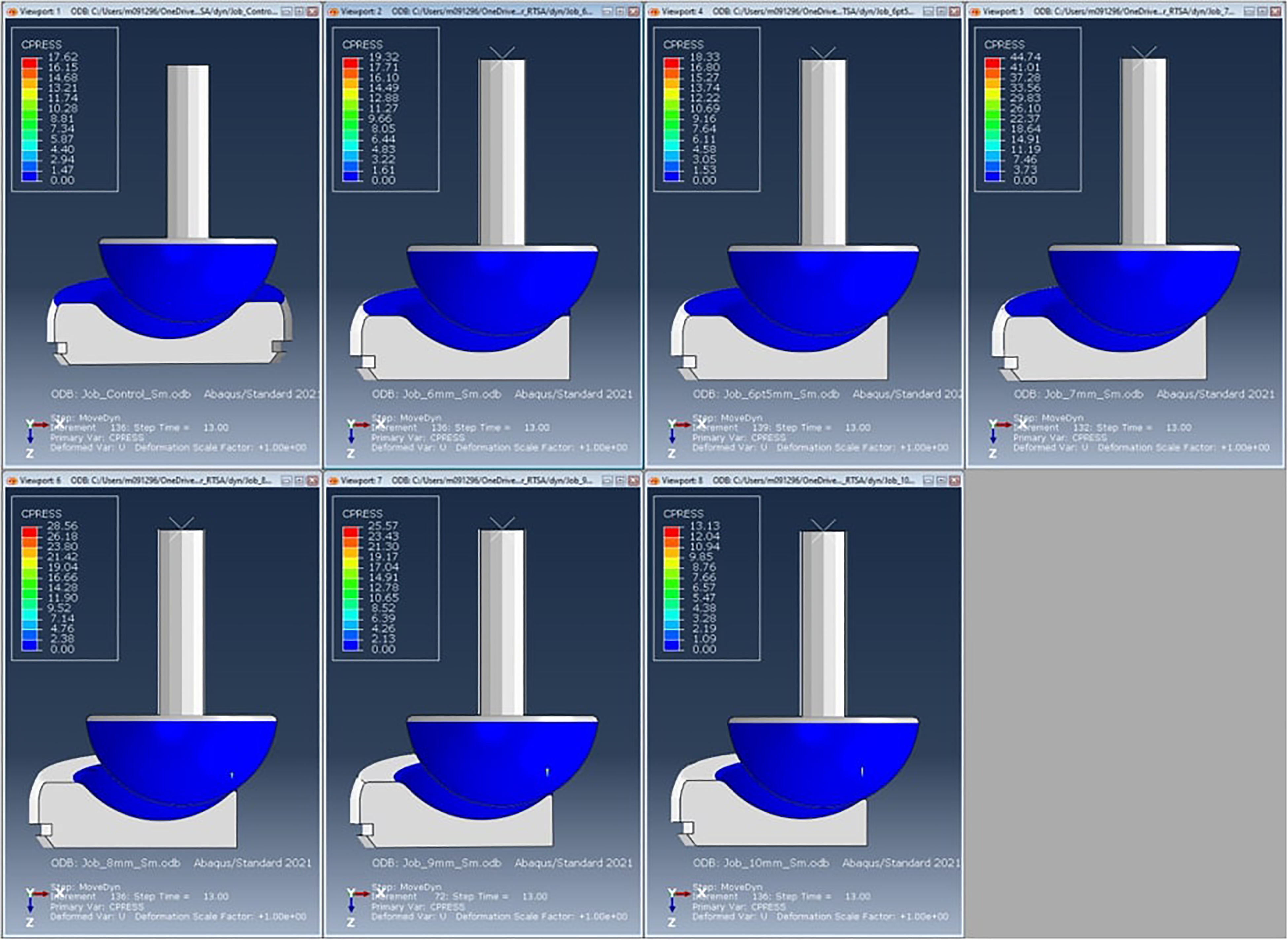
Deformed results with contact pressure at an intermediate state.
The peak stability ratio of each configuration was assessed and demonstrated a rapid decrease in stability after reaching a 7-mm cut in the humeral bearing. The differences in the stability ratio were negligible below a resection of 6 mm as resections below this amount would not violate the concave portion of the polyethylene. Removal of a small portion of the anterior polyethylene had minimal effects on overall stability in our model (Figure 5).
The stability ratio results (transverse force divided by normal force) are depicted in Figure 7. Instability in this model increases dramatically above a resection level of 7 mm, where trade-offs between increasing ROM and increasing instability become more apparent. At 8 mm of resection, the ROM is increased by 16%, while the overall stability is lessened by just over 20%. Stability trade-offs become more pronounced beyond 8 mm of resection. The cross-over point in our model is dependent on how one scales Y-axis and does not have any independent significance (Figure 7).

Stability plotted against range of motion for each device configuration.
Conclusion
Lack of internal rotation after a reverse TSA remains a major problem for patients both in terms of overall function and satisfaction after surgery. Several prior studies have attempted to determine root causes of lack of motion behind the back after a RSA. This restriction in ROM is likely multifactorial. This may be related to controllable factors such as implant placement, degree of lateralization, and humeral version, among others. Altering any one of those factors in an attempt to improve internal rotation may result in compromises in other planes of motion or may affect risks of postoperative complication including dislocation, risk of nerve injury, or risk of acromial fracture. Altering the geometry of the humeral component could increase impingement free internal rotation without altering ROM in other planes, while increasing instability of the construct.
There exists significant variability between patients with regard to glenoid shape, wear patterns, and size. In addition, significant differences exist between implant manufacturers as it relates to humeral geometry, glenosphere size, and implant design. This model was designed to evaluate one style of implant design and to simulate early anterior mechanical impingement. As such, this has all the inherent limitations of generalizability associated with choosing only one 3D model. In some cases, mechanical impingement would not seem to be a significant contributor to lack of internal rotation, especially in cases where the glenosphere size is significantly larger than the glenoid as it relates to the anterior to posterior dimension.
Modifications of the polyethylene would almost certainly affect the wear characteristics of the polyethylene itself. With moderate manufacturing processes, polyethylene wear has diminished and has become an uncommon cause of need for revision surgery. Future studies would need to look at wear characteristics of a modified polyethylene component as it relates to the longevity of the implant construct.
There may be several beneficial unintended consequences to modifying the anterior geometry of the humeral tray and polyethylene. By removing metal and polyethylene bulk in the anterior aspect of the shoulder, this would potentially allow for easier repair of the subscapularis and could improve the overall vector and mechanics of the pull of the tendon, especially in the setting of a patient with a small proximal humerus. Although not studied in this model, resecting the anterior portion of the humeral tray and polyethylene could also improve impingement free ROM with regard to forward flexion in certain patients as this represents a point of impingement in preoperative 3D modeling software.
Several criticisms could be made of this study. A cadaver model assessing stability, force characteristics, and ROM would likely be superior with regard to in vivo expectations of a modified humeral component and remains a topic for future study. This study was primarily looking at an onlay style of implant, an inlay implant would behave differently, and the benefit of removing the anterior portion of the polyethylene in an inlay style implant may be less significant. In addition, the increases in degrees of impingement free ROM were significant in terms of overall percentage of improvement but relatively modest in terms of absolute degrees of increased internal rotation in this model. That said, the difference in a patient being able to reach behind one's back for self-care, versus only to the back pocket may only require improvements in a few degrees. Further study would be needed.
This study demonstrates that relatively small modifications to the polyethylene and tray of the humeral component can increase ROM significantly with regard to internal rotation as an overall percentage compared to the status quo implant. This comes at the cost of stability, though this is relatively mild at low levels of resection. Further work is needed to determine whether this represents a viable modification of the standard geometry with regard to improving internal rotation.
Footnotes
Declaration of Conflicting Interests
The author(s) declared the following potential conflicts of interest with respect to the research, authorship, and/or publication of this article: The authors, their immediate families, and any research foundations which they are affiliated have not received any financial payments or other benefits from any commercial entity related to the subject of this article.
Funding
The author(s) received no financial support for the research, authorship, and/or publication of this article.