
Abstract
Background:
Avulsions of the biceps femoris and fibular collateral ligament (FCL) from the fibula often present as a knee ligament injury for treatment. Recent advances in suture anchors allow for knotless tension and retension of repair constructs in contrast to using transosseous sutures alone. The tensionable suture anchors may eliminate creep and improve the biomechanical performance of repairs at time point zero.
Purpose/Hypothesis:
The aim of this study is to compare the biomechanics of 2 repair constructs for biceps femoris repair. It was hypothesized that both repair constructs would effectively restore knee stability in a distal biceps femoris/FCL injury pattern, and that the modern knotless suture anchor would produce a biceps femoris repair that would fail at a higher load and exhibit greater stiffness during tensile testing.
Study Design:
Controlled laboratory study.
Methods:
Sixteen match-paired, fresh-frozen cadaveric knees (74 ± 7.5 years) were tested by external rotation (at 5 N·m) and varus (at 10 N·m) on a 6 degrees of freedom robotic system in 3 conditions: uninjured state, avulsed FCL and biceps femoris, and 1 of the 2 repair options, repair with knotless suture anchors or transosseous sutures alone. After robotic testing, repairs underwent tensile testing to failure on a uniaxial tensile testing machine to determine the failure load and stiffness of each repair construct. The mean degrees for external and varus rotation, failure load, and stiffness values were calculated for each group and compared using paired t tests between the 3 conditions and 2-sample independent t tests between the 2 repair groups.
Results:
Robotic testing of both repairs showed significant reductions (P < .05) compared with the sectioned state in varus rotations at 0° and 30° and external rotations at 0° of knee flexion. The repair with suture anchors significantly reduced laxity in varus rotation at 60° of knee flexion (P = .02), whereas the suture alone repair did not (P = .09). Tensile testing revealed mean failure loads for the knotted suture repair of 317 N (range, 193-450 N) and for the knotted anchor repair of 447 N (range, 239-818 N), showing no statistically significant difference (P = .12). The mean stiffness for the knotted suture repair was 9.45 N/mm (range, 4.6-12.8 N/mm). The anchor repair was 9.16 N/mm (range, 3.6-15.3 N/mm), showing no statistically significant difference (P = .87). The sectioned state was significantly different from the intact state at all flexion angles for all conditions tested (P < .05).
Conclusion:
Our study demonstrated that a transosseous biceps femoris repair with knotless suture anchors performed similarly to a transosseous biceps femoris repair with suture alone in robotic varus and external rotation testing. With tensile testing, a higher failure load was observed in each matched pair with suture anchor repair. However, no statistically significant differences were found between the restoration of knee kinematics, mean failure loads, and stiffness in these 2 repair constructs.
Clinical Relevance:
Understanding the biomechanical and tensile performance of the biceps femoris aids clinicians with pre- and intraoperative decisions.
The biceps femoris functions as the most powerful flexor in the leg and is a dynamic stabilizer of the posterolateral corner (PLC) in open kinetic chain activities.1,8,13,16 Previous studies have found that sectioning of the fibular collateral ligament (FCL), popliteofibular ligament, and the popliteus tendon increases primary varus and external rotation.14,18 The biceps femoris is the most commonly injured element of the distal hamstring; however, isolated distal biceps femoris injuries are rare.5,8 Imaging studies have reported that PLC injuries account for 16% of all knee ligament injuries but typically occur in combination with injury to multiple knee ligaments or tendons.10 -12 Because of the functional importance of the biceps femoris in knee flexion and stabilization, surgical repair is often considered after an acute avulsion injury. In our experience, a not uncommon injury pattern in American football is a combined anterior cruciate ligament injury with a concomitant avulsion of the biceps femoris and the FCL off the fibula as one sleeve. A consensus on optimal surgical treatment has yet to be reported. 13
Multiple repair techniques have been described in the literature for an avulsion injury of the biceps femoris from the fibula and proximal tibia. In a previous cadaveric model, repair with transosseous fibular tunnels proved superior in tensile repair strength when compared with direct repair with suture anchors placed into the fibula because of the porous nature of the proximal fibula. 2 As advances in tendon and ligament repairs and reconstructions continue, novel knotless suture anchors have recently gained popularity because of their self-locking mechanisms, soft body design, and tensionable/retensionable technology. The fixation method of soft anchors also allows them to be fixed on the cortical side of a bone with their suture mechanism pulled through a bone tunnel, as opposed to being placed within the bone, which avoids reliance on soft metaphyseal bone. This may prove especially useful around the proximal fibula. Implementing this novel technology may also enable improved restoration of biokinetics and enhanced strength/stiffness of repairs. Specifically, the ability to tension and retension may facilitate the elimination of creep in a repair construct.
This study aimed to evaluate the biomechanics of repair constructs using modern, knotless suture anchors transosseously compared with traditional transosseous tunnel constructs, utilizing robotic kinematic and tensile testing. We hypothesized that both repair constructs would effectively restore knee stability in this distal biceps femoris/FCL injury pattern. We also theorized that the novel knotless suture anchors would perform better on tensile testing than sutures and transosseous bone tunnels alone for the biceps femoris.
Methods
Eight matched-pair fresh-frozen cadaveric specimens were used to compare PLC repair constructs between the 2 groups. One group consisted of a repair of the biceps femoris to the fibula with a suture-alone, transosseous technique, which has been described in the literature. 2 The second group used transosseous tunnels and knotless, all-suture suture anchors (Knotless Knee FiberTak; Arthrex) to produce a tensioning/retensioning mechanism with the anchors.
Specimen Preparation
Each pair of knees was prescreened for bone degeneration, arthritis, previous knee surgery, and intra-articular damage. Before testing, each specimen was thawed at room temperature for 24 hours. Each knee was inspected manually for ligament laxity, stiffness, full extension, and scars indicating previous knee surgery. The research institution is approved to receive cadaveric specimens for research and training purposes and does not require institutional review board approval for cadaveric biomechanical studies.
The mean specimen age was 74 ± 7.5 years (range, 62-84 years), the mean height was 67.1 ± 3.7 inches (range, 61-72 inches), and the mean weight was 156 ± 52.5 lb (range, 100-250 lb). Five specimens were from male donors, and 3 were from female donors.
Each knee was received from an American Association of Tissue Banks–accredited tissue bank with the femur, tibia, and fibula cut at midshaft. All soft tissue was removed from the proximal end of the femur and the distal end of the tibia for an approximate length of 8 cm. For each specimen, as performed previously in cadaveric PLC studies, the fibula was fixed distally from the head to the tibia using a screw to preserve its anatomic relationship. The fibula was resected distal to the screw to better fit the tibia into its bone pot.17,18 The bone ends were fitted coaxially into tubular aluminum bone pots using woods metal and transfixed with 2 perpendicular drill bits to enhance rotational stability within the metal pots.
Operating Protocol
Biomechanical testing was performed using an industrial robot (Kuka, GmbH) with 6 degree of freedom, combined with a 6 degree of freedom force sensor (Omega160 IP65; ATI Industrial Automation; Apex). Joint kinematics and kinetics were integrated and controlled via the simVitro software package (Cleveland Clinic). This system is capable of operating under both kinematic and kinetic control, with kinematic repeatability of 0.1 mm and 0.1° and load cell sensitivity of 0.25 N. 3
The tibia and femur of each specimen were first potted and clamped for attachment to the robot. The tibia and femur were then mounted to the force sensor and the robot, respectively. Using a Micron Series Digitizing Probe (MSP0001, OptiTrack, Planar Systems), the joint coordinate system was established between the tibia and femur, and it was related to the coordinate systems of the force sensor and the robot. The loads were measured in the tibia-fixed coordinate system, and the kinematics were measured in the joint coordinate system, as described by Grood and Suntay. 7
Once the specimen was mounted to the robot, the robot's position was fine-tuned using the SimVitro software to define the neutral position of the knee. All loads were tuned to zero except for a 20 N compression force to simulate gravity and a 0.5 N·m extension torque to define 0° of flexion. This location was considered the neutral position of the knee.
The custom simVitro software was then used to optimize the manually digitized joint coordinate system for accurate simulation and measurement of knee joint movements. Once the optimized coordinate system was established, the knee was fully extended and positioned in a zero-loaded state to reestablish the neutral position.
Before robotic testing, each knee was preconditioned by cycling through varus and valgus, as well as internal and external rotational loads, 5 times to minimize soft tissue hysteresis. Each paired specimen then underwent 3 stages of testing using previously described protocols.14,18 Varus and external tibial rotation laxity of the knee were measured while applying 10 N·m of varus torque and 5 N·m of external rotatory torque at 0°, 30°, 60°, and 90° of flexion. This protocol was repeated on each specimen for the 3 stages of testing. Biomechanical stability was tested first under intact conditions of the PLC. Next, stability was measured after the distal biceps femoris and FCL were incised from their distal insertions. Specimens were then subjected to a final test after PLC complex repair. Each matched pair included 2 repair techniques, 1 specimen with the knotted suture only, and the other with the knotless suture anchor technique, with laterality randomly assigned.
Surgical Biceps Femoris and FCL Sectioning Technique
After native testing, a surgical approach to the PLC was performed. The biceps femoris was identified at its insertion upon the fibular head. A scalpel with a No. 15 blade was used to begin dissecting/peeling the distal fibular insertion of the biceps femoris off the fibula. This peeling continued with the FCL, followed by the medial and proximal insertions of the biceps femoris, until the entirety of the biceps femoris and FCL was off the fibula.
Repair Techniques
All repair constructs utilized three 2.0-mm bone tunnels. The proximal tunnel entered the anterior aspect of the fibula approximately 8 mm from the anterior/proximal aspect of the fibula and exited the posterior aspect of the fibula approximately 8 mm from the posterior tip of the styloid. The distal tunnel entered the anterior aspect of the fibula approximately 14 mm from the anterior/proximal aspect of the fibula and exited the posterior aspect of the fibula approximately 14 mm from the posterior tip of the styloid. The tunnels were drilled in a fashion to leave an approximate 4-mm bone bridge between the 2. A third 2-mm tunnel at the FCL insertion was drilled between the 2 anterior to posterior bone tunnels, from the FCL insertion horizontally to the posteromedial fibular head, aiming 2 mm posterior to the proximal tibia-fibula joint capsule.
For the suture-alone repair, two 1.3-mm flat-braided sutures (SutureTape; Arthrex) were separately passed proximally through the biceps femoris for approximately 4 passes in a running Krackow fashion and returned distally for 4 passes in the same fashion. These entered and exited the biceps femoris tendon at its posterior insertion. A third suture was used for FCL repair, entering and exiting the FCL 2 cm proximal to its distal insertion. A suture anchor was passed through the middle bone tunnel for FCL repair and incorporated in the FCL Krackow suture at the distal insertion. The Krakow suture for the FCL was run through the repair loops of the suture anchor. The repair loop's slack was removed to the aperture of the repair tunnel. The Krakow was then continued proximally and tied. Then, the biceps femoris suture tapes were passed through the proximal and distal bone tunnels using a posterior-to-anterior direction and a straight suture passing device (SutureLasso Needle; Arthrex). Using a free needle, after the biceps femoris suture tapes exited anteriorly, we passed the sutures separately through the anterior attachment of the biceps femoris. Using a locking knot, we tied each suture pair anteriorly over the bone bridge created between the tunnels. Figure 1 presents an example of the suture-alone biceps femoris repair construct.

Suture alone biceps femoris repair construct.
The biceps femoris repair with suture anchors utilized the same 3 tunnels as described in the suture alone construct. The repair started with 3 Krakow Sutures: 1 for the proximal fibular insertion of the biceps femoris, 1 for the FCL insertion, and 1 for the distal fibular insertion of the biceps femoris. The Krackow sutures were initiated and not completed, with the limbs exiting at the tendinous portion of their footprint (Figure 2).

(A) The insertional locations of the biceps femoris, FCL, and anterolateral ligament, with footprint surface area presented as the mean (range) in mm2. Reprinted with permission from Branch et al. 2 (B and C) Three Krakow sutures were initiated: 1 for the proximal fibular insertion of the biceps femoris (Red Arrow), 1 for the FCL insertion (Black Arrow), and 1 for the distal fibular insertion of the biceps femoris (Blue Arrow). The Krackow sutures are initiated and not completed, with the limbs exiting at the tendinous portion of their footprint. The double red arrows point to the fibular head. FCL, fibular collateral ligament.
Next, 3 drill tunnels were created in a specific order of steps to (1) incorporate the running sutures, (2) prevent tunnel convergence, and (3) prevent wrapping up the suture mechanisms of the suture anchors in the drill bit. The first most proximal tunnel was created, anterior to posterior, and a suture passing device (SutureLasso Needle; Arthrex) was placed through the drilled tunnel. Then, the second tunnel, beginning at the FCL footprint and running laterally to medially, was created, and the drill bit was left in place (Figure 3A). Then, the first suture anchor was shuttled into place, from anterior to posterior (Figure 3B). Then, the Krakow suture for the proximal insertion of the biceps femoris was run through the repair loops of the suture anchor (Figure 3C). The slack in the repair loop was removed. The Krakow was then continued proximally. The 2-mm drill bit was removed and replaced with the suture passing device. The third tunnel was drilled using the suture passing device, which was kept in position to protect the tunnel's integrity (Figure 3D). The remaining suture anchors were passed into position, the FCL from medial to lateral and the distal insertion of the biceps femoris from posterior to anterior. Then, the Krakow suture for the FCL was run through the repair loops of the suture anchor. The slack in the repair loop was removed. The Krakow was then continued proximally and tied. This was repeated for the repair suture and anchor for the distal insertion of the biceps femoris. All Krakow sutures were then tied. All sutures were tensioned and retensioned using the suture anchor mechanisms to eliminate creep from the construct (Figure 3, E and F).

Biceps femoris repair with suture anchors involved drilling with a 2-mm drill bit for the proximal biceps femoris first, then removing the drill bit and replacing it with a straight suture passing device. The second tunnel was drilled for the FCL with the suture passer in place to avoid tunnel convergence. (A) A suture anchor was shuttled into position for the proximal insertion of the biceps femoris. (B) The proximal biceps femoris repair suture was loaded through the loops of the first anchor. (C) Tension was removed until the repair sutures were pulled to the aperture of the tunnel. The proximal biceps femoris Krackow suture continued proximally. The final tunnel was drilled for the distal insertion of the biceps femoris. (D) The remaining anchors were passed, and the Krackow sutures configurations were completed and tied (E and F). The anchor mechanisms were used to tension and re-tension the repair. FCL, fibular collateral ligament.
Tensile Testing
Immediately after biomechanical testing of the 2 biceps femoris repairs on the Kuka robot (Figure 4A), all specimens were disarticulated and further dissected to expose the biceps femoris tendon-muscle tissue. Each specimen was tested on a uniaxial tensile testing machine (Model 68TM-5; Instron) with a 1 degree of freedom holder and a screw side-action tensile grip mount (Figure 4B). Each specimen’s biceps femoris tendon was secured with the screw side-action clamp superiorly, while the tibia bone pot was fixed inferiorly to the machine. Specimens were kept moist with saline solution after dissection and repair. The testing protocol consisted of a 5 N preload period lasting 10 seconds, a cyclic loading preconditioning period, and a load-to-failure period. Throughout testing, tensile load and displacement were recorded at 10 Hz. The preconditioning period consisted of 20 cycles, ranging from 5 to 30 N at a rate of 0.5 mm/sec, and the load-to-failure period involved increasing the force at a rate of 0.5 mm/sec until failure. The tensile pull was applied parallel to the fibula to simulate the knee in full extension. Throughout the testing process, actuator force and displacement were captured, and mechanical testing software generated a displacement curve using Bluehill 2 software (Instron). The failure load was defined as the maximum force that could be sustained before the structural integrity of the repair construct was compromised, as indicated by the highest peak on the displacement curve. Stiffness values were determined by calculating the slope of the load-displacement curve during the initial loading of the construct from 5 to 30 N. The included region was linear and sufficiently below the failure load to exclude nonlinear deformation. 2 Specimens were visually monitored for slippage within the clamp during testing and posttest analysis of the displacement curve. When slippage occurred, specimens were reloaded onto the machine, and the described testing protocol was repeated.

(A) Specimens were first tested on a 6 degree of freedom robotic system and then (B) on a uniaxial tensile testing machine.
Statistical Analysis
Eight specimens were used per group. This number was based on previous biomechanical testing studies that found this sample size sufficient for evaluating the medial and lateral knee structures.9,20 The mean and standard deviations were calculated for each test using Excel 2024 (Microsoft). Paired t tests were performed to individually compare the intact to the sectioned states and the sectioned to the repaired states. Unpaired t tests were used to directly compare the 2 repair techniques. Differences were considered significant when P < .05, and no adjustments were made for multiple comparisons.
Results
Kinematic Testing
Table 1 summarizes the results of varus testing. The sectioned state was statistically different from the intact state at all flexion angles for all conditions tested (P < .05). Both repairs were statistically different from the sectioned state at all flexion angles except 60° and 90°. At 60°, the biceps femoris repair with suture anchors was statistically different than the sectioned state, but the biceps femoris repair with suture alone was not. Neither repair was statistically different at 90°. Neither repair was able to restore the injured state to its original, uninjured state.
Results for Varus Testing for 2 Repair Methods a
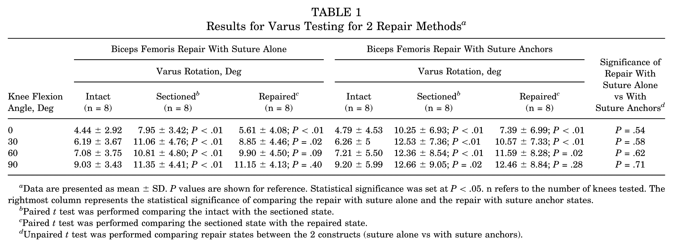
Data are presented as mean ± SD. P values are shown for reference. Statistical significance was set at P < .05. n refers to the number of knees tested. The rightmost column represents the statistical significance of comparing the repair with suture alone and the repair with suture anchor states.
Paired t test was performed comparing the intact with the sectioned state.
Paired t test was performed comparing the sectioned state with the repaired state.
Unpaired t test was performed comparing repair states between the 2 constructs (suture alone vs with suture anchors).
Table 2 summarizes the results of the external rotation testing for 2 repair techniques. The sectioned state was significantly different from the intact state at all flexion angles for all conditions tested (P < .05). The repairs performed similarly at all flexion angles. For both repairs, the repaired state was statistically different from the sectioned state only at 0° (P < .05). Neither repair restored stability equal to that of the uninjured state.
Results for External Rotation Testing for 2 Repair Methods a

Data presented as mean ± SD. P values are shown for reference. Statistical significance was set at P < .05. n refers to the number of knees tested. The rightmost column represents the statistical significance of comparing the repair with suture alone and the repair with suture anchor states.
Paired t test was performed comparing the intact with the sectioned state.
Paired t test was performed comparing the sectioned state with the repaired state.
Unpaired t test was performed comparing repair states between the 2 constructs (suture alone vs with suture anchors).
Figures 5 and 6 present box and whisker plots of the repaired state subtracted from the injured state to compare the 2 repair techniques in varus and external rotation, respectively. Greater scores indicate better restoration of the uninjured state. The 2 repair techniques did not differ significantly from each other at any flexion angle for all conditions tested (P > .05). The interquartile ranges (IQRs) were smaller in knotless suture anchor repairs compared with transosseous repairs for all flexion angles except for 0° in both varus and external rotation. During varus testing, the knotless suture anchor group had IQRs of 2.03°, 1.88°, 1.12°, and 0.86° at 0°, 30°, 60°, and 90°, respectively, and the suture-only group had IQRs of 1.91°, 3.36°, 2.42°, and 1.08°, respectively. During external rotation testing, the knotless suture anchor group had IQRs of 1.42°, 0.71°, 0.56°, and 0.89°, and the suture-only group had IQRs of 0.95°, 1.82°, 1.36°, and 1.17° during external rotation testing.

Box and whisker plots of the repaired state, subtracted from the injured state, are used to compare the 2 repair techniques in varus rotation.

Box and whisker plots of the repaired state subtracted from the injured state to compare the 2 repair techniques in external rotation.
Tensile Testing
The mean (95% CI, low-high) failure loads were as follows: biceps femoris with suture anchors, 447 N (239-818 N); and biceps femoris with suture alone, 317 N (193-450 N). Although the biceps femoris repair with suture anchors construct had a higher failure load in each matched pair, interconstruct comparison between the 2 repair groups revealed no statistical difference in mean failure load (P = .12) The mean (95% CI, low-high) stiffness values were as follows: biceps femoris with suture alone, 9.16 N/mm (3.6-15.3 N/mm); and biceps femoris with suture anchors, 9.45 N/mm (4.6-12.8 N/mm). Interconstruct comparison between the 2 repair groups revealed no statistical difference in stiffness (P = .87). Table 3 summarizes the results of the tensile testing for the 8 specimens. The mode of failure for all biceps femoris with suture anchor repair constructs was anchor pull-through. The mode of failure for all biceps femoris with suture alone constructs was suture cut through.
Tensile Testing Results for Failure Load and Stiffness for Each Specimen Matched Pair a

Failure load P = 0.12; Stiffness P = .87.
Discussion
The most important finding of this study was that biomechanically transosseous biceps femoris repair involving tensionable/retensionable suture anchors performed similarly to transosseous biceps femoris repair with suture alone. No significant difference was found when directly comparing the rotations of both repair techniques at any flexion angle for both varus and external rotation testing (P > .05). The transosseous knotted suture anchor has previously performed better than direct suture anchor techniques. 2 The previous comparison placed anchors within the bone, while this study placed the anchors on the cortical surfaces and passed the suture mechanisms through transosseous tunnels. When comparing the 2 constructs, the smaller IQRs in the biceps femoris repair with knotless suture anchors suggest, but do not prove, a more consistent construct than the repair using suture only. Specifically, the knotless suture anchor group showed smaller IQRs than the suture-only group at 30°, 60°, and 90° of flexion for both varus and external rotation testing. This supports the added value of the tension/retensionable effect of the anchors to the repair. As both constructs performed similarly, surgeon preference may be the deciding factor, as biomechanical data support both options. Despite the similar behavior between the 2 repair groups, neither technique was able to reproduce the stability of the intact state. In various knee ligament repairs and reconstructions, comparing intact and repaired states, similar results have been demonstrated in cadaveric studies.4,21
This study also evaluated the tensile strength of the 2 constructs. Although there were no significant differences between the 2 repair constructs regarding ultimate failure load (P = .12) and stiffness (P = .87), the biceps femoris repair with suture anchors demonstrated a higher mean failure load (446.67 ± 184.09 N) compared with the suture-only repair (317.22 ± 77.73 N). Additionally, the suture anchor repair had a higher failure load than the suture-only repair in each of the 8 matched pairs (Table 3). This consistent trend suggests a significant difference in failure load that may be more pronounced in a larger sample set. A previous study evaluated the tensile properties of biceps femoris repair constructs involving suture anchors placed into the fibular head and found that these constructs failed at a lower load than transosseous tunnels and sutures alone. 2 This was attributed to the porous bone of the proximal fibula being less advantageous for anchors into the fibula. 2 This study placed the soft body anchors on the cortical surface of the fibula while passing the knotless suture mechanism through a transosseous tunnel. This produced the dual advantage of a transosseous tunnel construct and the tensionable/retensionable function of the anchors. The fixation design of the soft body anchors upon the aperture of a transosseous tunnel may explain the increased load to failure observed at testing.
One limitation of this study is the time zero comparison, as no biological repair or remodeling can occur, which limits its translation to a clinical comparison. Additionally, the differences between the injured states were not equal within matched pairs, which may reflect natural variability in how each specimen responded to the same sectioning technique or variability with robotic testing. Additionally, the advanced age of the specimens, with a mean age of 74, does not accurately reflect the typically younger athletic population that is affected by this injury pattern. A final limitation is that the vector of tensile testing was in a direct axial plane when uniaxial testing was applied to the repairs. This represents full knee extension, which is the usual position of injury of the PLC.6 -8,15,19 It could be argued that repairs may fail with hamstring contraction, which would occur in greater knee flexion. 2 Finally, the sample size was selected based on precedent from similar biomechanical studies rather than a formal power analysis, which may limit the ability to detect smaller between-group differences.
Conclusion
Our study demonstrated that a transosseous biceps femoris repair with knotless suture anchors performed similarly to a transosseous biceps femoris repair with suture alone in robotic varus and external rotation testing. With tensile testing, a higher failure load was observed in each matched pair with suture anchor repair. However, no statistically significant differences were found between the restoration of knee kinematics, mean failure loads, and stiffness in these 2 repair constructs. Understanding the biomechanical and tensile performance of the biceps femoris aids clinicians with pre- and intraoperative decisions.
Footnotes
Final revision submitted July 9, 2025; accepted August 15, 2025.
One or more of the authors has declared the following potential conflict of interest or source of funding: This study was supported by Arthrex and the State of Florida Appropriation Department of Health for Regenerative Medicine. B.D. has received research funding and a grant from Arthrex, support for education from Smith & Nephew, and food and beverage from Stryker. S.E.J. has received research funding, royalties or a license, and consulting and speaking fees from Arthrex; nonconsulting fees from CGG Medical. R.V.O. has received research funding and hospitality payments from Arthrex; and consulting fees from DePuy. J.T., D.P., and G.C. have received research funding from Arthrex. A.A. has received research funding from Smith & Nephew; research funding, consulting fees, and royalties from Arthrex; a grant from DJO; and support for education from CGG Medical. AOSSM checks author disclosures against the Open Payments Database (OPD). AOSSM has not conducted an independent investigation on the OPD and disclaims any liability or responsibility relating thereto.
Ethical approval was not sought for the present study.