
Abstract
Background:
There is a risk of convergence between the anterior cruciate ligament reconstruction (ACLR) femoral tunnel and the lateral extra-articular tenodesis (LET) tunnel, which may cause damage to the graft and fixation device.
Purpose:
To develop a simple and safe method for drilling the LET tunnel to avoid convergence between the ACL femoral tunnel and the LET tunnel.
Study Design:
Descriptive laboratory study.
Methods:
Three-dimensional computed tomography reconstructed images of 60 knees after ACLR and 10 knees after ACLR and LET between August 2023 and July 2024 were analyzed. The possibility and utility of using the anterior cartilage edge (ACE) of the lateral femoral condyle medial wall as an intra-articular landmark of the LET tunnel exit were analyzed in 60 knees grouped by ACL tunnel diameter: the 7-mm group (n = 20); the 8-mm group (n = 20); and the 9-mm group (n = 20). The safe zone is defined as the area of the LET bone tunnel exit at the medial wall of the lateral condyle of the femur where the 2 bone tunnels do not intersect. In addition, the bone bridge thickness was measured in 10 knees after ACLR and LET.
Results:
The x-coordinate of the highest point in the cartilage edge was significantly smaller than that of the intersection point between the safe line and the cartilage edge in each group (7-mm group: 57.27 ± 7.32 vs 88.27 ± 6.17; P = .000; 8-mm group: 56.37 ± 6.90 vs 81.10 ± 8.23; P = .000; 9-mm group: 56.05 ± 3.98 vs 70.99 ± 14.85; P = .000). The ACE was beyond the safe zone. The safe zone increased as the ACL bone tunnel diameter decreased. There was no tunnel conflict in all 10 patients who underwent ACLR and LET. The bone bridge thickness ranged from 3.15 to 8.92 mm.
Conclusion/Clinical Relevance:
To avoid tunnel convergence in ACLR combined with LET, the ACE of the lateral femoral condyle medial wall is a useful landmark to drill the LET bone tunnel.
Keywords
Up to 34% of patients who had anterior cruciate ligament reconstruction (ACLR) have residual rotatory laxity and positive pivot shift, which are correlated with poorer functional outcomes and a higher risk of graft failure.2,3 The anterolateral structures of the knee reportedly play an important role in the rotational stabilizing process.4,13,25 Furthermore, there is clinical evidence that combined ACLR with lateral extra-articular tenodesis (LET) reduces the incidence of residual rotational instability and pivot shift, especially in chronic or revision ACLR.7,16,23,24 Most LET techniques suggested for anterolateral tenodesis involve a fixation point at the cortex of the lateral femoral condyle and a bone tunnel in the distal femur independent from the ACL bone tunnel.5,8,20 However, up to 70% of cases have bone tunnel convergence between the ACL femoral tunnel and the LET bone tunnel, which may cause damage to grafts and fixation devices and negatively affect the outcome of surgery.9,21 Therefore, bone tunnel convergence during ACLR represents a problem.
Different angles and orientations of the bone tunnels in different planes have been suggested in the literature.10,19,21,22,26,28 A 3-dimensional computed tomography (3D-CT) study reported that tunnel collision is avoided by aiming the anterolateral structure tunnel 40° anteriorly and perpendicular to the anatomic axis of the femur, 22 while a cadaveric study suggested that the orientation should be directed at least 30° anteriorly in the axial plane to minimize the risk of tunnel conflict. 28 Although such previous studies have reported methods with which to avoid bone tunnel convergence, the specific drilling angle and orientation cannot be identified during surgery because of the lack of a stable landmark. Thus, it is essential to find a stable landmark to identify the safe position of the LET bone tunnel.
The anterior cartilage edge (ACE) of the lateral femoral condyle medial wall is defined as the cartilage edge between the highest point of the lateral femoral condyle medial wall and the apex of the intercondylar notch when the knee joint is flexed at 90°. The ACE is the area on the medial wall of the lateral femoral condyle that is relatively far from the entrance of the ACL femoral tunnel. Theoretically, the ACE can serve as the exit point for the LET bone tunnel to avoid the intersection of the bone tunnel, and it is easily identified arthroscopically during knee flexion of 90°. However, to our knowledge, it remains unknown whether the ACE is a good landmark to guide the drilling of the LET bone tunnel to avoid tunnel convergence in ACLR with LET.
This study aimed to develop a safe and effective method using the ACE as the target point to drill the LET bone tunnel to avoid tunnel convergence in ACLR. It was hypothesized that the ACE could be a good landmark with excellent stability and safety during arthroscopic drilling of the LET bone tunnel.
Methods
Patient Selection
The protocol of this retrospective analysis was approved by our institutional ethics committee. Among 113 patients who underwent ACLR between August 2023 and July 2024, the study included 86 patients who underwent primary ACLR and 27 patients who underwent ACLR with LET performed by the senior author (C.W.) at a single center. The patients with primary ACLR comprised those aged between 15 and 61 years with unilateral ACL injury diagnosed by clinical examination who needed ACLR. Patients who had an ACL injury combined with a ligamentous injury, intra-articular fracture of the knee, inflammatory arthropathy, or previous steroid injections into the knee were excluded. The surgical indications for concomitant ACLR and LET were as follows: skeletally mature patients with an ACL rupture; grade 2 pivot-shift test under anesthesia; patients requiring revision ACLR; patients with hyperextension of the knee; and patients participating in pivot sports. The patients who had ACLR and LET comprised patients who underwent single-bundle ACLR with LET using the ACE as a landmark to drill the LET bone tunnel. The guiding method is described in the surgical technique portion. Patients who underwent ACL revision due to an incorrectly positioned femoral bone tunnel were excluded. The final study cohort comprised a total of 70 patients (60 patients who underwent primary ACLR and 10 patients who underwent ACLR and LET) (Figure 1). The patients who had primary ACLR were divided into the 7-mm group (n = 20), the 8-mm group (n = 20), and the 9-mm group (n = 20) in accordance with the diameter of the ACL femoral tunnel to be analyzed for the possibility of using the ACE as a landmark to drill the LET bone tunnel (Figure 1).

Flowchart showing the selection of patients. ACE, anterior cartilage edge; ACLR, anterior cruciate ligament reconstruction; LET, lateral extra-articular tenodesis; 3D-CT, 3-dimensional computed tomography.
Surgical Techniques
ACL Femoral Tunnel Preparation
All patients were placed in the supine position under spinal anesthesia. Experienced surgeons performed routine arthroscopic examination and single-bundle ACLR with a standardized procedure. Autologous hamstring tendon autografts were used as grafts, and anteromedial bundle reconstructions were performed for all patients through the anteromedial portal. The central point of the anteromedial footprint was carefully confirmed and marked with an electrocautery device. A 6-mm posterior femoral condyle offset guide (Smith & Nephew) was used to keep the tunnel suitably deep or posterior in the intercondylar notch, and the knee was maintained at 120° of flexion while a 2.0-mm Kirschner wire (K-wire) was drilled in the desired position within the anteromedial bundle footprint of the ACL. Without removing the K-wire, a 7-, 8-, or 9-mm diameter femoral tunnel was reamed to a depth of 30 mm.
Modified Lemaire LET
The LET procedure was performed with the modified Lemaire technique.14,18 An anterolateral 5-cm oblique incision was made from 1 cm posterior to the lateral condyle of the femur to the proximal end of the Gerdy tubercle. The posterior edge of the iliotibial band was explored, and a 10-mm wide, 10-cm long strip of the iliotibial band was taken as a graft from the posterior part of the iliotibial band, with the proximal end free and the distal end retained at the Gerdy tubercle insertion point. Fat and soft tissue were removed from the surface of the graft, and the proximal end of the iliotibial band graft was baseball sutured for later use. A subcutaneous soft tissue tunnel was created from anterior to posterior between the deep layer of the lateral collateral ligament and the superficial layer of the joint capsule, through which the graft was passed from anterior to posterior and pulled to the posterolateral aspect of the lateral condyle of the femur. At the posterolateral aspect of the lateral condyle of the femur, proximal to the insertion point of the lateral head of the gastrocnemius, soft tissue was removed to expose the bone. The insertion point of the LET femoral tunnel was located 5 mm posterior and 10 mm proximal to the lateral epicondyle (Figure 2, A and B). The Acufex director tip aimer (Smith & Nephew) was set at an angle of 60° to 65° and was used to locate the LET bone tunnel, with the tunnel exit point located in the safe zone of the lateral femoral condyle medial wall (Figure 2A). To ensure that the tunnel exit point was located within the safe zone, the tip of the aimer was positioned at the 2 o'clock position (left knee) or the 10 o'clock position (right knee) on the ACE of the lateral femoral condyle medial wall, with the knee at 90° of flexion (Figure 2, D and E). With the knee flexed to 60° in a neutral position, the iliotibial band graft was sutured tightly, and a 5 × 23–mm Milagro (DePuy) was implanted and securely fixed (Figure 2, C and F).

Modified Lemaire LET was performed on the right knee using the ACE method to drill the bone tunnel. (A) The Acufex director tip aimer is used to locate the LET bone tunnel. (B) The insertion point of the LET femoral tunnel is located 5 mm posterior and 10 mm proximal to the lateral epicondyle. (C) The iliotibial band graft is fixed with Milagro. (D) The tip of the aimer is positioned at the 10 o'clock position in the ACE of the lateral femoral condyle medial wall. (E) The tunnel exit point is located within the safety zone. (F) The iliotibial band graft is tensioned. ACLR-en (dotted circular), anterior cruciate ligament femoral tunnel entrance; ▲, anterior cartilage edge; G, graft (reconstructed ACL); ITB, iliotibial band; LET-et (solid circular), lateral extra-articular tenodesis tunnel exit point; PCL, posterior cruciate ligament.
3D-CT Evaluation
All included patients underwent 3D-CT imaging within 1 day after the surgery. CT scans in the coronal, sagittal, and axial planes were obtained with a multichannel CT scanner (Siemens), with the patients in a supine, neutral position. The scan parameters were as follows: 512 × 512 matrix, 3-mm slice thickness, 8.86 msec scan time, 1.0-sec rotation time, 100 kV, and 150 mAs.
To analyze the possibility of using the ACE as a landmark to drill the LET bone tunnel, the 3D-CT data were used to reconstruct the proximal femur using Materialise Mimics Medical software Version 21.0 (Materialise). A comprehensive model of the LET bone tunnel and K-wire was established to simulate the overall morphology of the bone tunnel (Figure 3A). The diameter and length of the LET bone tunnel were 2.5 and 23 mm, respectively, which were the same as the diameter and length of the Milagro, respectively (Figure 3B). Using the LET insertion point as the center, the bone tunnel-K-wire model was rotated so that the bone tunnel part was tangential to the ACL bone tunnel with a safety distance, and the K-wire exit point was located at the lateral femoral condyle medial wall (Figure 3, C and D). The trajectory of the exit point was recorded as the safe line (Figure 4A), as defined by a previous study that showed that a 2-mm distance between bone tunnels is the minimum safe distance to ensure sufficient bone mass for ligament reconstruction procedures requiring bone drilling (Figure 3B). 9 The rectangular measuring frame was drawn on the medial wall of the lateral femoral condyle (Figure 4B). The lines positioned parallel and perpendicular to the Blumensaat line were used to determine the LET exit point coordinates. The original point was defined as the intersection of the ACE and the Blumensaat line. The X-axis was defined as the axis extending from the original point in the proximal-posterior direction and parallel to the Blumensaat line. The Y-axis was defined as the axis extending from the original point in the distal-posterior direction and perpendicular to the Blumensaat line. Line A represented the maximum distance between the anterior and posterior edges of the cartilage, indicating the anterior-posterior diameter of the lateral femoral condyle medial wall. Line B represented the maximum distance from the highest point of the cartilage edge to the X-axis, indicating the height of the medial wall. The precise coordinates of the LET exit point in accordance with the safe line and the cartilage edge were determined using the following formulas:

The coordinates of the LET exit point and the cartilage edge were recorded in a scatter plot and fitted as curves by OriginPro Version 2021 (OriginLab Corporation). A Gauss function and Levenberg-Marquardt iterative algorithm were used to perform nonlinear fitting. The safe zone was defined as the area between the curved cartilage edge and the curved safe line (Figure 4A).

The method used for the analysis of the LET tunnel. (A) A 3D image of the lateral femoral condyle and anatomic landmarks. (B) The ACL femoral tunnel model and the LET bone tunnel-Kirschner wire model. (C) A 3D image of the LET-et in the lateral femoral condyle medial wall. (D) Using the LET insertion point as the center, the bone tunnel-Kirschner wire model is rotated so that the bone tunnel part is tangential to the ACL bone tunnel with a safe distance. ABT, ACL bone tunnel; ACL, anterior cruciate ligament; FLE, femoral lateral epicondyle; LBT, LET bone tunnel; LET, lateral extra-articular tenodesis; LET-et, LET bone tunnel exit point; LET-in, LET bone tunnel insertion point; SD, safe distance; 3D, 3-dimensional.

Illustration of the location of the LET bone tunnel exit point in the lateral femoral condyle medial wall. (A) Medial-frontal view of the lateral femoral condyle medial wall. (B) The rectangular measuring frame method used to standardize the coordinates of the LET bone tunnel exit point and cartilage. The red dotted line represents the safe line. The green dotted line represents the cartilage edge. a, anterior-posterior diameter of the medial wall; b, height of the medial wall; CE, cartilage edge; LET, lateral extra-articular tenodesis; LFC, lateral femoral condyle; X, Y-axis; Y, Y-axis; 0, original point.
To assess the utility and safety of using the ACL as a landmark to drill the LET bone tunnel during surgery, the relationships and bone bridge thickness between the ACL bone tunnel and the LET bone tunnel of each of the included patients who underwent ACLR and LET were analyzed. Three mutually exclusive relationships between the ACL bone tunnel and the LET bone tunnel were recorded in accordance with the bone bridge thickness as no conflict (bone bridge thickness ≥2 mm), conflict (bone bridge thickness = 0), or critical collision (0 < bone bridge thickness < 2 mm).
Statistical Analysis
Statistical analysis was performed using SPSS Version 26 (IBM). Continuous variables were reported as means and standard deviations. The independent t test was used to compare the x-coordinate of the highest point in the cartilage and that of the intersection point between the safe line and the cartilage edge. The alpha level for statistical significance was set at P < .05.
Results
Patients’ characteristics in the 7-mm, 8-mm, and 9-mm groups are shown in Table 1.
Patient Characteristics (N = 60) a
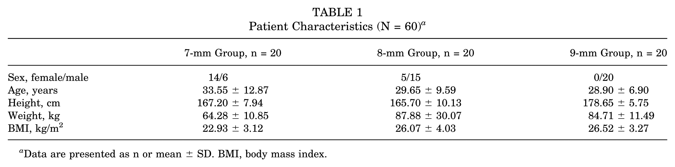
Data are presented as n or mean ± SD. BMI, body mass index.
Relationship Between the ACE and the Safe Line
The safe line of the 3 groups was located at the lateral femoral condyle medial wall within the range of the cartilage edge (Figure 5). The x-coordinate of the highest point in the cartilage was significantly smaller than that of the intersection point between the safe line and the cartilage edge in each group (7-mm group: 57.27 ± 7.32 vs 88.27 ± 6.17; P= .000; 8-mm group: 56.37 ± 6.90 vs 81.10 ± 8.23; P = .000; 9-mm group: 56.05 ± 3.98 vs 70.99 ± 14.85; P = .000). These findings indicated that the ACE was beyond the safe zone. The safe zone increased as the ACL bone tunnel diameter decreased (Figure 5D and Figure 6). The safe zones of the 7-mm, 8-mm, and 9-mm groups were in area ABC, area AB, and area A, respectively (Figure 5D and Figure 6).

The relationship between the cartilage edge and the safe line. (A-C) Scatter diagrams of the cartilage edge and safe line of each patient in the 3 groups. (D) Nonlinear fitting of the cartilage edge and safe line in the 3 groups. ABT, anterior cruciate ligament bone tunnel; ACE, anterior cartilage edge; CE, cartilage edge. The green line OH (ABC) or the green dotted line OH (D) represents the ACE.

Illustration of the ACE method. The tip of the aimer is positioned at the ACE of the lateral femoral condyle medial wall with the knee at 90° of flexion. ABT, anterior cruciate ligament bone tunnel; ACE, anterior cartilage edge; CE, cartilage edge. The green line (OH) represents the ACE.
Relationship Between the Tunnels and the Bone Bridge in ACLR and LET
The detailed results of the 10 patients with ACLR and LET are summarized in Table 2. There was no tunnel conflict in all 10 patients (Figure 7). The bone bridge thickness ranged from 3.15 to 8.92 mm.
Relationship Between the ACLR Femoral Tunnel and the LET Tunnel Created Using the ACE Method in 10 Patients Who Underwent ACLR and LET a
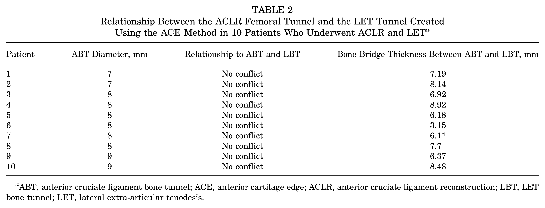
ABT, anterior cruciate ligament bone tunnel; ACE, anterior cartilage edge; ACLR, anterior cruciate ligament reconstruction; LBT, LET bone tunnel; LET, lateral extra-articular tenodesis.

The relationship between the ACL femoral tunnel and the (LET) tunnel drilled using the ACE method (no conflict). (A) Sagittal view of the lateral femoral condyle on postoperative 3D-CT. (B) Medial-frontal view of the lateral femoral condyle medial wall on postoperative 3D-CT. (C) Coronal view of the distal femur on postoperative CT. ABT, anterior cruciate ligament bone tunnel; ACE, anterior cartilage edge; ACL bone tunnel; ACL, anterior cruciate ligament bone tunnel; BBT, bone bridge thickness; CT, computed tomography; LBT, LET bone tunnel; LET, lateral extra-articular tenodesis; LET-et, LET bone tunnel exit point; LET-in, LET bone tunnel insertion point; 3D-CT, 3-dimensional computed tomography.
Discussion
In the present study, the use of 3D-CT analysis and application in actual surgery yielded 2 important findings. One finding was that the ACE was a stable landmark that could be used to guide the drilling of the LET bone tunnel to avoid tunnel convergence during ACLR and LET. The other finding was that using the ACE as a landmark and using an ACL aimer achieves a safe thickness of the bone bridge between the ACL femoral tunnel and the LET bone tunnel.
Compared with specific angles and orientations reported for use in ACLR by previous studies, the ACE is an accurate bony landmark that can guide the drilling in the precise desired direction. Jette et al 10 recommended that the ACL femoral tunnel should be drilled at an angle of 30° anterior in the axial plane and 30° proximal in the coronal plane. Suh et al 26 reported that convergence is safely avoided by using a distal angle of >24.3° and an anterior angle of >25.5° for the ACL tunnel. Zhu et al 28 suggested that the orientation of the ACL tunnel should be directed at least 30° anteriorly in the axial plane to minimize the risk of tunnel conflict. However, it is not always easy to guide the drill in these recommended directions, as the LET tunnel is usually created via freehand drilling. Furthermore, in these studies, the desired angle of the ACL tunnel was relative to the intercondylar notch or the transepicondylar axis of the femur.10,19,26 However, both of these reference structures are unreliable landmarks in the operative setting. The prevalence of intercondylar notch deformity is relatively high, causing the notch to have different shapes. 1 Although the transepicondylar axis of the femur is a relatively consistent landmark, it is difficult to identify accurate drilling orientations, especially in patients with obesity, in whom this anatomic landmark is difficult to palpate. Compared with the abovementioned methods, our method was based on the ACE, which can readily be identified in all cases under arthroscopy and is not influenced by deformity of the intercondylar notch and transepicondylar axis.
As there are important blood vessels and nerves distributed in the medial and posterior directions of the knee, it is particularly important to avoid vascular and nerve injuries while drilling bone tunnels. Some previous studies have suggested that the drilling directions should be aimed toward the anterior and proximal directions.10,19,28 However, when using the previous method, the exit point of the drill hole is located near the adductor canal, increasing the risk of injury to the femoral vessels and saphenous nerve. Furthermore, if the drilling direction is slightly posterior, it may damage the posterior cortical bone of the femoral shaft or cause the K-wire or the drill bit to penetrate the posterior part of the femoral shaft, increasing the risk of injury to the popliteal vessels, tibial nerve, and common peroneal nerve. If the drilling direction is slightly anterior, it may damage the trochlear cartilage. If the drilling direction is slightly distal, it may damage the intercondylar notch roof, thereby compromising the femoral attachment of the posterior cruciate ligament. Using the ACE as a landmark, combined with the ACL aimer for guidance, ensured that the bone tunnel was completely located within the lateral femoral condyle medial wall, avoiding the risk of nerve, vascular, cartilage, and ligament injury due to an uncertain exit position.
Another advantage of the ACE method is the ease of the operation. The position and direction of the LET bone tunnel suggested by previous studies are relatively fixed, making it difficult to determine the exact safe angle through multiplane combined assessment during surgery. 17 In contrast, the safe zone proposed in the present study can be measured and located using preoperative CT, and the intraoperative safe zone was visible, which effectively increased the safe space during the operation and reduced the difficulty for the surgeon. Some authors have described a single femoral tunnel technique using a single graft for reconstructing the ACL and the LET and eliminating the risk of tunnel collision. 27 However, this technique has its limitations regarding the required graft length and may not be suitable for some revision cases.
The safe minimum thickness of the bone bridge between the ACL femoral tunnel and the LET bone tunnel remains unclarified, and it is unclear whether tunnel convergence leads to long-term consequences such as graft failure.9,15 Nevertheless, it is intuitive that convergence between 2 tunnels may lead to problems such as poor graft integration, bone fracture, and even damage to the suspension device used for ACL fixation. Therefore, the present findings have important clinical relevance. The proposed safe line and safe zone allow surgeons to position the bone tunnel within the safe zone during surgery according to the actual situation, thus preventing tunnel convergence. Even if the LET tunnel exit point is close to the safe line, the thickness of the bone bridge is still greater than 2 mm. Furthermore, the LET exit point should be drilled close to the ACE to gain the maximum thickness of the bone bridge.
In the present study, the tunnel insertion point for the modified Lemaire LET was 10 mm proximal and 5 mm posterior to the lateral epicondyle in accordance with the original description of the technique by Lemaire. 14 Kittl et al 12 reported that a graft passed deep to the fibular collateral ligament and fixed to an area proximal to the lateral femoral epicondyle would have less strain and exhibit better isometry during knee motion. Indeed, one of the points tested by Kittl et al was the Lemaire point. The Lemaire point has also been confirmed to be the most effective in reducing residual knee anterolateral rotational instability as an insertion point for a complex anterolateral procedure. 11 An anatomic study reported that the Lemaire point coincides with the femoral origin of the anterolateral ligament. 6 LET fixation is most commonly achieved using a suture anchor and interference screw. However, even when using a suture anchor for fixation, which reduces the length and diameter of the bone tunnel and lowers the risk of tunnel convergence, the small contact area between the graft and the bone makes it difficult to achieve firm tendon-bone healing and may lead to graft failure. Therefore, using the ACE method to establish the LET bone tunnel position allows for the adjustment of graft tension under direct vision through interference screw fixation. Perelli et al 19 drilled the LET bone tunnel starting 5 to 10 mm proximal to the lateral epicondyle in line with the epicondyle and fixed the graft with an interference screw. However, the bone tunnel established by this method, with the exit point located on the medial side of the femur, may cause the graft tension suture to remain in the body for too long. In contrast, the bone tunnel established using the ACE method has its exit point located within the joint, allowing for the tension suture to be cut under direct vision and avoiding the risk of foreign body reaction caused by residual tension string.
The present study has 2 advantages over previous studies. First, the diameter of the ACL tunnel is an important factor in determining the risk of tunnel convergence. The larger the tunnel diameter, the greater the risk of convergence between the 2 tunnels. To our knowledge, no study has analyzed the ACL tunnel size and proposed methods with which to avoid tunnel convergence. We compared the commonly used 7-mm, 8-mm, and 9-mm ACL tunnel diameters and found that as the ACL tunnel diameter increased, the safe zone for the LET tunnel on the medial wall of the lateral femoral condyle decreased. This finding also reminds surgeons that when dealing with patients undergoing ACLR with larger tunnels, the insertion point of the LET tunnel should be positioned closer to the ACE. Second, because of variations in femoral morphology among patients, we introduced a coordinate system to standardize the safe lines and cartilage margins for each patient, using curve fitting to determine the positional relationship between the 2 tunnels.
This study has some limitations. As we did not investigate other surgical techniques, the findings may not apply to patients who are not undergoing ACLR using the transportal technique or to patients undergoing LET using the modified Lemaire technique. The present study focused on investigating the tunnel convergence. Therefore, the clinical outcomes of patients’ subjective evaluations and graft performance were not investigated. Furthermore, the retrospective and nonrandomized design of this study was a weakness. Thus, we will perform 3D-printed models for biomechanical testing validation in the future. Finally, we did not calculate the area of the LET safe zone for different ACL tunnel diameters. However, the coordinate graph shows that as the diameter of the ACL tunnel increased, the area of the LET safe area also increased, and that the ACE was located within the safe area. Therefore, it was considered unnecessary to calculate the specific area of the safe zone.
Conclusion
The ACE of the lateral femoral condyle medial wall is a useful landmark to drill the LET bone tunnel to avoid tunnel convergence in ACLR combined with LET.
Footnotes
Acknowledgements
The authors thank Dr Huizi Song and Dr Pudding for providing the imaging techniques and participating in the model processing.
Final revision submitted February 19, 2025; accepted March 28, 2025.
One or more of the authors has declared the following potential conflict of interest or source of funding: This work was supported by the Young Scientists Fund of the National Natural Science Foundation of China (No. 82402996), Peking University Medicine Sailing Program for Young Scholars’ Scientific & Technological Innovation (No. BMU2023YFJHPY023), Peking University Third Hospital Clinical Cohort Construction Project (Category C) (No. BYSYDL2023018), and Haidian District Health and Health Development Research Cultivation Program Project (No. HP2024-22-501003). AOSSM checks author disclosures against the Open Payments Database (OPD). AOSSM has not conducted an independent investigation on the OPD and disclaims any liability or responsibility relating thereto.
Ethical approval for this study was obtained from the Peking University Third Hospital Medical Science Research Ethics Committee (146-02).