
Abstract
Background:
Medial patellofemoral ligament (MPFL) reconstruction is a common treatment for patellar instability. Yet nearly 40% of revisions result from femoral tunnel misplacement. One reason may be the positioning of the C-arm relative to the knee.
Purpose:
To assess how the C-arm’s position affects femoral MPFL placement when the image receptor is positioned either contralateral or ipsilateral to the operated knee.
Study Design:
Controlled laboratory study.
Methods:
Ten human cadaveric knee specimens were dissected, and the femoral MPFL insertion site was identified and marked using a 10-mm eyelet. According to the possible clinical scenarios, true lateral radiographs in 2 different C-arm positions were taken. In the first scenario, the image receptor was on the ipsilateral side, being 5 cm away from the knee with the x-ray beam directed from medial to lateral (ML5). In the second scenario, the image receptor was on the contralateral side, being 25 cm away from the knee with the x-ray beam directed from lateral to medial (LM25). In each radiograph, the eyelet position was recorded and the distance (proximal-distal and anterior-posterior) from the optimal radiographic insertion point according to the literature was determined. Differences between the groups were calculated using the Wilcoxon signed-rank test, and a P value of <.05 was considered significant.
Results:
The anatomic femoral MPFL insertion in the ML5-position was located a mean of 2.7 ± 2.4 mm proximal and 4.5 ± 5.5 mm anterior to the Schöttle point. This resulted in an absolute distance of 7.2 ± 3.0 mm. In the LM25-position, it was located a mean of –0.7 ± 1.8 mm distal and 3.0 ± 5.3 mm anterior, which resulted in an absolute distance of 5.4 ± 3.2 mm. The ML5 was located more anterior (1.5 ± 2.1 mm) and proximal (3.4 ± 2.4 mm) compared with the LM25 position. Measurements following methods described in the literature significantly differed in both axes in the LM25 view when compared with the ML5 view measurements (P = .005).
Conclusion:
Compared with the ipsilateral C-arm position (ML5), the contralateral C-arm position (LM25) showed a smaller range with a lower standard deviation in identifying the femoral MPFL approach across all measurement methods.
Clinical Relevance:
When applying the method according to Schöttle et al to locate the femoral MPFL insertion point, it should be noted that in the proximal-distal orientation, the femoral MPFL insertion point is situated proximal to the Blumensaat line in the contralateral view (LM25). In contrast, when using the ipsilateral view (ML5), the femoral MPFL footprint is positioned just distal to the proximal edge of the medial condyle.
Keywords
Medial patellofemoral ligament (MPFL) reconstruction is an established procedure in the treatment of patellar instability.13,14 In isolation, or complemented by other procedures, it provides a passive restraint against lateral patellar dislocation in early knee flexion, 10 resulting in good to excellent clinical outcomes with low redislocation rates. 25 However, depending on the fixation technique and angle, complication rates of up to 26% ± 11% are reported. 28 To avoid such complications, anatomic femoral MPFL placement, especially in the proximal-distal direction, is crucial as suggested by several biomechanical studies.19,29,30 This is because misplacement of the femoral tunnel may lead to abnormal patellar tracking and therefore increase patellofemoral contact pressure.29,30
Intraoperative fluoroscopy with a true lateral alignment of the femoral condyles3,4,8,9,16-18,20,27 may prevent this femoral tunnel malplacement. However, 31% to 67% of femoral tunnels continue to be reported as nonanatomic in the literature6,22,27; furthermore, a recent meta-analysis showed femoral MPFL tunnel misplacement to be the primary cause in almost 40% of revision cases. 32 Schöttle et al 26 introduced a reproducible method in 2007 utilizing a true lateral view, which is now widely adopted. Subsequently, Balcarek and Walde 3 emphasized the importance of accurate superimposition of both femoral condyles, as a 5° divergence may lead to a critical misinterpretation and an approximate 5-mm shift from the native femoral insertion point. Stephen et al 30 correlated the anatomy of the MPFL with superimposed condyles in radiographs and proposed a 40-50-60 formula based on ratios. Conversely, Fujino et al 15 identified the femoral footprint in 3-dimensional computed tomography and then compressed this into a 2-dimensional projection with superimposed condyles. Another explanation as to why femoral tunnel malplacement could occur may be the position of the C-arm relative to the knee. A recent study demonstrated that there is a relevant difference between the ipsilateral and contralateral positions of the image receptor relative to the knee that is operated on when visualizing the same point. 21
This is likely due to the size distortion that is caused by the object-to-image-receptor distance (OID) when using fluoroscopy of 3-dimensional objects. The part of the object that is farther away from the image receptor is radiographically represented with greater size distortion than the parts of the object that are closer to the image receptor. 1 Therefore, the OID is a crucial factor in minimizing the size distortion on radiographic images. 1 For the specific task of localizing the femoral footprint of the MPFL, ≥2 distinct anatomic landmarks have to be visualized: the dorsal femoral cortex and the superposition of both the posterior and the distal margin of the femoral condyles. Intraoperatively, the position of the C-arm in relation to the knee that is operated on will therefore have a direct influence on the projection of the femoral MPFL insertion. This might explain the preference for certain C-arm positions, either ipsilateral or contralateral, during procedures (Figure 1).

True lateral view of medial patellofemoral ligament (MPFL) footprint with ipsilateral and contralateral positions of fluoroscopy using a large C-arm. The purple line shows the x-ray beam representing the femoral MPFL. The green line represents the x-ray beam of the posterior cortex of the femoral diaphysis. The blue line represents the x-ray beam of the wall of both femoral condyles. The contralateral knee is shown as a dashed grey femur. The femoral MPFL is displayed as a red point. The distance between source (S) and image receptor is 970 mm, corresponding to a large C-arm. The distance between the femoral diaphysis and medial patellofemoral ligament on the image receptor is for ipsilateral 24.3 mm and for contralateral 16.2 mm (a). The distance between the femoral diaphysis and both posterior borders of the femoral condyles on the image receptor is for ipsilateral 24.3 mm and for contralateral 36.4 mm (b).
Therefore, the goal of the present study was to determine the differences in femoral MPFL tunnel placement depending on the location of the C-arm. It was hypothesized that (1) the C-arm position would influence the tunnel placement in MPFL reconstruction and (2) the contralateral C-arm position is preferable due to the reduced OID effect.
Methods
Specimen Preparation
Following approval from our research ethics committee, 10 fresh-frozen cadaveric knees (2 left and 8 right) were obtained from MedCure. Five were female and 5 male with a mean age of 77 years (range, 67-95 years) and included 20 cm each of the femur and tibia. The specimens were preserved in polyethylene bags, stored frozen at –20°C, and thawed at room temperature for 24 hours before use. Ten cadaveric knees were sufficient according to our power analysis. The specimens were reused from a previous biomechanical study that always left the MPFL intact. Only knees with an intact MPFL and no history of patellofemoral dislocation, trauma, or surgery were used.
The skin and subcutaneous fat were removed, taking care to avoid damaging the medial retinaculum. The vastus medialis obliquus was elevated revealing the conjoined attachment of the vastus medialis obliquus tendon and the MPFL to the patella, allowing dissection of the MPFL to its femoral attachment. The medial femoral epicondyle and adductor tubercle were identified. The MPFL was tensioned anteriorly using a tweezer. The groove between these landmarks defined the center of the femoral attachment of the MPFL and was marked using a 10-mm eyelet (Figure 2). The point was consistently confirmed during dissection for all knees as the anatomic MPFL femoral origin.
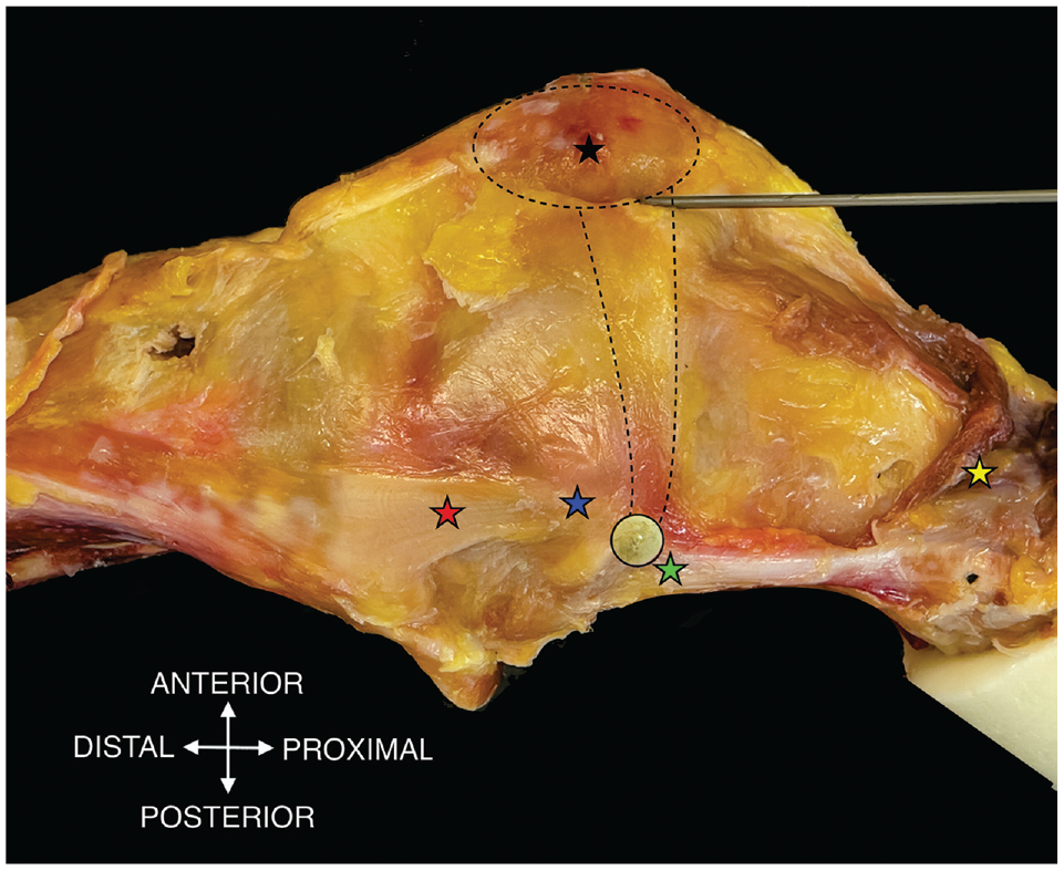
The medial side of a right knee is shown including key anatomical landmarks: adductor tubercle (green star), medial femoral epicondyle (blue star), superficial medial collateral ligament (red star), reflected vastus medial obliquus (yellow star), patella (black star), eyelet marking femoral medial patellofemoral ligament (MPFL) attachment (black circle), patella and MPFL (dotted lines).
Radiographic Assessment
To produce a true lateral radiograph, the knee was positioned onto a wooden box. Radiographic assessment of the femoral attachment point was achieved using a true lateral radiograph that superimposed both the posterior and the distal margins of the femoral condyles. 3 Images were acquired in the Digital Imaging and Communications in Medicine (DICOM) format using a C-arm (FPD 8 × 8–inch; Ziehm Imaging GmbH).
Two different fluoroscopic positions, simulating an intraoperative setting, were analyzed. The first setup positioned the base of the C-arm ipsilateral to the operated knee. The image receptor was positioned lateral to the knee at 5 cm (from image receptor to lateral femoral epicondyle) and the x-ray trajectory was from medial to lateral, which corresponded to the medial to lateral 5-cm position (ML5) (Figure 3).

C-arm is positioned on the ipsilateral side with the image receptor lateral to the femur corresponding to the medial to lateral 5-cm position. The tested knee (grey femur) was aligned onto a wooden box (black and grey square) and the contralateral knee was visualized (dashed grey femur).
For the second scenario, the C-arm base was placed on the contralateral side. For this, the image receptor was positioned medial to the knee at 25 cm (simulating the other leg as between image receptor and medial femoral epicondyle), and the x-ray trajectory was from lateral to medial, corresponding to the lateral to medial 25-cm position (LM25) (Figure 4).

C-arm is positioned on the contralateral side with the image receptor medial to the femur corresponding to the lateral to medial 25-cm position. The tested knee (grey femur) was aligned onto a wooden box (black and grey square) and the contralateral knee was visualized (dashed grey femur).
Measurement of MPFL Attachment Position
All measurements were made using a DICOM system (Version 3.3.6; Horos) and were calibrated to the 10-mm eyelet of the respective image.
The Schöttle point was identified according to the authors’ description. 26 Therefore, a line was drawn from the femoral posterior cortical outline. Perpendicular to this line, 2 lines were drawn at the proximal end of the Blumensaat line and the proximal edge of the medial condyle. The Schöttle point was identified at 1.3 mm anterior (y-axis) to the femoral posterior edge and 2.5 mm distal (x-axis) to the proximal outline of the medial condyle (Figures 5 and 6). The absolute distance between the Schöttle point and the midpoint of the 10-mm eyelet (anatomic femoral MPFL insertion), and the distance on the x-axis (proximal-distal) and y-axis (anterior-posterior) was measured. Additionally, the distance between the proximal end of the Blumensaat line and the anatomical femoral MPFL insertion was measured on the x-axis (proximal-distal).

A true lateral radiograph of the knee, taken with the limb in a medial to lateral 5-cm position, displays several key anatomical landmarks and reference points. A 10-mm eyelet is represented by a white circle. The center of the anatomical medial patellofemoral ligament (MPFL) attachement is indicated by a red arrow. Green lines on the radiograph depict the reference lines according to Schöttle et al., while a yellow dot marks the Schöttle point. White arrows illustrate the orientation of the x-axis and y-axis. In this specific example, the anatomic MPFL insertion is located 5.0 mm proximal along the x-axis and 0.3 mm posterior along the y-axis relative to the Schöttle point. The absolute distance between the anatomic MPFL insertion and the Schöttle point is measured at 5.0 mm.

A true lateral radiograph of the knee, taken with the limb in a lateral to medial 25-cm position, displays several key anatomical landmarks and reference points. A 10-mm eyelet is represented by a large gray circle. The center of the anatomical medial patellofemoral ligament (MPFL) attachement is indicated by a red arrow. Green lines on the radiograph depict the reference lines according to Schöttle et al, while a yellow dot marks the Schöttle point. White arrows illustrate the orientation of the x-axis and y-axis. In this specific example, the anatomic MPFL insertion is located mm distal along the x-axis and 6.7 mm anterior along the y-axis relative to the Schöttle point. The absolute distance between the anatomic MPFL insertion and the Schöttle point is measured at 7.5 mm.
Two other measurement methods that are often cited in the literature, those described by Stephen et al 30 and Fujino et al, 15 were used to assess the coordinates of the MPFL (Figure 7). For this, the MPFL attachment was described in relation to the corresponding 100% of their measurement's method in the x-axis and y-axis. Differences between the femoral MPFL insertion and the mean according to methods by Stephen et al 30 (x-axis = 50%; y-axis = 40%) and Fujino et al 15 (x-axis = 61%; y-axis = 42%) were calculated.

(A) According to Stephen et al, 30 the medial patellofemoral ligament (MPFL) attachment (red point) was defined in relation to the height of the medial femoral condyle (green double arrow; distance between turquoise and purple lines [100%]). (B) According to Fujino et al, 15 the MPFL attachment was defined in relation to the distance between the extension of the anterior femoral cortex and the posterior wall of the medial femoral condyle (green double arrow; distance between blue and turquoise lines [100%]). Coordinates on the x-axis (proximal-distal: black arrow) and the y-axis (anterior-posterior: yellow arrow) were reported as percentages in relation to the corresponding 100% of Stephen et al 30 and Fujino et al.
Statistical Analysis
A power analysis was performed for sample size estimation, using G*Power 3.1 12 (University of Düsseldorf) based on data from the study of Schöttle et al 26 (N = 8). The effect size in this study was 1.51 and is considered to be large using Cohen criteria. 7 With an alpha of .05, the calculated sample size needed to obtain a power of 80% was 9. Data are shown as mean ± SD with range. The Wilcoxon signed-rank test was utilized to ascertain the variance in positions among each measurement method, as well as to compare the individual measurement methods. P < .05 was established for determining statistical significance. All analyses were performed with IBM SPSS (Version 26.0).
Results
Macroscopically, the femoral insertion of the MPFL was always located in the groove between the adductor tubercle and the medial femoral epicondyle.
Method by Schöttle et al 26
The anatomic femoral insertion compared with the Schöttle point in the ML5 position was located a mean of 2.7 ± 2.4 mm (range, 0.2 to 5.8 mm) proximally and 4.5 ± 5.5 mm (range, –6.2 to 13.6 mm) anteriorly (Table 1). This resulted in an absolute distance of 7.2 ± 3.0 mm (range, 3.6 to 13.6 mm). In the LM25 position, it was located a mean of –0.7 ± 1.8 mm (range, –3.2 to 2.6 mm) distally and 3.0 ± 5.3 mm (range, –8.4 to 9.8 mm) anteriorly, which resulted in an absolute distance of 5.4 ± 3.2 mm (range, 1.1 to 9.8 mm). Wilcoxon signed-rank test showed a significant difference between the 2 C-arm setups in the x-axis (proximal-distal; P = .005). No significant difference could be determined when comparing the distance in the y-axis (anterior-posterior; P = .09) or the absolute distance between the ML5 and LM25 Schöttle points and the anatomic attachment of the MPFL (eyelets in the ML5 and LM25 radiograph; P = .11) (Table 1).
Measurements to the Anatomic Center of the Femoral MPFL Insertion (N = 10) a

Data are presented as mean ± SD (range). F-A distance, distance between Fujino point and anatomic point; LM25, 25 cm from lateral to medial; ML5, 5 cm from medial to lateral; MPFL, medial patellofemoral ligament; S-A distance, distance between Schöttle point and anatomic point; St-A distance, distance between Stephen point and anatomic point.
Significant at P < .05.
When looking at the distance between the center of the eyelet in the different setups, the ML5 center was located 3.4 ± 2.4 mm (range, 0 to 7.3 mm) proximal and 1.5 ± 2.1 mm (range, –2.7 to 4.9 mm) anterior to the LM25 center, which resulted in an absolute distance of 4.5 ± 2.1 mm (range, 2.4 to 8.8 mm) (Table 2).
Measurements to the Anatomic Center of the MPFL Insertion (N = 10) a

Data are presented as mean ± SD (range). LM25, 25 cm from lateral to medial; ML5, 5 cm from medial to lateral; MPFL, medial patellofemoral ligament.
Significant at P < .05.
The femoral MPFL insertion was 4.9 ± 1.6 mm (range, 2.7 to 7.2 mm) proximal to the Blumensaat line in the ML5 and 2.5 ± 2.2 mm (range, 0 to 6.4 mm) in the LM25. Wilcoxon signed-rank test was significant (P = .005) (Table 2, Figure 8).

Scatterplot showing the projected anatomic medial patellofemoral ligament footprint in ML5 and LM25 views in relation to the femoral posterior cortex and Blumensaat line. The anatomic MPFL in ML5 is indicated by red dots and the anatomic MPFL in LM25 is indicated by blue dots. MPFL, medial patellofemoral ligament; ML5, 5 cm from medial to lateral; LM25, 25 cm from lateral to medial.
Methods by Stephen et al 30 and Fujino et al 15
According to the method of Stephen et al, 30 the ML5 presented a femoral attachment of the MPFL at 45.9% ± 7.2% (range, 33.7% to 56.5%) from the posterior border of the medial condyle to the anterior border of the medial trochlea and 60.2% ± 4.5% (range, 52.8% to 66.3%) from the distal border of the medial condyle (Table 3). This resulted in an anatomic MPFL insertion that was found to be 6.7 ± 3.1 mm (range, 1.8 to 11.4 mm) proximally and 3.8 ± 4.7 mm (range, –4.11 to 11.8 mm) anteriorly, with a total distance of 8.8 ± 3.4 mm (range, 1.8 to 13.4 mm) (Table 1).
Distal and Posterior Distance to the Corresponding Eyelet in Both C-Arm Setups a

Data are presented as mean ± SD (range). LM25, 25 cm from lateral to medial; ML5, 5 cm from medial to lateral.
Significant at P < .05.
The LM25 presented a femoral attachment of the MPFL at 37.8% ± 6.2% (range, 26.7% to 46.2%) from the posterior border of the medial condyle to the anterior border of the medial femoral trochlea and 52.2% ± 4.8% (range, 45.6% to 59.3%) from the distal border of the medial condyle (Table 3). This resulted in an anatomic MPFL insertion that was found to be 1.6 ± 3.5 mm (range, –3.5 to 6.3 mm) proximally and 1.8 ± 4.8 mm (range, –10.5 to 4.6 mm) anteriorly, with a total distance of 5.6 ± 2.6 mm (range, 1.2 to 11.0 mm) (Table 1). In contrast to the method of Schöttle et al, 26 this was statistically significant in both directions (proximal-distal direction, P = .005; anterior-posterior direction, P = .005) (Table 1).
According to the method of Fujino et al, 15 the ML5 presented a femoral attachment of the MPFL at 51.7% ± 7.6% (range, 38.5% to 63.7%) from the posterior border of the medial condyle to the origin of the medial femoral trochlea and 67.9% ± 4.1% (range, 62.0% to 74.3%) from the distal border of the medial condyle (Table 3). This resulted in an anatomic MPFL insertion that was found to be 4.1 ± 2.5 mm (range, 0.6 to 8.3 mm) proximally and 5.6 ± 4.5 mm (range, –2.0 to 13.8 mm) anteriorly, with a total distance of 7.8 ± 3.5 mm (range, 2.1 to 14.2 mm) (Table 1).
The LM25 presented a femoral attachment of the MPFL at 45.2% ± 7.1% (range, 32.9% to 56.6%) from the posterior border of the medial condyle to the origin of the medial femoral trochlea and 62.3% ± 3.5% (range, 56.3% to 66.6%) from the distal border of the medial condyle (Table 3). This resulted in an anatomic MPFL insertion that was found to be 0.9 ± 2.3 mm (range, –3.0 to 3.9 mm) proximally and 1.9 ± 4.3 mm (range, –5.7 to 8.8 mm) anteriorly, with a total distance of 4.4 ± 2.6 mm (range, 0.6 to 8.8 mm) (Table 1). Wilcoxon signed-rank test resulted in a significant difference for the anterior-posterior direction (P = .005) and for the proximal-distal direction (P = .005) (Table 1).
Discussion
The most important finding of the present study was that changing the position of the C-arm significantly changed the radiographic femoral tunnel positioning of the MPFL, as determined by 3 different methods. When comparing ML5 with LM25, the same anatomic femoral MPFL attachment had a mean absolute distance of 4.5 ± 2.1 mm. Thus, a possible tunnel placement would be located more distal and posterior to the anatomic MPFL insertion using the ML5 compared with the LM25. This may lead to abnormal patellofemoral kinematics and patellar tracking24,29,30 and ultimately to a poor outcome for the patient.
Schöttle et al 26 were the first to describe an intraoperative measurement method to locate the femoral MPFL insertion using fluoroscopy. The MPFL insertion site, based on 8 cadaveric knees, was 1.3 mm anterior to the posterior femoral cortex line and 2.5 mm distal to the perpendicular line intersecting the proximal aspect of the medial condyle. Comparing these results with the present study's data, they seem to match the LM25 setting in the x-axis (3.2 ± 1.8 mm distal to the perpendicular line intersecting the proximal aspect of the medial condyle), but in the y-axis both settings show a more anterior position (ML5, 5.8 ± 5.5 mm; LM25, 4.3 ± 5.3 mm). These differences are possibly related to the OID effect, due to the different positioning of the C-arm. Neither the C-arm positioning nor the side of the knee (left or right) was mentioned in the study by Schöttle et al.
Apart from the Schöttle et al's original work, other studies identified the anatomic femoral MPFL insertion using fluoroscopy and showed a range of 0.5 to 8.8 mm anterior to the femoral posterior cortex and 0.9 to 3.2 mm proximal to the proximal end of the Blumensaat line (Table 4).4,23,26,30,33,35 Depending on the C-arm position, the present study showed a position of 5.8 ± 5.5 or 4.3 ± 5.3 mm anterior to the femoral posterior cortex and 4.9 ± 1.6 or 2.5 ± 2.2 mm proximal to the proximal end of the Blumensaat 5 line. Comparing these results from the literature with those of the present study, only the LM25 position was within the previously reported range. The ML5 setup showed a more proximal and anterior position. When compared to the results from the literature, it was outside the reported range along the proximal-distal axis.
Overview of Located MPFL, Radiographic Modalities, and Position a

2D, 2-dimensional; 3D, 3-dimensional; CT, computed tomography; LM25, 25 cm from lateral to medial; ML5, 5 cm from medial to lateral; MPFL, medial patellofemoral ligament.
Using a ratio-based technique, Stephen et al 30 set the anterior-posterior medial condylar diameter as 100%, determining the MPFL's femoral attachment at 41% from the medial condyle's posterior, 51% distally, and 59% anteriorly. Fujino et al, 15 using a similar approach with 2-dimensional lateral images of 3-dimensional reconstructed computed tomography scan, recorded the MPFL's posterior and distal insertions at 42% and 61%, respectively. LM25 measurements yielded 37.8% (posterior) and 52.2% (distal) using the method presented by Stephen et al 30 and 45.2% and 62.3% using the method presented by Fujino et al. Conversely, ML5 recorded 45.9% (posterior) and 60.2% (distal) for Stephen et al 30 and 51.7% and 67.9% for Fujino et al. The data suggest that LM25 aligns more closely with the methodologies of Stephen et al 30 and Fujino et al compared with ML5, potentially due to OID 1 variations. This study, as detailed in Tables 1 and 4, underscores the precision of LM25 in localizing the femoral MPFL location relative to ML5.
Due to the variety of results in radiographic MPFL studies (Table 4), a recent systematic review questioned whether fluoroscopic identification of the anatomic MPFL center was possible. 2 A reason for this variety of results in radiographic MPFL studies may be the specimen’s individual size and MPFL anatomy but may also come from the positioning of the C-arm, which resulted in a mean absolute distance of >4 mm in the present study. Furthermore, none of the previous studies provided information on C-arm positioning. Due to the statistically significant OID effect in the present study, this should be uniformly reported in future studies when looking at radiographic anatomy.
It should be emphasized that a large C-arm was used in this study similar to the research conducted by Schöttle et al. 26 In contrast, Wijdicks et al 33 and Ziegler et al 35 utilized a mini C-arm in their investigations, resulting in different findings. Ziegler et al contended that the radiographic tunnel localization method proposed by Schöttle et al lacks precision on a true lateral radiograph, suggesting that deviations from true lateral exacerbate this inaccuracy and therefore render such radiographic techniques obsolete. Instead, they advocated for a comprehensive assessment of anatomy without endorsing radiological identification of the femoral MPFL. The results of studies by Ziegler et al and Wijdicks et al cannot be directly compared with studies utilizing a large C-arm due to the distinct influence of the imaging device, explaining the significant variance in results.
Due to literature inconsistencies, some have suggested determining the MPFL insertion site by palpating between the medial femoral epicondyle and adductor tubercle rather than using radiographic techniques.24,31,34,35 However, palpation demands a larger incision, which is challenging in obese patients and revisions. Studies have indicated that radiological methods yield more consistent results than anatomic identification.16,18,20 Regardless of the method, varying positions can alter length change patterns, emphasizing the importance of isometry verification before graft fixation.
A recent meta-analysis stated that in 38.2% of revision cases, femoral MPFL tunnel misplacement was the most common complication. 32 Various biomechanical studies have agreed that >5-mm proximal misplacement led to an increase in medial peak pressure in the patellofemoral joint and nonisometric tunnel placement increased graft stress during knee joint flexion.11,29,30 A small error in the femoral tunnel placement combined with a small error in tensioning can reportedly result in either loss of flexion (femoral position too proximal) or an extensor lag as a result of an overtight graft in full extension (femoral position too distal). In the present study, each measurement method showed different results depending on the C-arm position. The differences were small and only statistically significant in the proximal-distal direction (Schöttle et al 26 ; P = .005), with the ML5 being more proximal. Thus, this may not be clinically relevant as patient-specific anatomy and the quality of the lateral radiograph may have a greater influence. However, surgeons should be aware of the OID effect shown in this study, and we recommend a uniform C-arm setup. We noted that subtle changes in the orientation of the true lateral image appeared to have a greater effect in the ML5 view compared with the LM25 view. Additionally, we found that adjusting the true lateral view appeared to be more straightforward in the LM25 configuration. However, as this was a qualitative observation without quantitative analysis, further confirmation is required.
Limitations
Several limitations of the present study need to be acknowledged. First, this was an in vitro study of a limited number of geriatric specimens with no history of patellofemoral pathology, which limits the representation of the full spectrum of anatomic variability. Second, no actual MPFL reconstruction was performed; therefore, no data on graft strain could be extracted. Third, in contrast to the C-arm setup in the operating room with different size knees, the distances from the image receptor to the knee were always perfectly set up in our study.
Conclusion
Compared with the ipsilateral C-arm position (ML5), the contralateral C-arm position (LM25) showed a smaller range with a lower standard deviation in identifying the femoral MPFL approach across all measurement methods. When applying the method according to Schöttle et al 26 to locate the femoral MPFL insertion point, it should be noted that the insertion point should be situated just proximal to the Blumensaat line in the contralateral view (LM25) in the proximal-distal orientation. In contrast, when using the ipsilateral view (ML5), the femoral MPFL footprint should be positioned just distal to the proximal edge of the medial condyle.
Footnotes
Final revision submitted May 16, 2024; accepted June 13, 2024.
The authors declared that they have no conflicts of interest in the authorship and publication of this contribution. AOSSM checks author disclosures against the Open Payments Database (OPD). AOSSM has not conducted an independent investigation on the OPD and disclaims any liability or responsibility relating thereto.
Ethical approval for this study was obtained from Medical Association of Westphalia-Lippe (No. 2022-174-f-S).