
Abstract
Background:
The retear rate after rotator cuff repair remains unacceptably high. Various biological engineered scaffolds have been proposed to reduce the retear rate. We have developed a double rip-stop repair with medial row knot (DRSK) technique to enhance suture-tendon strength and a novel engineered tendon-fibrocartilage-bone composite (TFBC) for rotator cuff repair.
Hypothesis:
DRSK rotator cuff repair augmented with TFBC will have better biomechanical properties than that of DRSK repair with an acellular dermal graft (DG).
Study Design:
Controlled laboratory study.
Methods:
Fresh-frozen canine shoulders (n = 30) and knees (n = 10) were used. TFBCs were harvested from the patellar tendon–tibia complex and prepared for rotator cuff repair. The infraspinatus tendon was sharply detached from its bony attachment and randomly assigned to the (1) control group: DRSK repair alone, (2) TFBC group: DRSK repair with TFBC, and (3) DG group: DRSK repair with DG. All specimens were tested to failure, and videos were recorded. The footprint area, tendon thickness, load to create 3-mm gap formation, failure load, failure modes, and stiffness were recorded and compared. Data were recorded as mean ± SD.
Results:
The mean load to create a 3-mm gap in both the control group (206.8 ± 55.7 N) and TFBC group (208.9 ± 39.1 N) was significantly higher than that in the DG group (157.7 ± 52.3 N) (P < .05 for all). The failure load of the control group (275.7 ± 75.0 N) and TFBC group (275.2 ± 52.5 N) was significantly higher compared with the DG group (201.5 ± 49.7 N) (P < .05 for both comparisons). The stiffness of the control group (26.4 ± 4.7 N/mm) was significantly higher than of the TFBC group (20.4 ± 4.4 N/mm) and the DG group (21.1 ± 4.8 N/mm) (P < .05 for both comparisons).
Conclusion:
TFBC augmentation showed superior biomechanical performance to DG augmentation in rotator cuff tears repaired using the DRSK technique, while there was no difference between the TFBC and control groups.
Clinical Relevance:
TFBC may help to reduce retear or gap formation after rotator cuff repair using the DRSK technique.
Keywords
Rotator cuff tear is the most common cause of pain and dysfunction in shoulders, and the prevalence increases with age. 11,13,38,40 With the development of techniques, an arthroscopic approach has been widely used for rotator cuff repair instead of an open approach. Improved clinical outcomes have been achieved after rotator cuff repair with respect to pain release and improved outcomes on the University of California Los Angeles Shoulder Scale and American Shoulder and Elbow Surgeons Subjective Shoulder Scale. 18 –20,22,28,35 However, the retear rate in large/massive rotator cuff repair remains very high. 10,15,18 –20 This could be ascribed to various factors such as poor tendon quality, high tension between tendon and suture, inferior fixation strength, and the slow healing process of the bone-tendon interface (BTI). 1,7,21,25,34 To reduce the retear rate and promote BTI healing, various biological and engineered patches have been developed, such as human acellular dermal allografts, 1,33,36,37 small intestinal submucosa, 8,12,14,30 and biodegradable synthetic polymers. 31,41,42 However, these patches can do little to regenerate the native bone-tendon transition zone, which is crucial for the integrity of the rotator cuff. 6,27
Leung et al 23 reported that the BTI between homogeneous tissues (tendon-tendon and bone-bone healing) had better healing quality than the healing between heterogeneous tissues (bone-tendon healing). Recently, a novel engineered tendon-fibrocartilage-bone composite (TFBC) for rotator cuff repair has been developed 16,24 that preserves the natural fibrocartilage zone, replacing difficult BTI healing with similar tissue healing interfaces (tendon-tendon and bone-bone). An in vivo study confirmed that TFBC enhanced rotator cuff healing by preserving the fibrocartilage zone. 25 Moreover, in order to enhance the suture-tendon interface strength at the medial row, we have developed a novel double rip-stop repair with medial row knot (DRSK) technique using the suture-anchor system. This technique could be used to apply the TFBC for arthroscopic rotator cuff repair.
The aim of this study was to compare the biomechanical properties of TFBC augmentation with commercial acellular dermal graft (DG) augmentation in an animal model of rotator cuff repair using the DRSK technique. We hypothesized that rotator cuffs augmented with TFBC will have better biomechanical properties compared with DG augmentation.
Methods
Study Design
A total of 30 fresh shoulders and 10 fresh knees were obtained from 15 mixed-breed dogs (weight, 20 kg) that were euthanized for other studies approved by our Institutional Animal Care and Use Committee. The 30 shoulders were randomly assigned to 1 of 3 groups: (1) DRSK repair alone (control group; n = 10); (2) DRSK repair with TFBC augmentation (TFBC group; n = 10); and (3) DRSK repair with acellular DG augmentation (DG group; n = 10). Our previous studies 16,25 showed that a sample size of 10 was enough to reach 80% power with α = .05 for biomechanical testing. Mechanical testing was performed after repair.
TFBC Fabrication
TFBCs (n = 10) were prepared based on previously established procedures. 16,24,25 Briefly, patellar tendons were transected near the distal patellar bone. The tibial tubercles with the intact patellar tendon–tibial bony attachments were cut carefully with a bone saw (Figure 1A). The tibial bony attachment of all samples was trimmed to 5 mm in width (Figure 1B), after which the tendon was cut into 2 layers horizontally (Figure 1C). The TFBCs were immersed in liquid nitrogen for 2 minutes and then thawed in saline at 37°C for 10 minutes. This procedure was repeated 5 times for the devitalization of the tendons. The decellularization of TFBCs was performed by incubating the TFBCs in nuclease solution (RNase, 100 µg/mL; DNase, 150 IU/mL; Roche Diagnostic) at 37°C for 12 hours, followed by 3 rinses in phosphate-buffered saline (PBS). After storage at –80°C for 1 hour, the TFBCs were lyophilized in a freeze dryer (Millrock Technology) (Figure 1D). Before repair, the TFBCs were rehydrated in PBS for 24 hours.

Preparation of the TFBC. (A) The front view of the harvested patellar tendon with the tibial bony attachment. (B) The bony part was trimmed to 5 mm in width and (C) the tendon was cut into 2 layers horizontally. (D) The final TFBC scaffold after lyophilizing. TFBC, tendon-fibrocartilage-bone composite. (Images courtesy of Mayo Clinic.)
Rotator Cuff Repair
The infraspinatus muscle and infraspinatus tendon-humeral head were carefully dissected, and other soft tissues were removed from the humeral head. Rotator cuff tears were created as previously described. 16,25,36 The infraspinatus tendon was sharply transected at its insertion site. Footprint dimensions, tendon thickness at the distal and proximal end of insertion, as well as the thickness of tendon where the suture passed through were measured with a digital caliper (Johnson Level & Tool Mfg Co).
Two 4.5-mm medial suture anchors (BioComposite Corkscrew FT Anchor), loaded with No. 2 FiberWire (Arthrex) and two 3.5-mm lateral anchors (BioComposite Pushlock; Arthrex) were used for each repair. The prepared shoulders were randomly allocated to the 3 study groups: control group (repair alone; Figure 2), TFBC group (repair with TFBC; Figure 3), and DG group (repair with acellular DG; Figure 4). Authors Z.W. and Z.L. performed all surgery repairs together.

Schematic surgical procedure for the control group. (A) Two medial anchors were inserted at the articular margin, and the suture limbs of each anchor passed through the tendon. (B) One suture limb of each anchor was passed through the tendon to form a loop on the bursal side of the tendon. (C) After passing the limb laterally around the anchor, this limb was then shuttled back through the tendon to form the first rip-stop on the articular side, followed by (D) passing this suture limb through the loop on the tendon surface to form the second rip-stop. (E) One square knot was tied for each medial anchor. (F) One suture limb from each medial row anchor was secured to the greater tuberosity with 1 of 2 knotless anchors. (Images courtesy of Mayo Clinic.)

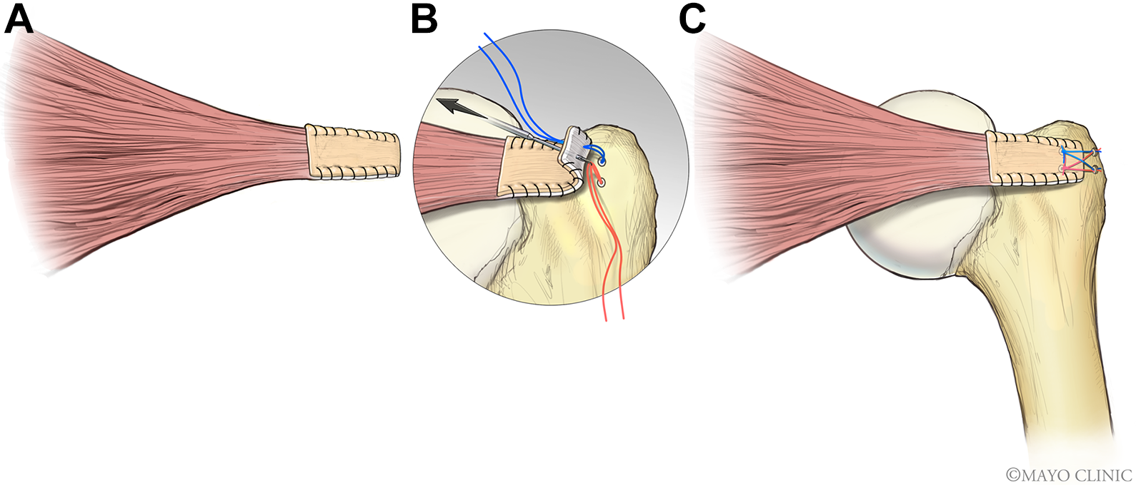
Schematic surgical configuration for the TFBC group. (A) 6-0 polydioxanone suture was utilized to close the edges of the sandwich-like constructs. (B) A bone trough was created to fit the bony segment of TFBC, followed by insertion of 2 medial anchors at the articular margin. The medial sutures of each anchor were passed through all the layers of the sandwich-like construct. The entrance of the sutures that were passed through the construct was 5 mm medially from the native tendon stump. (C) The final configuration of TFBC repair. TFBC, tendon-fibrocartilage-bone composite. (Images courtesy of Mayo Clinic.)
Schematic surgical configuration for the DG group. (A) The edges of the DG and tendon were closed using a running suture. (B) Two medial anchors were inserted at the articular margin. The medial sutures of each anchor passed through both the tendon and the graft, respectively. The entrance of the sutures passed through the tendon and graft was 5 mm medially from the native tendon stump. (C) The final configuration of the DG repair. DG, dermal graft. (Images courtesy of Mayo Clinic.)
Control Group
Two medial row anchors were placed along the articular margin. After passing 2 suture limbs of each anchor through the tendon (Figure 2A), 1 limb of each anchor was passed through the tendon from the bursal surface to the articular surface. Thus, a loop was formed on the bursal surface of the infraspinatus tendon (Figure 2B). This suture limb was passed laterally around the anchor and then back through the tendon from the articular surface to the bursal surface, thus forming a rip-stop at the articular surface (Figure 2C). Finally, this limb was passed through the loop on the bursal surface to develop the second rip-stop (Figure 2D). The suture limbs of the other anchor were made to perforate the tendon in the same way. Hence, 2 rip-stops were formed on the articular side (Figure 2C) as well as on the bursal side (Figure 2D). One square knot was tied for each medial anchor (Figure 2E). One suture limb from each medial row anchor was secured to the greater tuberosity with 1 of 2 knotless PushLock anchors. The lateral row anchors were inserted 10 mm apart, lateral from the medial anchors (Figure 2F). The sutures were pretensioned before lateral row fixation as per the manufacturer’s instructions.
TFBC Group
The detached infraspinatus tendon was sandwiched between the 2 tendon layers of TFBC, 16,25 and the edges of the sandwich-like constructs were closed using continuous 6-0 polydioxanone suture (PDS; Ethicon) (Figure 3A). Then, a bone trough was created to fit the bony segment of TFBC (Figure 3B). The medial sutures of each anchor were passed through all the layers of the sandwich-like construct (Figure 3B). The entrance of the sutures that were passed through the construct was 5 mm medial from the native tendon stump. The next steps were performed the same way as in the control group (Figure 2, B-E) until 1 square knot was tied for each medial anchor. One suture limb from each medial row anchor was secured to the greater tuberosity with 1 of 2 knotless PushLock anchors. When the lateral row was established, the bony part of the TFBC was fixed in the bone trough. The lateral row anchors were inserted 10 mm apart, lateral from the medial anchors (Figure 3C). In the final configuration, 5 mm of bony segment and 5 mm of native tendon filled the gap between the 2 rows of anchors.
DG Group
The DG (GraftJacket, Maxforce-Extreme; Wright Medical Technology) was prepared as per the manufacturer’s manual. Briefly, after immersion in saline at 37°C for 5 minutes, the backing was removed from the graft and then transferred to a second bath with saline. The graft was submerged completely and soaked until the tissue was fully rehydrated. Finally, the graft was cut to the same size as the TFBC. The lateral edge of the DG covered the native tendon stump 5 mm laterally, and then the edges of graft and tendon were sutured together using 6-0 PDS (Ethicon) (Figure 4A). Two medial anchors were placed at the articular margin (Figure 4B). The medial sutures of each anchor were passed through both the tendon and the graft layers (Figure 4B). The entrance of the sutures that were passed through the tendon and graft was 5 mm medial from the native tendon stump. The next steps (Figure 2, B-F) were the same as in the control group (Figure 4C). In the final configuation, 5 mm of DG and 5 mm of native tendon filled the gap between the 2 rows of anchors.
Mechanical Testing
The distal humerus of all the repaired samples was fixed into a plastic tube containing bone cement. A servohydraulic materials testing machine (MTS 312; MTS Systems Corp) was used for mechanical evaluation, and the infraspinatus muscle was gripped in a custom-designed cryoclamp, and the humeral shaft was mounted with an angle of 75º between the long axis of the humeral shaft and the infraspinatus tendon to mimic the anatomic position of the tendon. The infraspinatus tendon, the greater tuberosity, and the bony part of the TFBC/distal edge of the DG were marked with blue spots. 16 The rate used for failure testing was set at 30 mm/min. 16,25 Failure mode, displacement-force curve, and ultimate failure load were recorded on video and processed with ImageJ. Stiffness was then calculated from the slope of the linear region of the load-displacement curve.
Statistical Analysis
Numerical data are presented as mean ± SD, with 95% CI. Footprint dimensions, tendon thickness, and mechanical properties (ultimate failure load, stiffness, and load to create 3-mm gap formation) were compared using 1-way analysis of variance and the Tukey post hoc test. P < .05 was set as indicating statistical significance.
Results
Tendon Thickness and Footprint Dimensions
No grossly abnormal anatomy was observed in any sample. There were no significant differences among the 3 groups regarding tendon thickness, footprint dimensions, or footprint area (Table 1). The thickness of DG we used was 2 mm, 3,5 so the final thickness of the repaired construct was about 4 mm for both the TFBC and the DG groups.
Tendon Thickness and Footprint Dimensions a

a Data are shown as mean ± SD. DG, dermal graft; TFBC, tendon-fibrocartilage-bone composite.
b The tendon thickness where the suture passed through.
Load to Create 3-mm Gap Formation
The mean load to create a 3-mm gap between the lateral tendon edge and humeral head was 206.8 ± 55.7 N (95% CI, 172.5-241.1 N) for the control group, 208.9 ± 39.1 N (95% CI, 173.5-244.3 N) for the TFBC group, and 157.7 ± 52.3 N (95% CI, 122-193.4 N) for the DG group. The mean load for both the control and TFBC groups was significantly higher than that for the DG group (P = .038 and P = .033, respectively). There was no significant difference between the control and TFBC groups (Figure 5).

Comparison of load to create a 3-mm gap formation for 3 groups (mean ± SD). DG, dermal graft; TFBC, tendon-fibrocartilage-bone composite. *P < .05.
Failure Modes
No anchor pullout, suture breakage, or suture-anchor loosening was observed in any group. All samples in the 3 groups failed by suture cutting through the native infraspinatus tendon. For the TFBC group, the tendon slipped out from the 2 graft tendon layers; no TFBCs were cut through by the suture. After the failure test, the tendon part of the TFBC construct was still spanning over the infraspinatus tendon. For the DG group, the DGs remained intact after the failure test.
Maximum Load to Tensile Failure
The maximum failure load of the control group (275.7 ± 75.0 N; 95% CI, 222-329.3 N) was similar to that of the TFBC group (275.2 ± 52.5 N; 95% CI, 235.7-314.7 N). Both the control and the TFBC groups had a significantly higher failure load compared with the DG group (201.5 ± 49.7 N; 95% CI, 164-238.9 N) (P = .019 and P = .007, respectively). No significant difference was observed between the control and TFBC groups (Figure 6).

Comparison of maximum load for 3 groups (mean ± SD). DG, dermal graft; TFBC, tendon-fibrocartilage-bone composite. *P < .05, **P < .01.
Typical Displacement Versus Force Curve
Typical displacement-versus-force curves for the 3 groups are shown in Figure 7. The stiffness was calculated according to the linear part of the displacement-force curve. The 3 groups showed different patterns for the toe region of the curve (Figure 7).
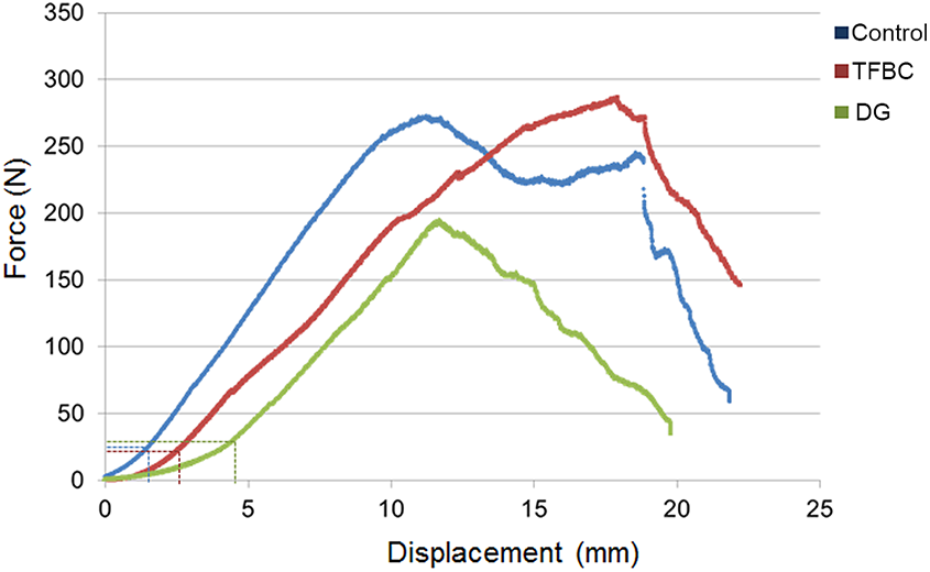
Typical displacement-force curves for the 3 groups. The dotted lines in blue, red, and green denote the toe region of the curve for the control, TFBC, and DG groups, respectively. DG, dermal graft; TFBC, tendon-fibrocartilage-bone composite.
Stiffness
The stiffness of the control group (26.4 ± 4.7 N/mm; 95% CI, 23.1-29.7 N/mm) was significantly higher than that of the TFBC group (20.4 ± 4.4 N/mm; 95% CI, 17.5-23.2 N/mm; P = .006) and DG group (21.1 ± 4.8 N/mm; 95% CI, 17.3-24.5 N/mm; P = .021). No statistically significant difference was seen between the TFBC and DG groups (Figure 8).

Comparison of stiffness for 3 groups (mean ± SD). DG, dermal graft; TFBC, tendon-fibrocartilage-bone composite. *P < .05, **P < .01.
Discussion
In this study, we compared the biomechanical properties of TFBC and DGs in a canine rotator cuff repair model using the DRSK technique. The results showed that TFBC augmentation had significantly better biomechanical properties compared with DG augmentation in terms of load to create a 3-mm gap formation and failure load. However, TFBC augmentation did not further improve the biomechanical properties compared with the control group. Moreover, the DG had inferior biomechanical properties compared with the control group with regard to load to create a 3-mm gap, failure load, and stiffness.
In recent decades, biologic scaffolds have been widely investigated to augment rotator cuff repair. In order to reduce immunogenicity of the allografts, many biologic scaffolds have been derived using the decellularization technique. However, these scaffolds were engineered with a single tissue (ie, tendon, cartilage, or bone). 9,25,38 In order to transform the difficult healing of 2 entirely different tissues (bone to tendon) to much easier homogeneous tissue healing (tendon-tendon and bone-bone), a book-shaped engineered TFBC was invented, 16 which has shown potential for rotator cuff repair. 9,26,32,39 In addition, TFBC includes the natural fibrocartilage zone, which is difficult to regenerate after rotator cuff injury.
Ji et al 16 demonstrated that the TFBC significantly enhanced the biomechanical properties of a rotator cuff repair in vitro, compared with traditional Mason-Allen repair, a surgical technique for open rotator cuff repair. An in vivo study conducted by Liu et al 25 also showed that rotator cuff repaired with TFBC improved the histology at the BTI compared with repair alone, although the mechanical properties between these 2 groups were no different at 6 weeks postoperatively. In the study by Liu et al, 25 TFBC was used as scaffold to carry stem cells for biological augmentation. In order to secure the transplanted cells in place, a running suture was used to close the edge. In order to maintain the consistency of the surgical repair technique in the current in vivo study, we added running suture in both augmentation groups. However, the results of the current study showed that the load to create a 3-mm gap formation and the failure load of the TFBC group was similar to that of the control group, unlike the findings of Ji et al. 16 This can be ascribed to the different rotator cuff repair suture configurations utilized in the current study. In the study of Ji et al, the infraspinatus tendons were repaired with modified Mason-Allen sutures through 2 bone tunnels for the control group, and for the TFBC group, modified Mason-Allen sutures were used to repair the patellar tendon to the greater tuberosity. Two parallel loops were sewn through the full thickness of the sandwich-like tendon interface with 3-0 polyglactin sutures, and the bone fragment of the TFBC was fixed to the attachment point of the infraspinatus tendon using a metal wire threaded through 2 bone tunnels introduced into the humeral head. This surgical procedure was different from the suture-anchor system of the current study, which is commonly used in arthroscopic surgery. In our study, the failure load of the repaired rotator cuff using the DRSK technique was very similar to that reported for the modified Mason-Allen repair described in Ji et al’s paper, but the DRSK technique could be used arthroscopically.
GraftJacket is acellular dermal matrix that is commercially available for rotator cuff repair augmentation. In 2006, Adams et al 1 reported that acellular dermal matrix was suitable for rotator cuff repair in a canine model. In vitro studies 4,29 have confirmed that augmentation with acellular dermal matrix enhances biomechanical performance compared with repair alone. On the contrary, our results showed that the use of acellular dermal matrix decreased the biomechanical properties compared with the control group in terms of load to create 3-mm gap formation, ultimate failure load, and stiffness. The reason that the DG group showed lower biomechanical properties than the control group was unclear. We speculate that the main reason may be related to the suture technique applied in the DG group, rather than to the graft itself.
In the current study, the infraspinatus tendon was covered with acellular dermal matrix on the bursal side, and the edges of the acellular dermal matrix and infraspinatus tendon were sewn using a running suture. Then, the DRSK technique was performed. Jung et al 17 investigated a similar construct, the “integrated” technique, and found inferior biomechanical properties of augmentation with acellular dermal matrix compared with repair alone, similar to our results. However, some studies 4,29 have shown increased strength with DG augmentation. Omae et al 29 reported that DG significantly increased failure strength but not stiffness. In the study by Omae et al, a single-row technique for repair alone (control) was compared with the double-row technique for DG augmentation. In contrast, we used the double-row technique across all our study groups in order to maintain consistency.
In our failure mode results, the native tendon slipped out from the 2 layers of TFBC. However, in the DG group, the failure mode was only cutting through the infraspinatus tendon while the DG remained intact. In a study by Barber et al, 5 a horizontal mattress stitch 5-mm wide was placed 5 mm from the edge of the graft. In their study, the mean load to failure of the suture graft construct for DG was 229 N, which was much higher than our results for the load to create 3-mm gap for the DG group (157.7 ± 52.3 N) and close to our results for failure load of the DG group (201.5 ± 49.7 N). The failure load of the DG in the Barber et al 3 study was 532 N. Hence, during the failure testing, the native tendon was first cut through by the suture while the DG remained intact. From our results, we did not find any benefit of TFBC augmentation in terms of mechanical performance when we used a strong repair technique with a double-row suture anchor system. However, TFBC has been reported as providing biological augmentation if it serves as an extracellular matrix scaffold combined with cell transplantation. 25 Future experimental studies are needed to better understand the role of TFBC augmentation.
The stiffness of both the TFBC and DG groups was significantly lower than that of the control group. But there was no significant difference between the TFBC and DG groups. There are 2 possible reasons for the lower stiffness of the TFBC and DG groups. The first explanation is that the TFBC or acellular dermal matrix was not entirely sutured to the native infraspinatus tendon; only the edges were closed using 6-0 PDS running suture. Thus, the final constructs of the TFBC and acellular DG were not activated simultaneously during the tensile failure test. The second explanation is that thicker constructs will cause less loop security (larger loops, greater suture length between anchors and knots, greater stretch, and therefore lower stiffness). With respect to gap formation, the longer toe region observed for the DG group may be caused in part by the material properties of skin and dermis, where collagen fibers are less highly aligned than in the tendon tissue of both the control and TFBC groups. The calculated stiffness for the 2 grafted constructs was similar. That is consistent with Figure 7: once beyond the toe region, all collagen fibers are recruited, and the slopes of the 2 constructs appeared similar to each other and to the native tendon. Therefore, the DG group could have greater initial gapping compared with TFBC, but the stiffness was similar in the 2 groups based on the slope beyond the toe regions. Theoretically, one might potentially reduce initial gapping by pretensioning the DG in order to load it beyond the toe region before fixation.
During the tensile failure test, all samples failed by the suture cutting through the tendon. One interesting item to note in the TFBC group was that the tendon part of the TFBC still covered the native tendon after the suture cut through the infraspinatus tendon. The same situation was also observed in the DG group. After rotator cuff repair, there is gap formation during inappropriate movement of the shoulder joint. It was helpful to bridge the gap between the tendon and humeral head during shoulder movement after repair, which would facilitate healing in vivo. But this would need to be confirmed in further studies.
The limitations of this study include the following aspects. First, a canine rotator cuff repair model was used. Although the anatomy of the rotator cuff in dogs is different from humans, the canine rotator cuff model has been widely used for more than 20 years, because the canine infraspinatus tendon is similar to the supraspinatus of humans. 1,2,16,25,36 Second, this was a time-zero biomechanical study, which cannot be directly translated to an in vivo biological healing process. However, the primary stability after repair plays a crucial role in reducing gap formation between the tendon and humeral head to facilitate healing, and so our findings are relevant to in vivo outcomes. Third, only 1 suture technique was used for the TFBC and DG groups. We did not compare our DTSK technique with the Mason-Allen or other techniques. Although the DRSK technique might not be optimal for acellular dermal matrix, there is still no consensus as how to augment rotator cuff repair with acellular dermal matrix. Furthermore, the purpose of this study was to compare the biomechanical properties of rotator cuff repair augmented with TFBC and acellular dermal matrix under the same conditions rather than the influence of different techniques. Finally, placing a running suture with 6-0 PDS suture would be quite challenging under arthroscopy, and the effect of the running suture on the biomechanical properties of repair was not clear.
The current study has some strengths. First, the utilization of young mature canine cadavers of similar age and weight eliminated many potential biases caused by bone quality, tendon degeneration, and difference in size. The size of the infraspinatus tendon and footprint area among the 3 groups was consistent, as shown in Table 1. Second, 2 orthopaedic surgeons performed all the repairs and 1 investigator completed the biomechanical tests, providing consistency to the methods.
Conclusion
This study demonstrated that TFBC augmentation showed superior biomechanical performance compared with acellular DG augmentation in rotator cuff tears repaired with the DRSK technique, while there was no difference between the TFBC and control groups.
Footnotes
Acknowledgment
The authors thank Ramona L. Reisdorf for harvesting the samples.
Final revision submitted February 26, 2020; accepted March 9, 2020.
One or more of the authors has declared the following potential conflict of interest or source of funding: This work was supported by a grant from the NIH/NIAMS (AR073811-01A1). Mechanical testing was supported by the Mayo Clinic Materials and Structural Testing Core Laboratory. Z.W. and Z.L. are funded by the China Scholarship Council. Z.W. was also supported by the Fundamental Research Funds from the Central Universities of Central South University (2017zzts214). S.L.M. has received educational support from Axogen; consulting fees from Ascension Orthopedics, Axogen, and Integra LifeSciences; speaking fees from Ascension Orthopedics; and royalties from Integra Lifesciences. S.P.S. has received consulting fees from Acumed, speaking fees from Arthrex, and royalties from Zimmer Biomet. AOSSM checks author disclosures against the Open Payments Database (OPD). AOSSM has not conducted an independent investigation on the OPD and disclaims any liability or responsibility relating thereto.
Ethical approval was not sought for the present study.